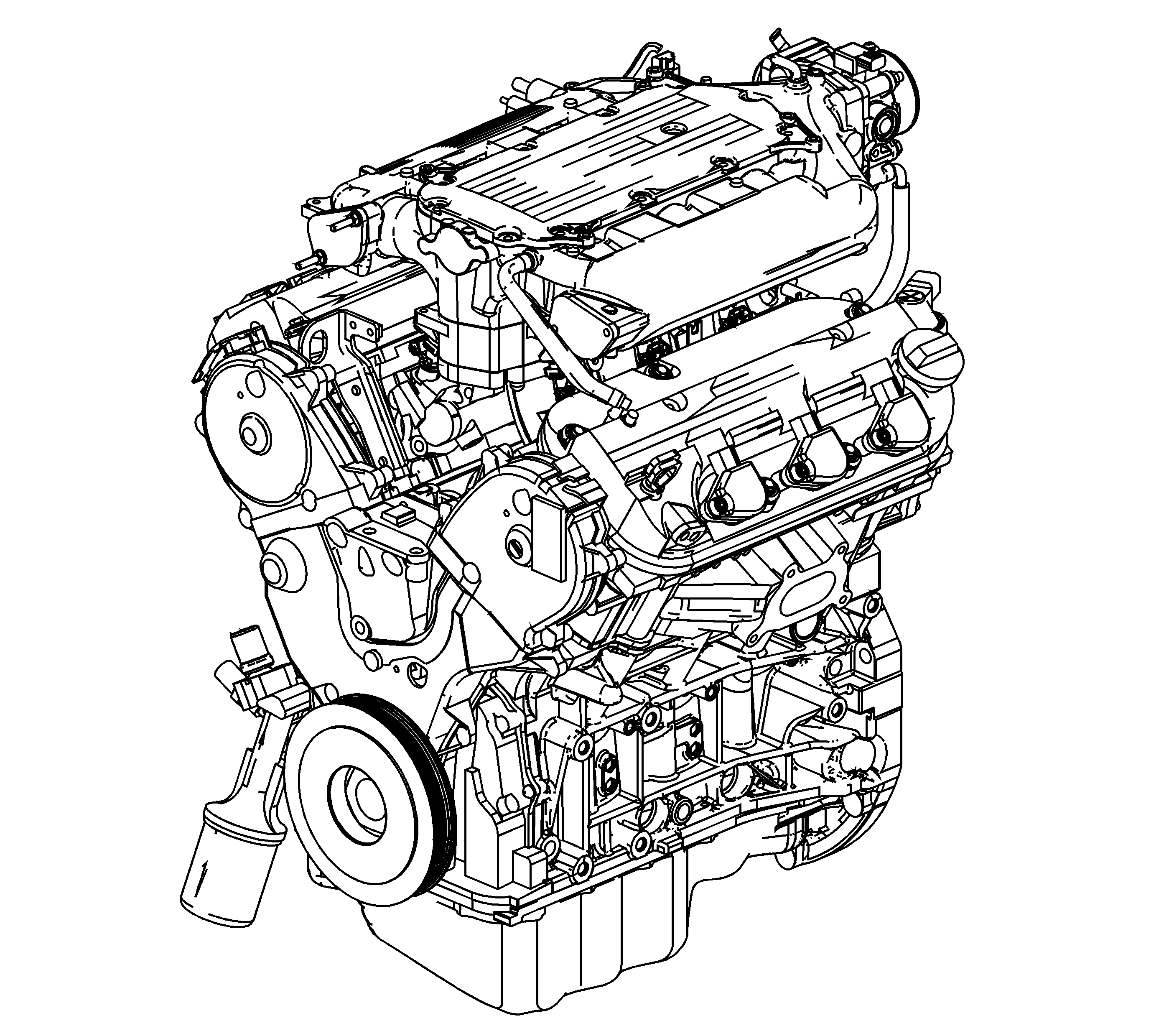
The 3.5L, 4-stroke, single overhead cam (SOHC) engine is identified as RPO L66 and VIN U. The V6 engine is a 24 valve variable valve timing and lift electronic control design.
Intake Manifold
The cast aluminum intake manifold incorporates passages for air intake to each cylinder and a passage for the exhaust gas recirculation (EGR) system. The drive-by-wire throttle body and the intake air temperature (IAT) sensor are mounted to the intake manifold. The positive crankcase ventilation (PCV) hose and evaporative emission (EVAP) valve are connected to vacuum fittings on the manifold.
Camshaft Drive System
The crankshaft drive sprocket rotates the timing belt and in-turn rotates the camshaft sprockets. Belt tension is provided by the hydraulic auto-tensioner assembly. The hydraulic auto-tensioner automatically compensates for tension variations caused by changes in belt temperature. A timing belt idler pulley and a timing belt tensioner pulley are also incorporated into the design. 2 steel camshafts, 1 per bank, are used to operate both intake and exhaust rocker arms. The timing belt also drives the water pump assembly.
Valve Train
1 intake and 1 exhaust rocker arm shaft are used for each cylinder bank. Rocker shafts are retained to the cylinder heads by bolts. 5 roller type rocker arms are used for each cylinder, 3 intake and 2 exhaust. The rocker arms pivot on the rocker shafts. Each rocker arm has a nut and bolt type mechanical adjuster. Periodic valve adjustment is required. Refer to Intake Rocker Arm Control System Operation .
Cylinder Head
The cast aluminum cylinder heads have 2 intake and 2 exhaust valves per cylinder. The cylinder head has line-bored camshaft journals. This design eliminates the use of bearing caps and retaining bolts and improves the ease of assembly. The single overhead camshaft is installed into the cylinder head from the rear or back-side of the head. The camshaft cap retains the camshaft and controls camshaft end-play. The valve rocker arm shafts are directly fastened onto the cylinder head with 1 dowel pin at each end of the shaft for positioning. The valve guides and valve seats are pressed into the head. The valve guides are replaceable, but must be reamed for proper guide-to-valve stem clearance after installation. The catalytic converters mount directly to the side of each cylinder head.
Piston and Connecting Rod Assemblies
The pistons are cast aluminum with a flat top design. Piston skirts are coated to reduce friction. Each piston uses 2 compression rings and 1 3-piece oil control ring assembly. The piston pin is a full-floating design and is retained to the connecting rod by clips located in each end of the piston pin bore. The connecting rod and rod cap are positioned and aligned by a dowel pin and retained by bolts.
Crankshaft
The crankshaft is of a cast iron design. The crankshaft is supported by 4 main bearings. The bearings are retained by bearing caps which are machined with the engine block for proper alignment and clearance. Journal number 3 is the thrust journal. Flat areas on the front of the crankshaft drive the oil pump assembly. A keyway and key on the front of the crankshaft align and position the timing belt drive sprocket and crankshaft balancer.
Engine Block
The cast aluminum V-shaped engine block is a deep-skirt design with 4 main bearing caps. The iron cylinder liners are a cast in place design. Coolant jackets encircle the cylinders. The 4 cast-iron bearing caps are cross-bolted to the engine block and each are retained by 2 vertically and 2 horizontally located bolts. Right side cylinders are numbered front-to-rear as 1-2-3. Left side cylinders are numbered front-to-rear 4-5-6. The firing order is 1-4-2-5-3-6.
Oil Pan
The cast aluminum oil pan retains the engine oil sump. The oil pan is positioned to the engine block by dowel pins and sealed to the engine block with an RTV type sealant.
Ignition
The V6 engine uses a coil-on-plug direct-ignition design. The camshaft position (CMP) sensor is mounted to the left-upper rear timing belt cover. The left camshaft sprocket has 3 spokes, or protrusions, incorporated into the rear of the sprocket that are used to create the camshaft sensor input signal. The dual-sensor crankshaft position (CKP) sensor assembly is located at the front of the engine at the oil pump housing. The timing belt drive sprocket has 22 spokes, or protrusions, incorporated into the rear edge of the sprocket that are used to create the crankshaft sensor input signal.
