For 1990-2009 cars only
Disassembly Procedure
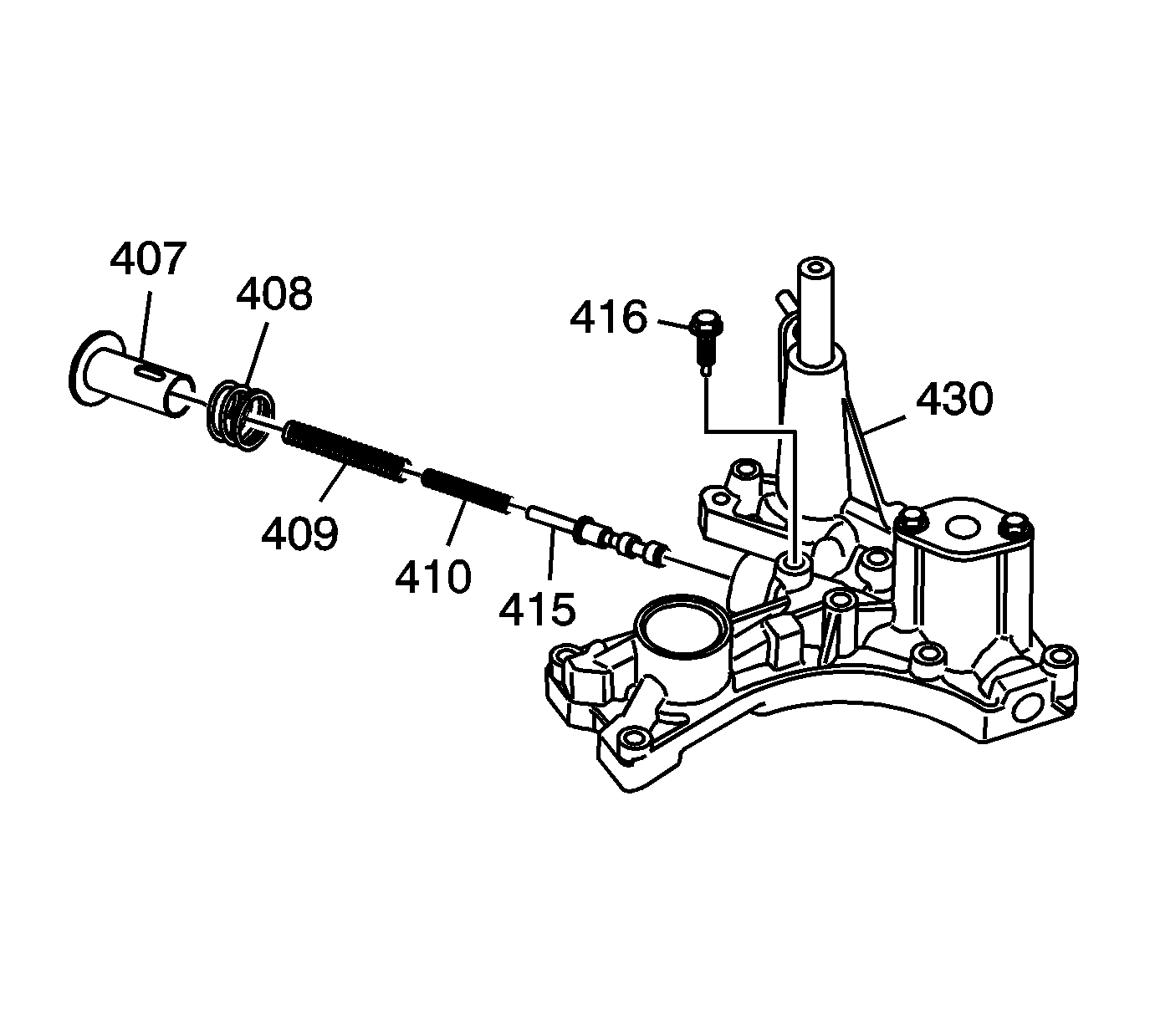
- Hold the regulator spring cap (407) in place and remove the pressure regulator valve spring cap guide bolt (416).
- Release the spring cap (407) slowly and remove.
- Remove the following components:
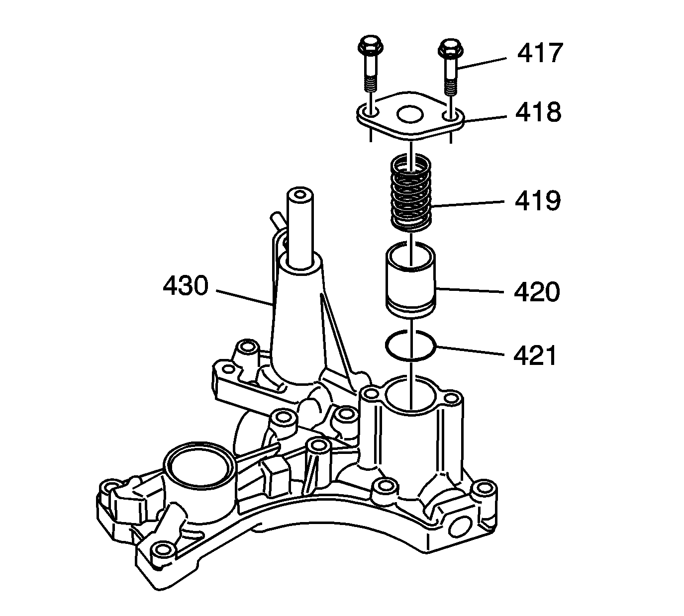
- Remove the 3rd accumulator piston bore cover bolts (417), then remove the following components:
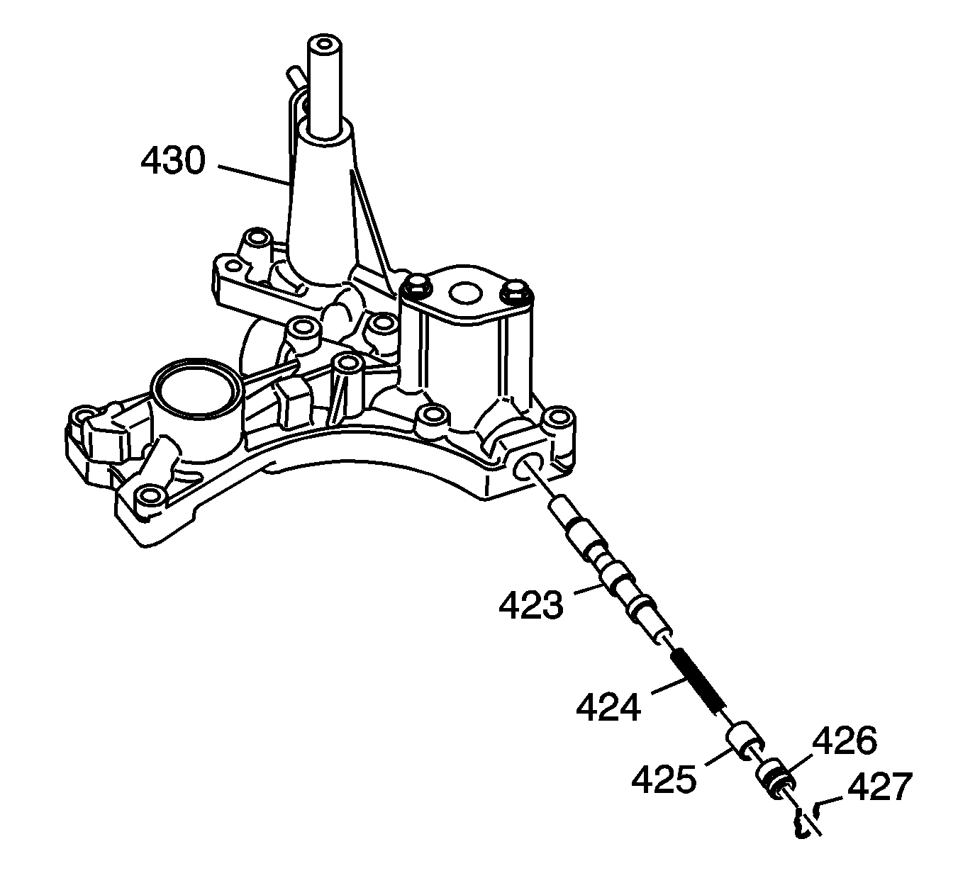
- Remove the valve bore plug retainer clip (427), then remove the following components:
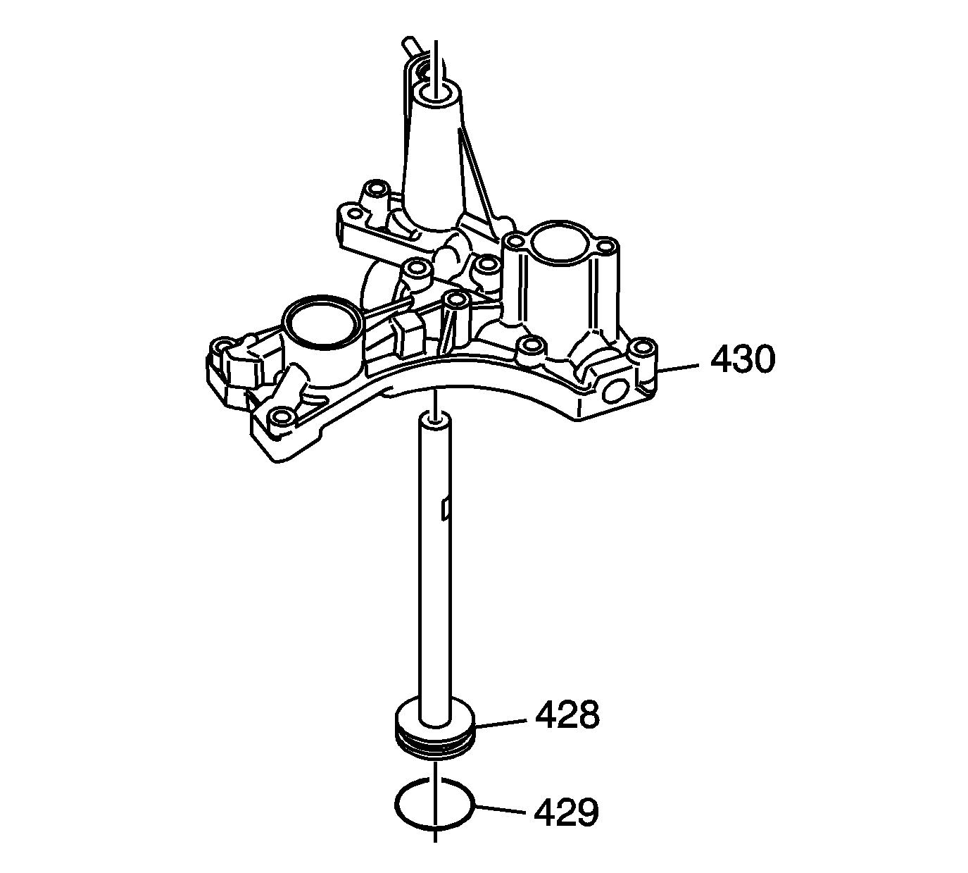
- Remove the reverse shift fork shaft (428)
- Remove the reverse shift fork shaft seal (429)
- Clean all parts thoroughly and then dry the components.
Caution: Some valves are under pressure. Cover the bores while removing the retainers and plugs or personal injury could result.
| • | Stator reaction spring (408) |
| • | Regulator valve outer spring (409) |
| • | Regulator valve inner spring (410) |
| • | Regulator pressure valve (415) |
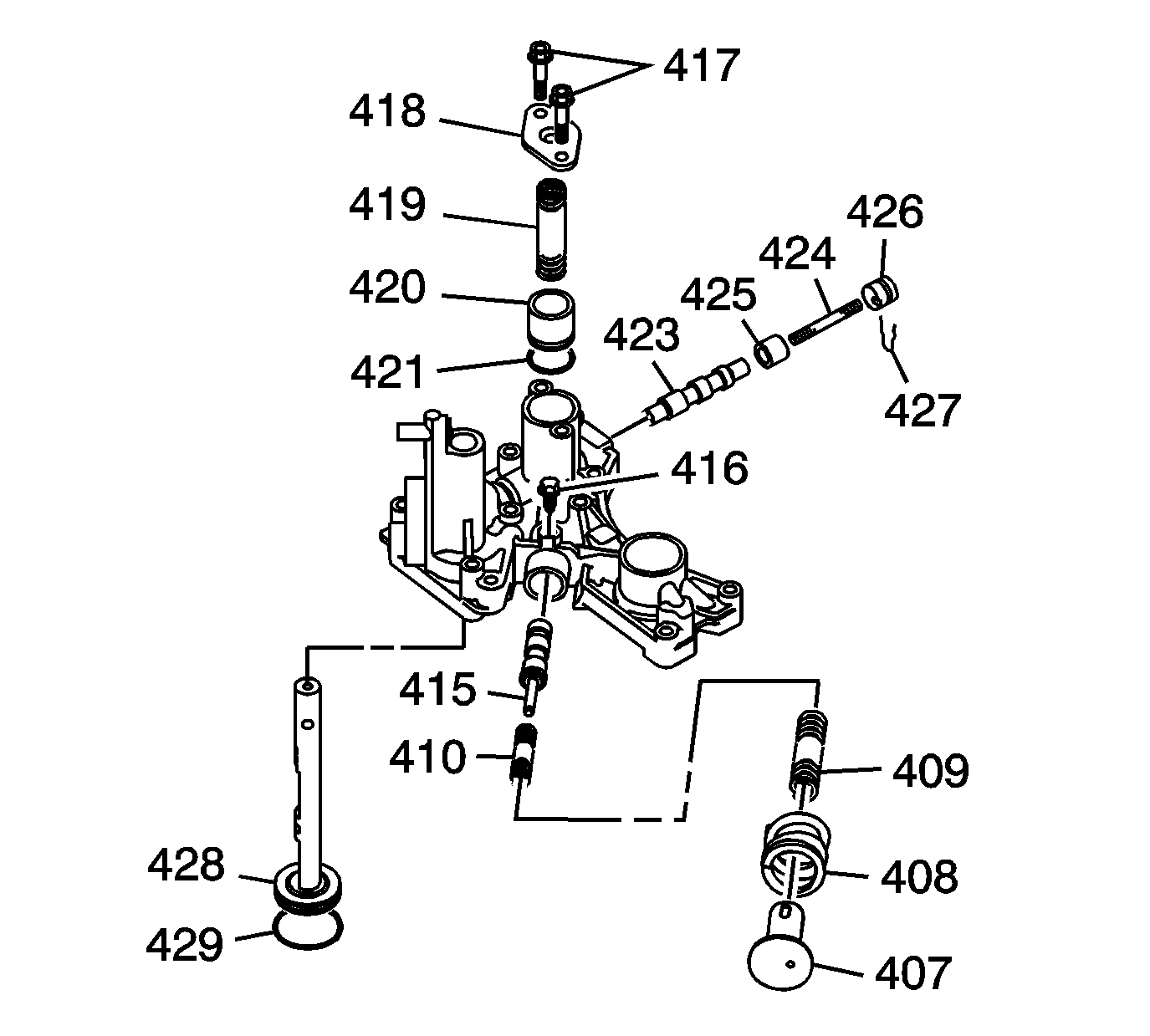
| • | 3rd accumulator piston bore cover (418) |
| • | 3rd clutch accumulator piston return spring (419) |
| • | 3rd clutch accumulator piston (420) |
| • | 3rd clutch accumulator piston O-ring (421) |
| • | Valve bore plug (426) |
| • | TCC lockup control valve return spring (424) |
| • | TCC lockup control valve spacer (425) |
| • | TCC lockup control valve (423) |
Inspection Procedure
- Inspect all valves for free movement. If any fail to slide freely, refer to General Valve Body Service Instructions .
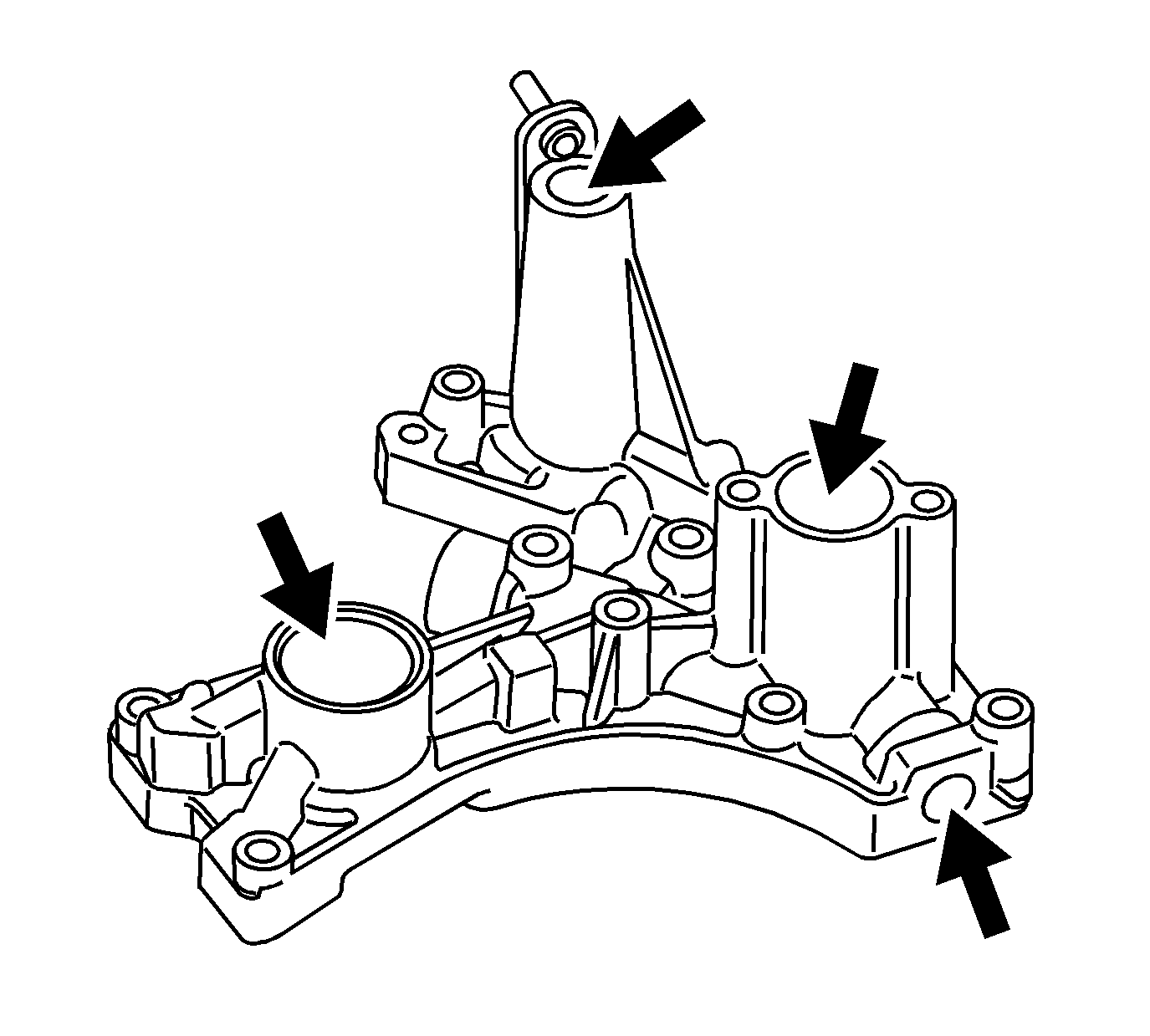
- Clean all of the regulator valve body bore passages.
- Lubricate the regulator valve body bores with automatic transmission fluid.
Assembly Procedure
- Lubricate all parts with automatic transmission fluid during assembly.
- Install a NEW 31 x 2.7 mm reverse shift fork O-ring seal (429) in the groove of the reverse shift fork (428).
- Install the reverse shift fork (428) into the regulator valve body (430) until it locks into the spring-loaded retainer ball.
- Install a new 21.2 x 2.4 mm 3rd clutch accumulator piston O-ring seal (421) on the 3rd clutch accumulator piston (420).
- Install the 3rd clutch accumulator piston (420).
- Install the 3rd clutch accumulator piston return spring (419).
- Install the 3rd clutch accumulator piston bore cover (418).
- Install the M6 x 1.0 x 30 mm 3rd clutch accumulator piston bore cover bolt (417).
- Install the pressure regulator valve (415) into the regulator valve body (430).
- Install the pressure regulator valve inner spring (410).
- Install the pressure regulator valve outer spring (409).
- Install the stator action spring (408).
- Align the slot in the pressure regulator valve spring cap (407) with the hole for the cap bolt.
- Press the spring cap into the regulator valve body.
- Install the pressure regulator valve spring cap guide M6 x 1.0 x 30 mm bolt (416).
- Install the TCC lock-up control valve (423) into the regulator valve body (430).
- Install the TCC lock-up control valve 49.2 mm return spring (424).
- Install the TCC lock-up control valve 15 mm spacer (425).
- Install the 15 mm valve bore plug (426).
- Install the valve bore plug retainer clip (427).
Notice: Refer to Fastener Notice in the Preface section.
Tighten
Tighten the piston bore cover bolt to 12 N·m (106 lb in)

Tighten
Tighten the regulator spring cap guide bolt to 12 N·m (106 lb in)
