For 1990-2009 cars only
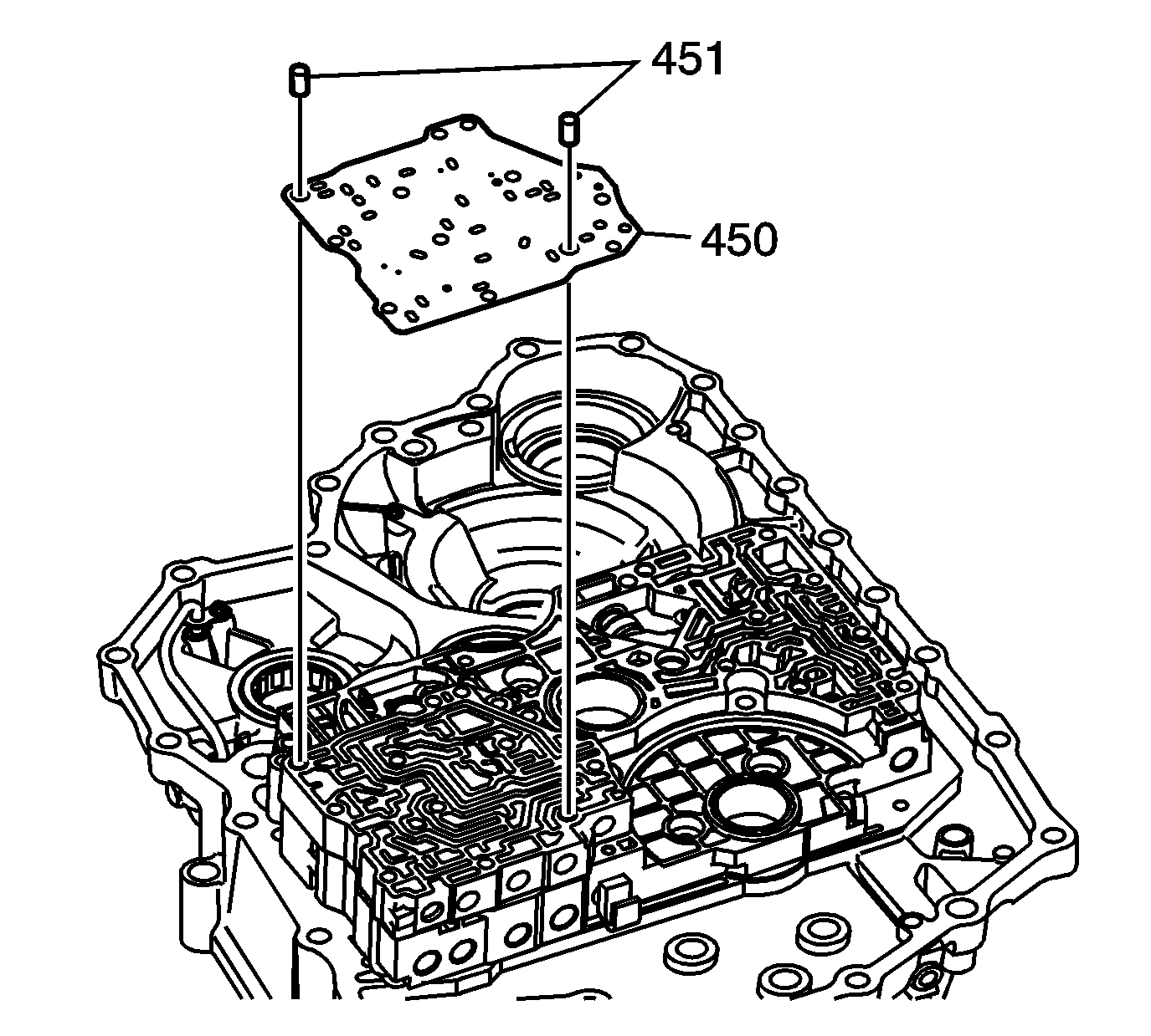
- Install 2 8 x 14 mm spacer plate locating pins (451) into the servo valve body assembly.
- Install the accumulator valve body spacer plate (450) on top of the servo valve body assembly.
- Place the manual shift detent roller (935) between the accumulator valve body spacer plate (450) and the accumulator valve body assembly (495).
- Insert the manual shift detent roller pin (937) through the following components:
- Seat the end of the manual shift detent roller pin (937) into the locating hole in the torque converter housing (150).
- Install the 8 x 62 mm 4th clutch apply fluid passage pipe (214) into the correct oil passage located in the top side of the control valve body assembly (250).
- Install the accumulator valve body (495) on top of the accumulator valve body spacer plate (450).
- Install the following accumulator valve body bolts:
- Tighten the bolts in the sequence shown.
- Install the following passage pipes into the accumulator valve body (495).
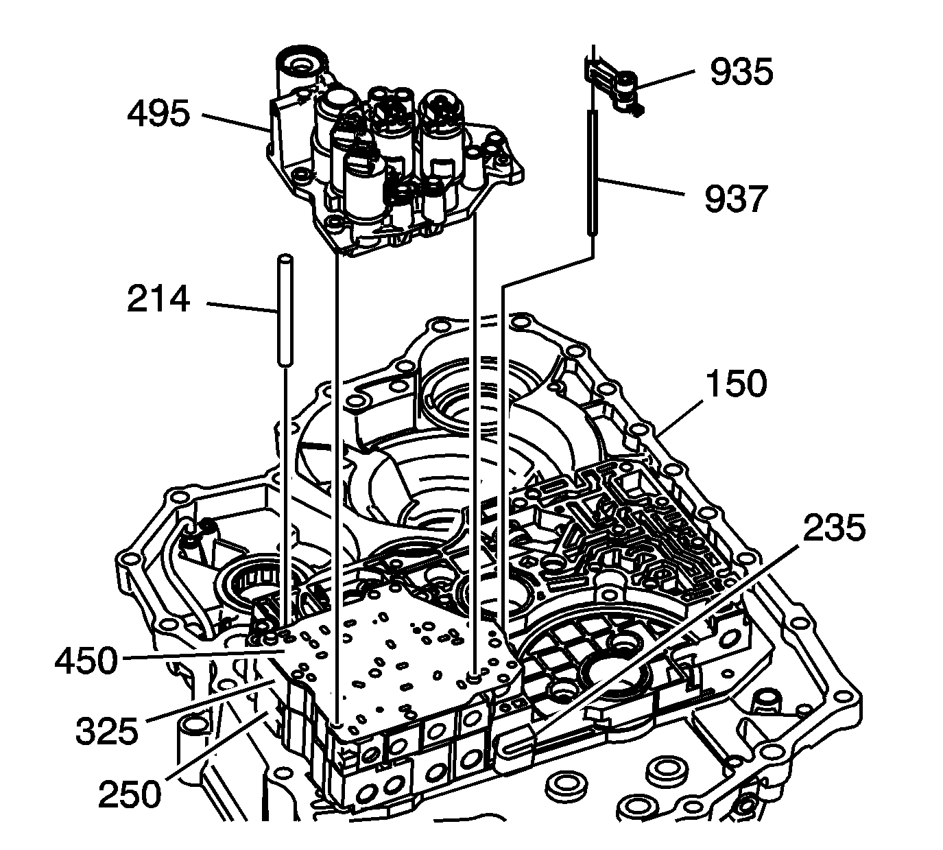
Important: The manual valve (235) must be turned in the correct position for the roller pin (937) to clear.
| • | Accumulator valve body spacer plate (450) |
| • | Servo valve body assembly (325) |
| • | Control valve body assembly (250) |
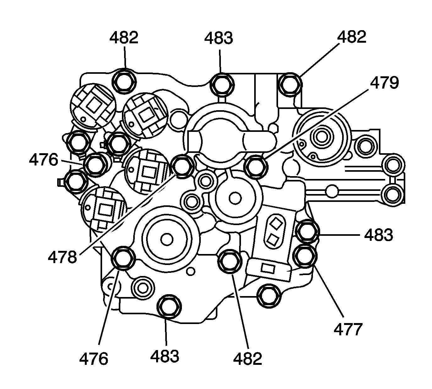
| • | A M6 x 1.0 x 60 mm bolt (477) |
| • | 3 M6 x 1.0 x 85 mm bolts (483) |
| • | 4 M6 x 1.0 x 95 mm bolts (482) |
| • | 2 M6 x 1.0 x 110 mm bolts (476) |
| • | A M6 x 1.0 x 125 mm bolt (479) |
| • | A M6 x 1.0 x 140 mm bolt (478) |
Notice: Refer to Fastener Notice in the Preface section.
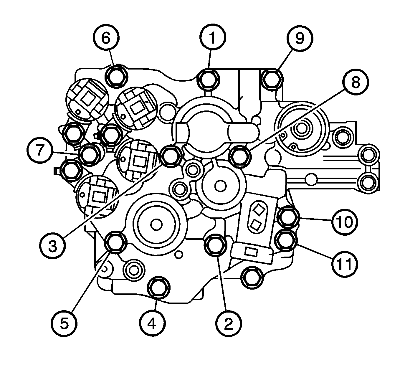
Tighten
Tighten all bolts to 12 N·m (106 lb in).
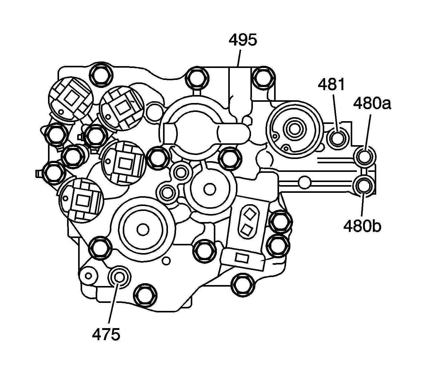
| • | Mainshaft lube fluid pipe (475) 8 x 85 mm |
| • | 1st clutch control fluid pipe (480a) 8 x 151.5 mm |
| • | Coast clutch fluid pipe (480b) 8 x 151.5 mm |
| • | 4th clutch control fluid pipe (481) 8 x 40 mm |
