Transaxle Inputs
TCC Brake Switch
The TCC Brake switch sends a signal to the powertrain control module (PCM) when the brake pedal is depressed. The switch is normally open when the brake pedal is in the released position. When the brake pedal is depressed, the switch is closed. If the torque converter clutch (TCC) is engaged when the brake pedal is depressed, the PCM will disengage the TCC.
Transmission Fluid Temperature (TFT) Sensor
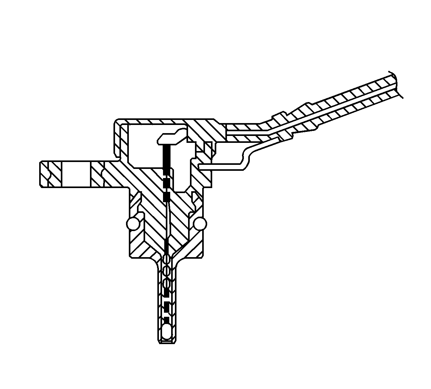
The automatic transmission fluid temperature (TFT) sensor is a thermistor. The powertrain control module (PCM) supplies a 5 volt reference signal to the sensor. When the transmission fluid is cold, the sensor resistance is high and the PCM senses a high signal voltage. As the transmission fluid warms, the sensor resistance lowers and the PCM senses lower voltage. The PCM uses the TFT reading in order to control the torque converter clutch (TCC), line pressure adjustments, and temperature compensated shifts. Refer to Transmission Fluid Temperature Sensor Specifications
Input Speed Sensor (ISS)
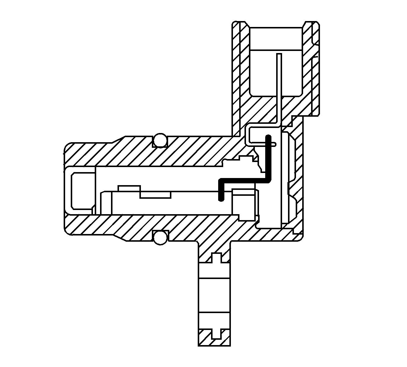
The automatic transmission input shaft speed (AT ISS) sensor is a three-wire magnetic pick-up sensor that is mounted externally to the transmission. The AT ISS utilizes the main idler gear teeth, located on the mainshaft, to generate a voltage signal of varying frequency that corresponds to the rotational speed of the mainshaft. The AT ISS signal is sent to the powertrain control module (PCM) and is used to calculate the vehicle speed. Simultaneously, the automatic transmission output speed shaft (AT OSS) sensor signal is used to calculate the vehicle speed. The PCM compares the vehicle speed calculated from both speed sensors and uses this comparison for diagnosis of the speed sensors.
Output Speed Sensor (OSS)
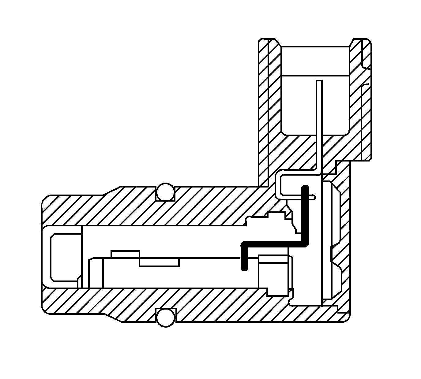
The automatic transmission output shaft speed (AT OSS) sensor is a three-wire magnetic pick-up sensor that is mounted externally to the transmission. The OSS utilizes the gear teeth, located on the output shaft, to generate a voltage signal of varying frequency that corresponds to the rotational speed of the output shaft. The OSS signal is sent to the PCM and is used to calculate the vehicle speed. Simultaneously, the automatic transmission input shaft speed sensor (AT ISS) signal is used to calculate the vehicle speed. The PCM compares the vehicle speed calculated from both speed sensors and uses this comparison for diagnosis of the speed sensors.
Park/Neutral Position (PNP) Switch
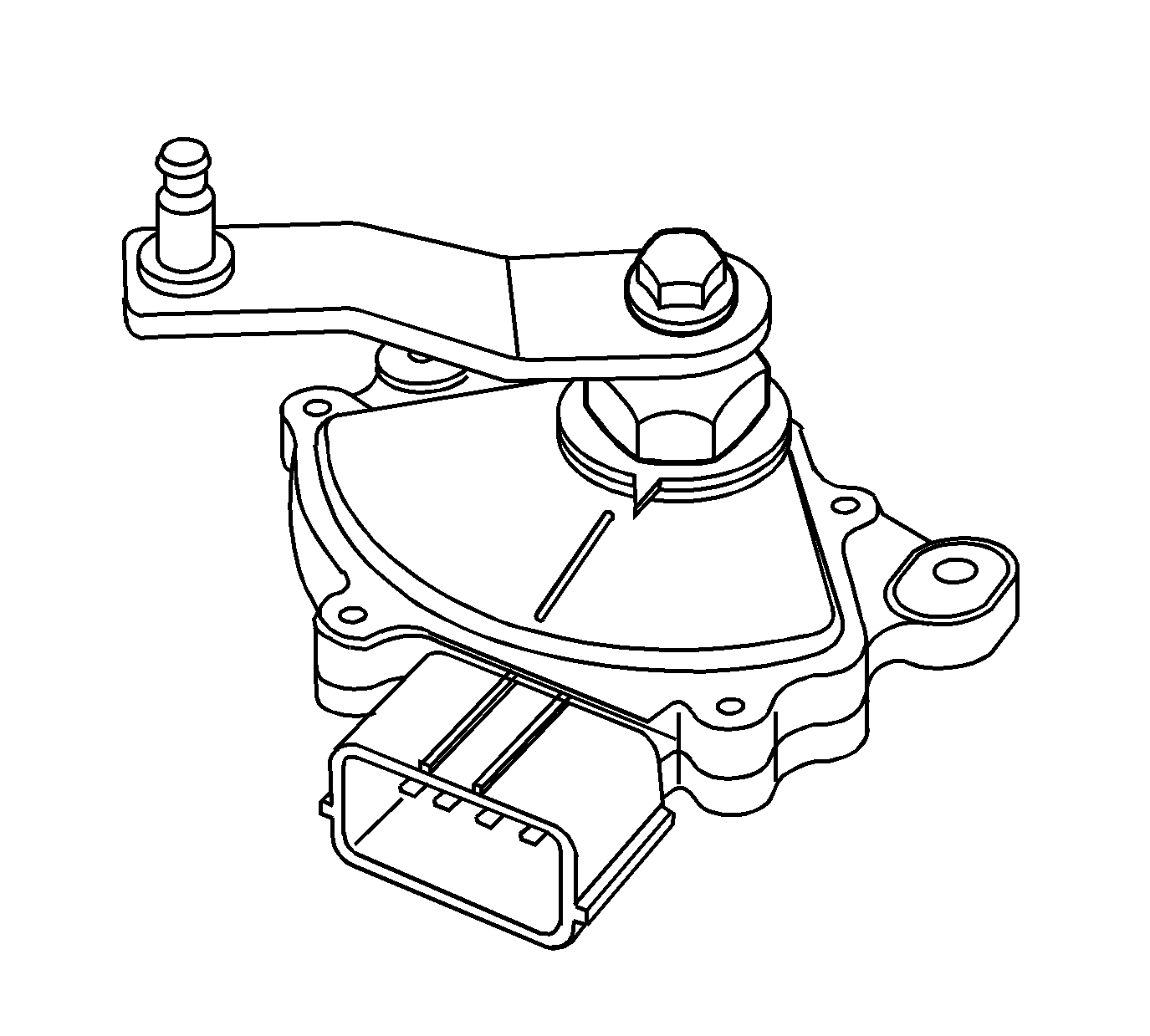
The park/neutral position switch assembly and is mounted on the transmission manual shaft. The transmission range (TR) switch is part of the park/neutral position switch assembly. The TR switch is a multi-signal switch. The powertrain control module (PCM) supplies ignition voltage to the TR switch on 7 signal circuits, P, R, N, D, I, L, and Forward Range. Each gear selector lever position grounds one or more of the signal circuits in a unique pattern. In order to determine the gear range selected by the driver, the PCM compares the voltage combination on the signal circuits to a TR switch combination table stored in memory. Refer to Transmission Range Switch Logic .
Transaxle Outputs
Torque Converter Clutch (TCC) Enable Solenoid
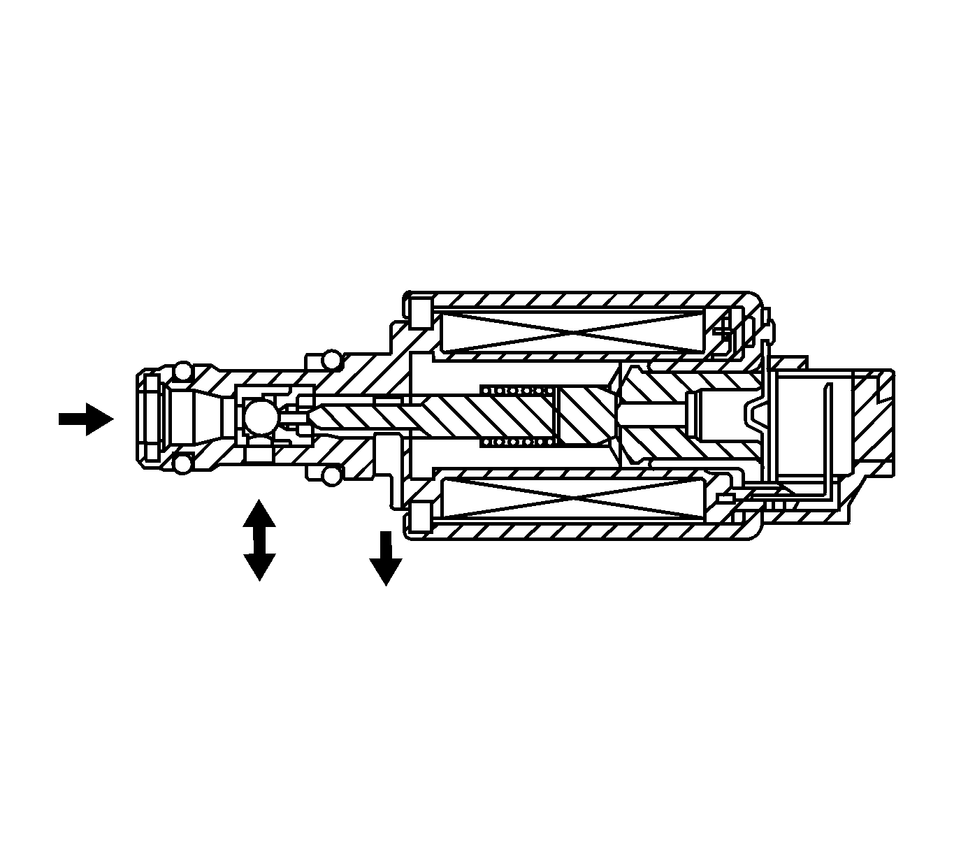
The torque converter clutch (TCC) enable solenoid valve is used with the lock-up shift valve, lock-up control valve and lock-up timing valve in order to control TCC apply and release in response to the powertrain control module (PCM) commands. When it is energized, it allows the fluid pressure from the TCC pressure control (PC) solenoid valve to be exhausted. When it is de-energized, it allows the fluid pressure to apply to the lock-up shift valve. The PCM has an internal diagnostic circuit to monitor the voltage level to the TCC enable solenoid valve, and receives a return signal.
Shift Solenoid Valve A,B,C (1, 2, 3)

The shift solenoid (SS) valves are normally open valves that mounts into the transmission case. The SS valves control the modulator pressure to the shift valves, as commanded by the powertrain control module (PCM). The SS valves are all identical. These SS valves work together in a combination of ON and OFF sequences in order control various shift valves. The PCM uses numerous inputs to determine which solenoid state combination the transmission should be in. Refer to Shift Solenoid Valve State and Gear Ratio .
Clutch Pressure Control (CPC) Solenoid Valve A, B (1,2) and TCC Pressure Control Solenoid
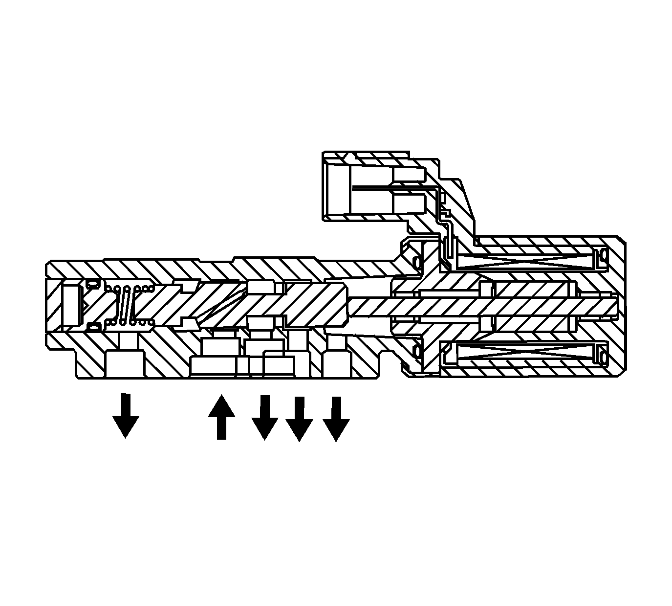
| • | The clutch pressure control (PC) solenoid valve 1 regulates modulator pressure based on the current flow commanded from the powertrain control module (PCM). The PCM outputs varying amount of amperage as necessary for gear change, and the PC solenoid valves supply oil pressure proportional to the current to the PC valve 1. The PCM monitors the current flowing through the solenoid and performs feedback control. |
| • | The clutch pressure control (PC) solenoid valve 2 regulates modulator pressure based on the current flow commanded from the powertrain control module (PCM). The PCM outputs varying amount of amperage as necessary for gear change, and the PC solenoid valves supply oil pressure proportional to the current to the PC valve 2. The PCM monitors the current flowing through the solenoid and performs feedback control. |
| • | The TCC pressure control (PC) solenoid valve regulates modulator pressure based on the current flow commanded from the powertrain control module (PCM). The PCM outputs varying amount of amperage as necessary for TCC application, and the PC solenoid valves supply oil pressure proportional to the current to the PC valve 2. The PCM monitors the current flowing through the solenoid and performs feedback control. |
The PCM measures the current amperage flowing through the PC solenoid valves and uses feedback control to compensate the difference between the actual current amperage and the commanded amperage.
3rd Clutch Oil Pressure Switch
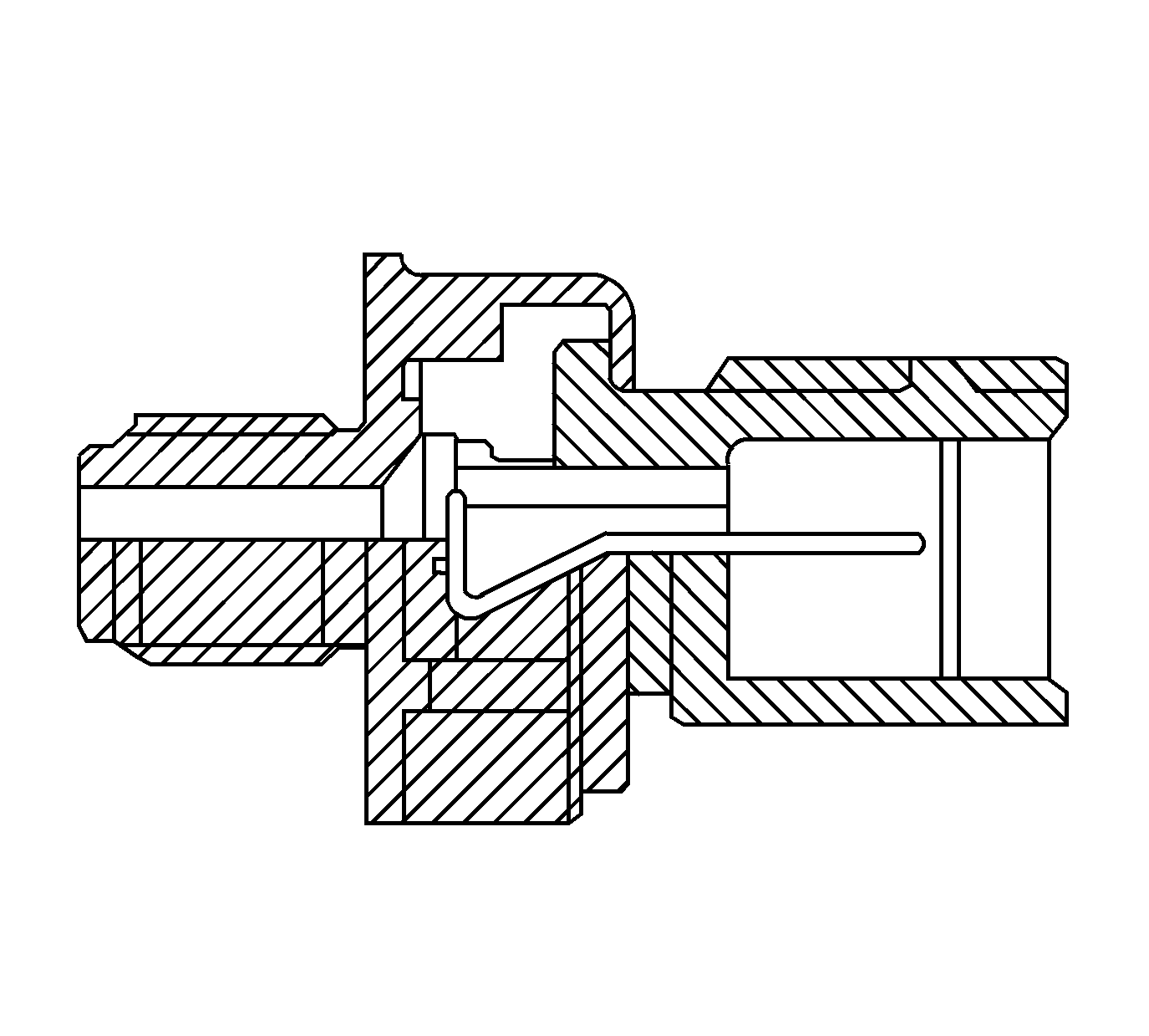
The 3rd clutch pressure switch is located in the hydraulic passage to the 3rd clutch. When oil pressure is supplied to the 3rd clutch, the switch is grounded. When oil pressure is not supplied, the switch is open. The PCM receives the signal from the 3rd clutch pressure switch to detect the fluid pressure status, in order to reduce the shift shock upon shifting to 3rd gear, 2nd to 3rd, or 4th to 3rd.
4th Clutch Oil Pressure Switch

The 4th clutch pressure switch is located in the hydraulic passage to the 4th clutch. When oil pressure is supplied to the 4th clutch, the switch is grounded, LOW. When oil pressure is not supplied, the switch is open, HI. The PCM receives the signal from the 4th clutch pressure switch to detect the fluid pressure status, in order to reduce the shift shock when shifting into 4th gear, from 3rd to 4th or 5th to 4th.
