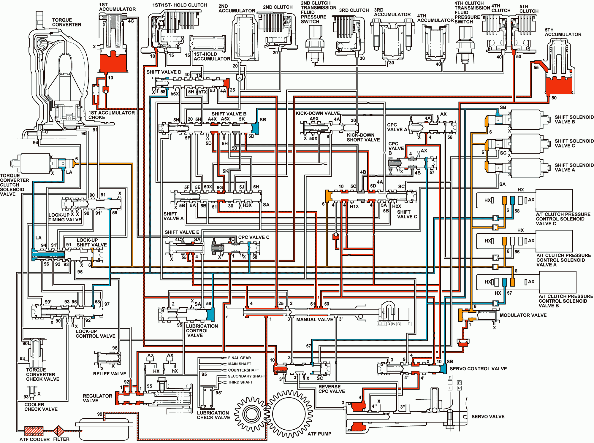
Distribution of Hydraulic Pressure
As the engine turns, the automatic transmission fluid (ATF) pump starts to operate. ATF is drawn through the ATF filter and discharged into the hydraulic circuit. ATF flowing from the ATF pump becomes line pressure that is regulated by the regulator valve. Torque converter pressure, from the regulator valve, enters the torque converter through the lock-up shift valve and is discharged from the torque converter. The torque converter check valve prevents torque converter pressure from rising.
The powertrain control module (PCM) controls the shift solenoid valves ON and OFF. The shift solenoid valves control shift solenoid pressure to the shift valves. Applying shift solenoid pressure to the shift valves moves the position of the shift valve, and switches the port of hydraulic pressure. The PCM also controls the automatic transmission clutch pressure control (AT CPC) solenoid valves A and B.
The AT CPC solenoid valves A and B regulate the AT CPC solenoid pressure and apply the AT CPC solenoid pressure to CPC valves A and B. When shifting between upper gear and lower gear, the clutch is engaged by pressure from the CPC pressure mode.
The PCM controls one of the shift solenoid (SS) valves to move the position of the shift valve. This movement switches the port of the CPC and line pressure. Line pressure is then applied to the clutch, and the CPC pressure is intercepted.
When shifting is completed, the clutch is engaged with line pressure.
Port No. | Type of Pressure | Port No. | Type of Pressure | Port No. | Type of Pressure | ||||||||||||
|---|---|---|---|---|---|---|---|---|---|---|---|---|---|---|---|---|---|
1 | Line | 5N | CPC A or Line | 56 | LS A | ||||||||||||
2 | Line | 5D | CPC B or Line | 57 | LS B | ||||||||||||
3 | Line | 5G | CPC B or Line | 58 | LS C | ||||||||||||
3' | Reverse CPC or Line | 5K | CPC B or Line | 90 | Torque Converter | ||||||||||||
3" | Reverse CPC or Line | 6 | Modulate | 90' | Torque Converter | ||||||||||||
4 | Line | SA | SH A | 91 | Torque Converter | ||||||||||||
4' | Line | SB | SH B | 91' | Torque Converter | ||||||||||||
4" | Line | SC | SH C | 92 | Torque Converter | ||||||||||||
4A | CPC A | LA | LC A | 93 | ATF cooler | ||||||||||||
4B | CPC B | 9 | Line | 94 | Torque Converter | ||||||||||||
4C | CPC C | 10 | 1st Clutch | 95 | Lubrication | ||||||||||||
5B | CPC A | 15 | 1st Hold Clutch | 95' | Lubrication | ||||||||||||
5C | CPC B | 20 | 2nd Clutch | 96 | Torque Converter | ||||||||||||
5H | CPC B | 25 | Line | 97 | Torque Converter | ||||||||||||
5J | CPC B | 30 | 3rd Clutch | 99 | Suction | ||||||||||||
5A | CPC A or Line | 40 | 4th Clutch | X | Drain | ||||||||||||
5E | CPC A or Line | 50 | 5th Clutch | HX | High Position Drain | ||||||||||||
5F | CPC A or Line | 51 | 5th Clutch | hX | High Position drain | ||||||||||||
5M | CPC A or Line | 55 | CPC C or Line | AX | Air Drain | ||||||||||||
| |||||||||||||||||
D Position: Driving in 5th gear
The PCM turns shift solenoid (SS) valve C ON, and controls AT CPC solenoid valve A to release LS A pressure (56) in CPC valve A. SS valve A stays ON, and B stays OFF. The release of LS A pressure (56) in CPC valve A releases CPC A pressure in the 4th clutch pressure circuit. SS valve C is turned ON, and SH C pressure (SC) in the right side of shift valve C is released. SS C is then moved to the right side to switch the port of line pressure and CPC pressure. Line pressure (4), from the manual valve, becomes 5th clutch pressure (50) at the manual valve, via shift valve C, B, and A, and flows to the 5th clutch. The 5th clutch pressure is changed to line pressure mode by switching the position of shift valve C. The 5th clutch is engaged securely, and the 1st clutch is also engaged. No power is transmitted because of the one-way clutch.
When used, ''left'' or ''right'' indicates direction on the hydraulic circuit.
Drive Range Fifth Gear - TCC Released

