Gear Operation
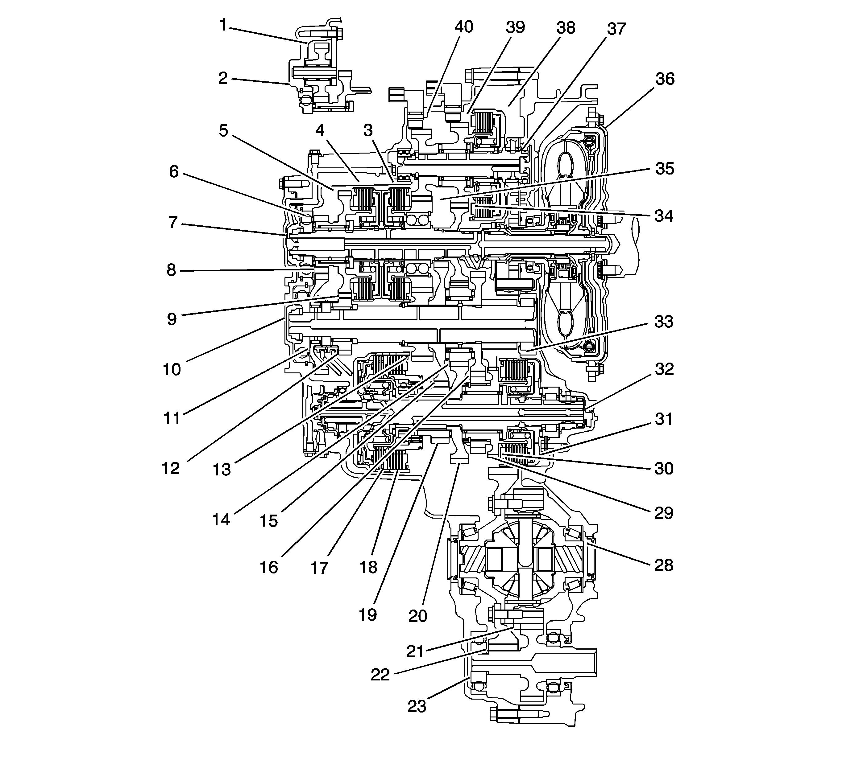
Gears on the Mainshaft (7):
| • | 4th gear (35) is engaged/disengaged with the mainshaft (7)
by the 4th clutch (3). |
| • | 5th gear (5) is engaged/disengaged with the mainshaft (7)
by the 5th clutch (4). |
| • | Reverse gear (6) is engaged/disengaged with the mainshaft (7)
by the 5th clutch (4). |
| • | 3rd gear (34) is splined with the mainshaft (7) and
rotates with the mainshaft (7). |
Gears on the Output Shaft (10):
| • | Final gear is integral with the output shaft (10). |
| • | 1st gear (15), 2nd gear (16), and 4th gear (13)
are splined with the output shaft (10), and rotate with the output shaft (10). |
| • | 5th gear (12) and reverse gear (8) rotate freely
from the output shaft (10). The reverse selector engages 5th gear (12)
and reverse gear (8) with the reverse selector hub (9). The reverse
selector hub (9) is splined to the output shaft (10) so 5th gear (12)
and reverse gear (8) engage with the output shaft (10). |
| • | Idler gear (4) is located over the 2nd gear (16),
and rotates freely from the output shaft (10). |
Gears on the 1st/2nd Clutch Shaft (32):
| • | 1st gear (19) is engaged/disengaged with the 1st/2nd clutch
shaft (32) by the 1st clutch (18). 1st gear (19)
is engaged with the 1st/2nd clutch shaft (32) by the one-way clutch
and the coast clutch (17) when decelerating for engine braking. |
| • | 2nd gear (29) is engaged/disengaged with the 1st/2nd clutch
shaft (32) by the 2nd clutch (31). |
| • | Drive gear (20) is splined with the 1st/2nd clutch shaft (32),
and rotates with the 1st/2nd clutch shaft (32). |
| • | Park gear (30) is integral with the 2nd gear (29). |
Gears on the 3rd Clutch Shaft (37):
| • | 3rd gear (39) is engaged/disengaged with the 3rd clutch
shaft (37) by the 3rd clutch (38). |
| • | 4th gear (40) is splined with the 3rd gear (39). |
PNDI Power Flow
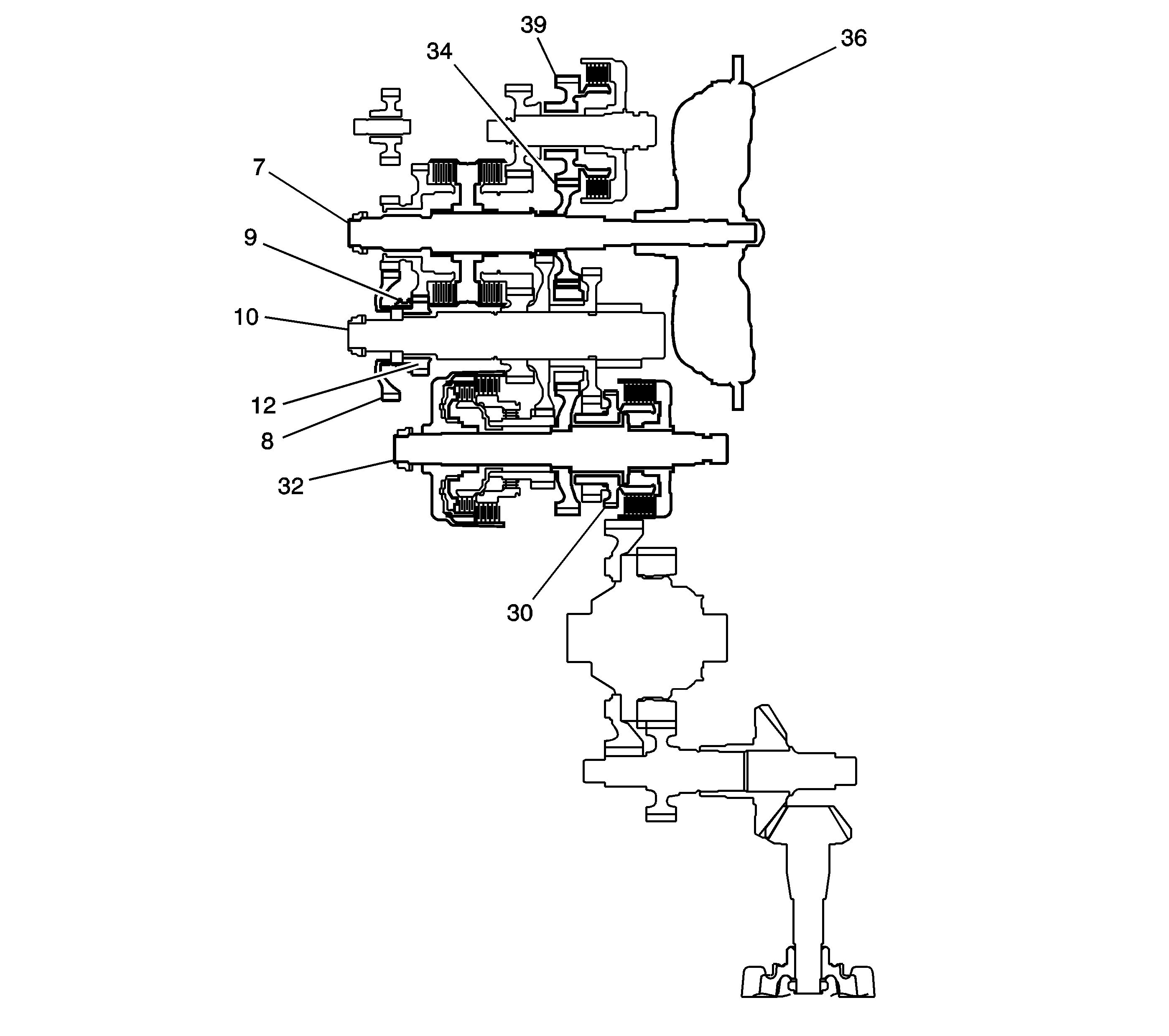
P Position
Hydraulic pressure is not applied to the clutches. Power is not transmitted
to the output shaft (10). The park pawl interlocking the park gear (30)
locks the output shaft (10).
N Position
Engine power transmitted from the mainshaft (7) drives the mainshaft
3rd gear (34), the 3rd shaft 3rd gear (39), but
hydraulic pressure is not applied to the clutches. Power is not transmitted to the
output shaft (10). In the N position, the position of the reverse selector
differs according to whether the shift lever was shifted from the D or P position
in the following ways:
| • | When shifted from the D position, the reverse selector engages
with the output shaft 5th gear (12) and the reverse selector hub (9),
and the output shaft 5th gear (12) engages with the output shaft (10). |
| • | When shifted from the R position, the reverse selector engages
with the output shaft reverse gear (8) and the reverse selector hub (9),
and the reverse gear (8) engages with the output shaft (10). |
D or I Position
In the D position the optimum gear is automatically selected from the
1st, 2nd, 3rd, 4th, and 5th gears, and in the I position the optimum gear is
automatically selected from the 1st, 2nd and 3rd gears according to conditions such
as the balance between the throttle opening and vehicle speed.
1st Gear Power Flow
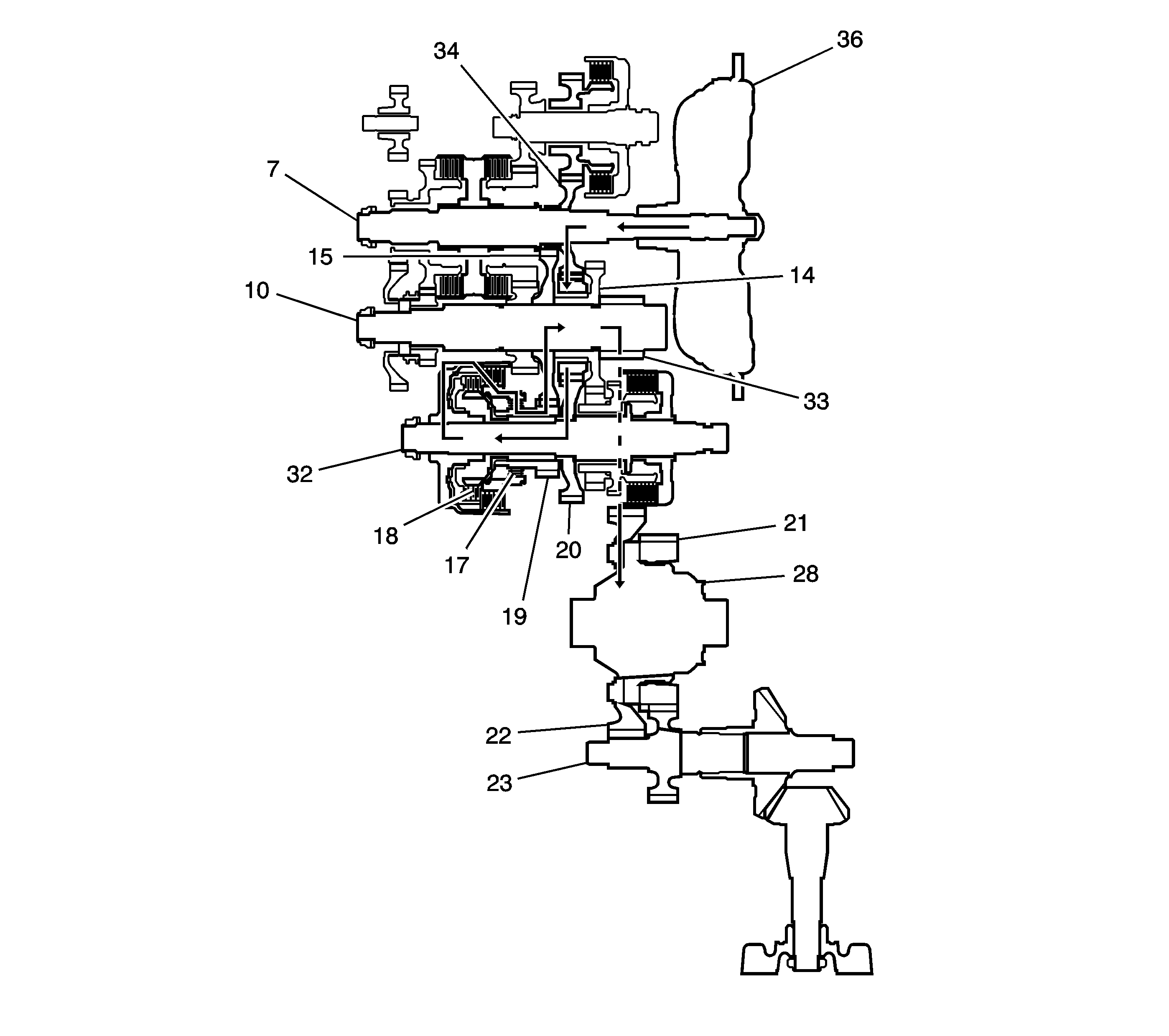
| • | Hydraulic pressure is applied to the 1st clutch (18), then
the 1st clutch (18) engages the 1st/2nd clutch shaft 1st gear (19)
with the 1st/2nd clutch shaft (32) by the coast/one-way clutch (17). |
| • | The mainshaft 3rd gear (34) drives the 1st/2nd clutch shaft (32)
via the output shaft idler gear (14) and the 1st/2nd clutch shaft drive gear (20). |
| • | The 1st/2nd clutch shaft 1st gear (19) drives the output
shaft 1st gear (15) and the output shaft (10). |
| • | IF AWD, power is transmitted to the final drive gear (33), which
in turn drives the final driven gear (22) and the transfer drive gear (21).
Then the transfer output shaft (23) drives the transfer case hypoid drive gear/shaft
and the transfer output shaft/hypoid gear. |
| • | If FWD, power is transmitted to the final drive gear (33) which
in turn drives the final driven gear (22), which turns the front differential
assembly (28). |
2nd Gear Power Flow
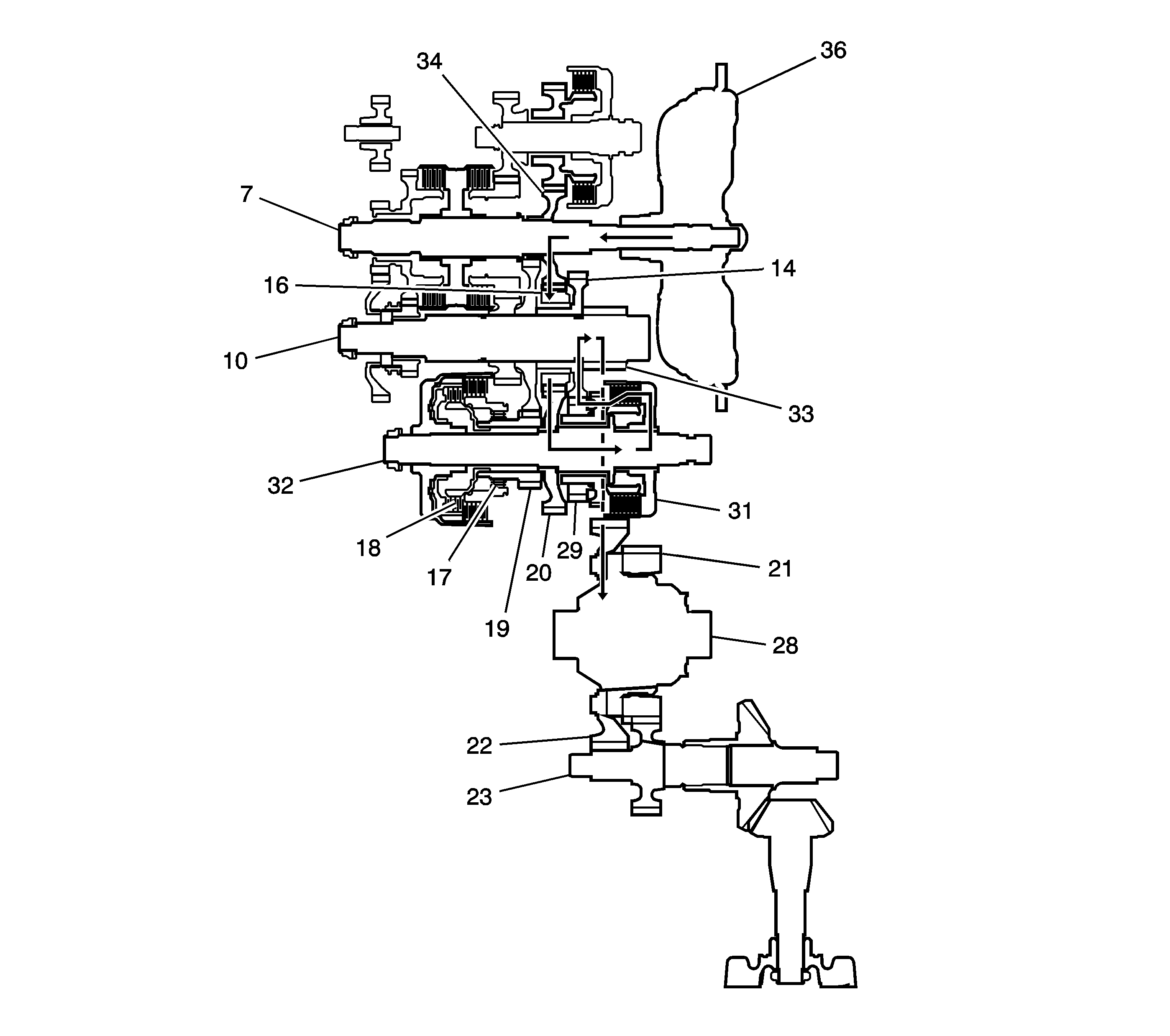
| • | Hydraulic pressure is applied to the 2nd clutch (31), then
the 2nd clutch (31) engages the 1st/2nd clutch shaft 2nd gear (29)
with the 1st/2nd clutch shaft (32). |
| • | The mainshaft 3rd gear (34) drives the 1st/2nd clutch shaft (32)
via the output shaft idler gear (14) and the 1st/2nd clutch shaft drive gear (20). |
| • | The 1st/2nd clutch shaft 2nd gear (29) drives the output
shaft 2nd gear (16) and the output shaft (10). |
| • | IF AWD, power is transmitted to the final drive gear (33), which
in turn drives the final driven gear (22) and the transfer drive gear (21).
Then the transfer output shaft (23) drives the transfer case hypoid drive gear/shaft
and the transfer output shaft/hypoid gear. |
| • | If FWD, power is transmitted to the final drive gear (33) which
in turn drives the final driven gear (22), which turns the front differential
assembly (28). |
| • | Hydraulic pressure is also applied to the 1st clutch (18),
but since the rotation speed of 2nd gear (16) exceeds that of 1st gear (19),
power from 1st gear (19) is cut off at the coast/one-way clutch (17). |
3rd Gear Power Flow
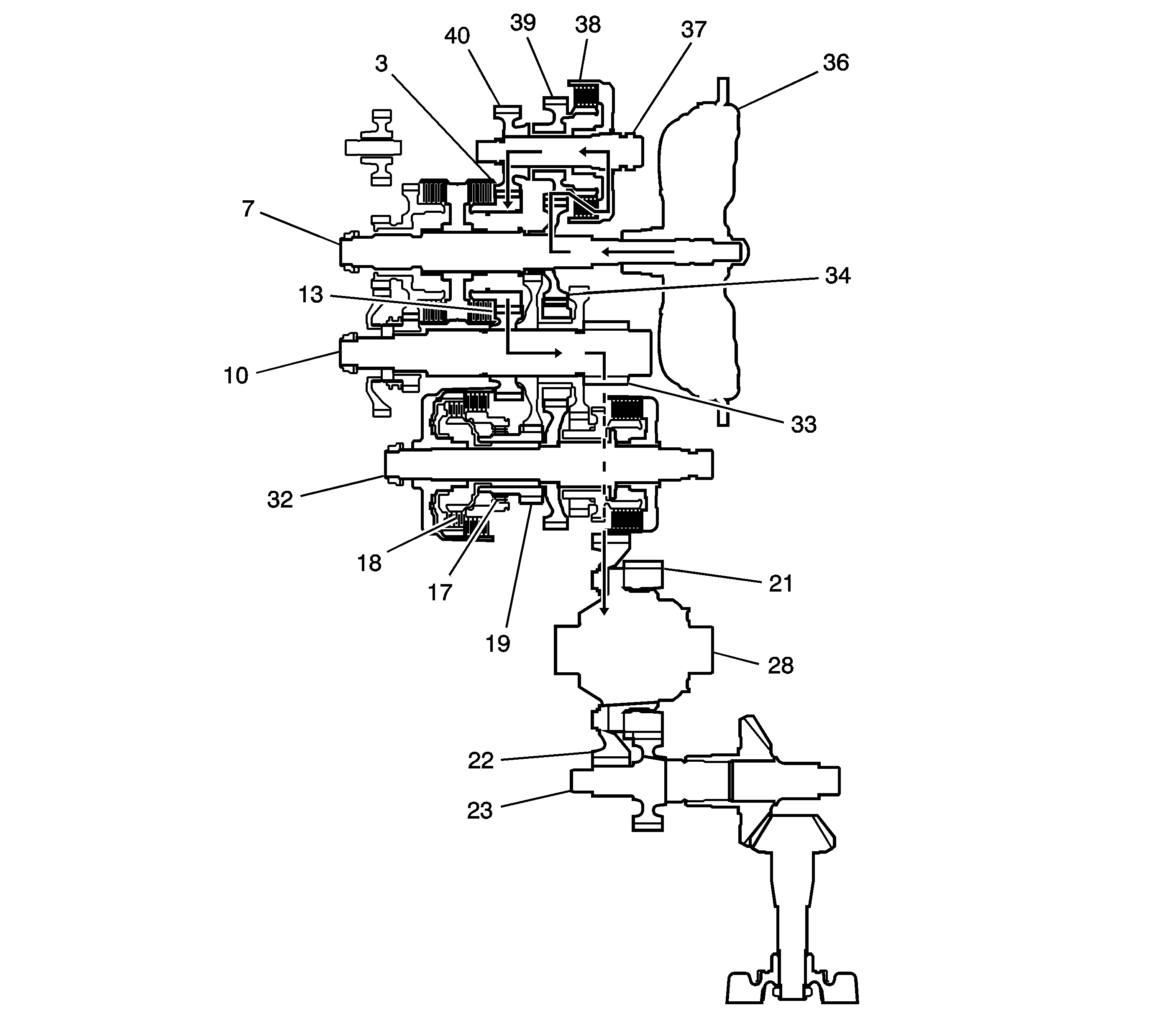
| • | Hydraulic pressure is applied to the 3rd clutch (38), then
the 3rd clutch (38) engages the third shaft 3rd gear (39)
with the third shaft (37). |
| • | The mainshaft 3rd gear (34) drives the third shaft 4th gear (40)
via the 3rd gear (39) and the 3rd clutch (38). |
| • | The 3rd shaft 4th gear (40) drives the output shaft
4th gear (13) and the output shaft (10) via the mainshaft 4th gear (34). |
| • | IF AWD, power is transmitted to the final drive gear (33), which
in turn drives the final driven gear (22) and the transfer drive gear (21).
Then the transfer output shaft (23) drives the transfer case hypoid drive gear/shaft
and the transfer output shaft/hypoid gear. |
| • | If FWD, power is transmitted to the final drive gear (33) which
in turn drives the final driven gear (22), which turns the front differential
assembly (28). |
| • | Hydraulic pressure is also applied to the 1st clutch (18),
but since the rotation speed of 3rd gear (34) exceeds that of 1st gear (19),
power from 1st gear (19) is cut off at the coast/one-way clutch (17). |
4th Gear Power Flow
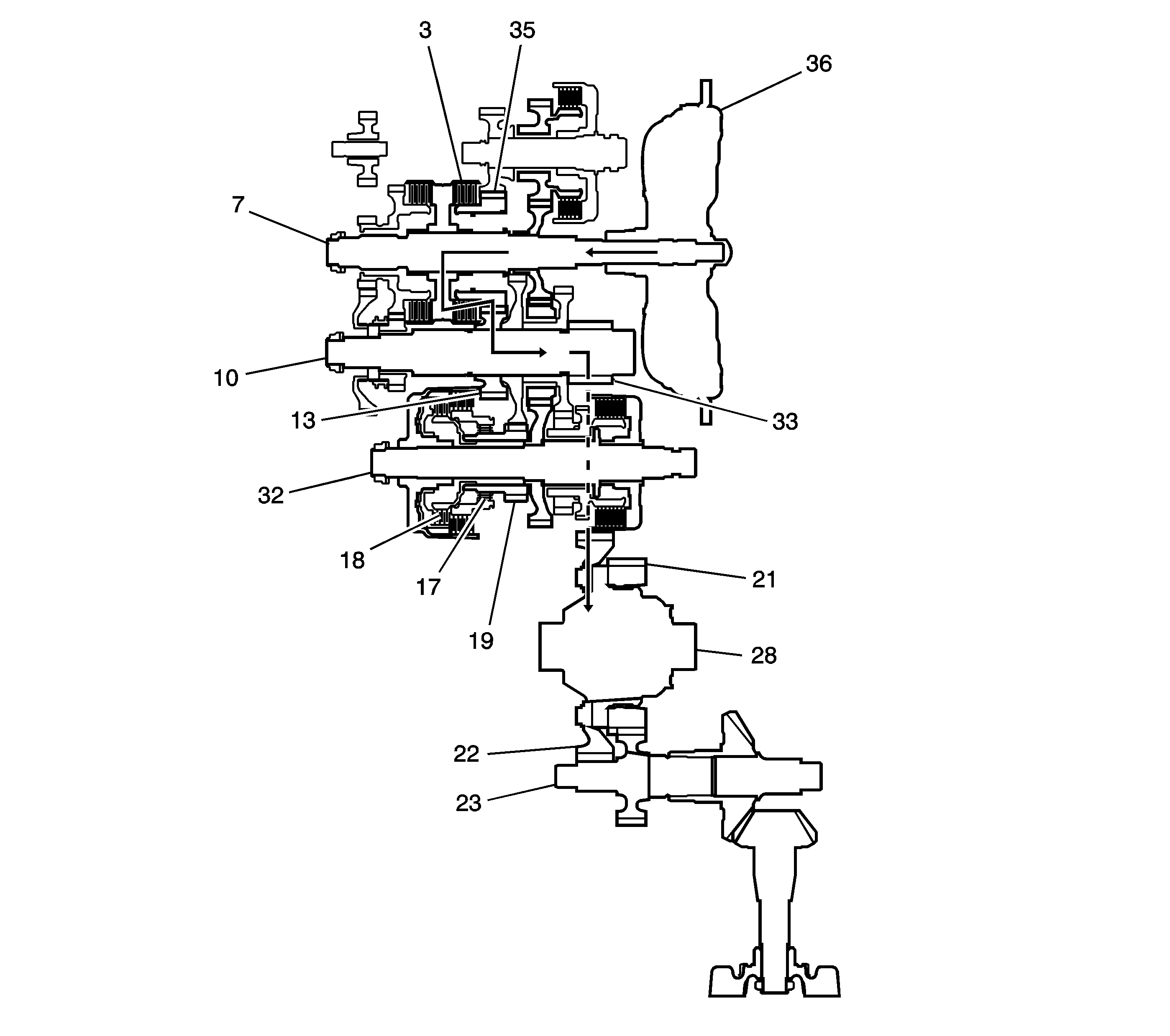
| • | Hydraulic pressure is applied to the 4th clutch (3), then
the 4th clutch (3) engages the mainshaft 4th gear (35)
with the mainshaft (7). |
| • | The mainshaft 4th gear (35) drives the output shaft 4th gear (13)
and the output shaft (10). |
| • | IF AWD, power is transmitted to the final drive gear (33), which
in turn drives the final driven gear (22) and the transfer drive gear (21).
Then the transfer output shaft (23) drives the transfer case hypoid drive gear/shaft
and the transfer output shaft/hypoid gear. |
| • | If FWD, power is transmitted to the final drive gear (33) which
in turn drives the final driven gear (22), which turns the front differential
assembly (28). |
| • | Hydraulic pressure is also applied to the 1st clutch (18),
but since the rotation speed of 4th gear (35) exceeds that of 1st gear (19),
power from 1st gear (19) is cut off at the coast/one-way clutch (17). |
5th Gear Power Flow
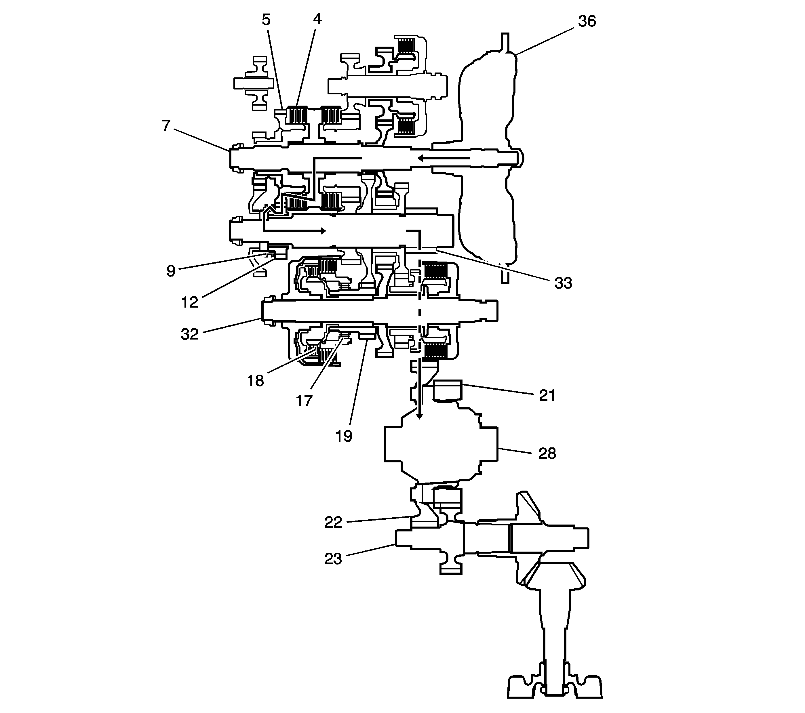
| • | Hydraulic pressure is also applied to the 5th clutch (4),
then the 5th clutch (4) engages the mainshaft 5th gear (5)
with the mainshaft (7). |
| • | The mainshaft 5th gear (5) drives the output shaft 5th gear (12),
which drives the reverse selector hub (9) and the output shaft. |
| • | IF AWD, power is transmitted to the final drive gear (33), which
in turn drives the final driven gear (22) and the transfer drive gear (21).
Then the transfer output shaft (23) drives the transfer case hypoid drive gear/shaft
and the transfer output shaft/hypoid gear. |
| • | If FWD, power is transmitted to the final drive gear (33) which
in turn drives the final driven gear (22), which turns the front differential
assembly (28). |
| • | Hydraulic pressure is also applied to the 1st clutch (18),
but since the rotation speed of 5th gear (12) exceeds that of 1st gear (19),
power from 1st gear (19) is cut off at the coast/one-way clutch (17). |
L Gear Power Flow
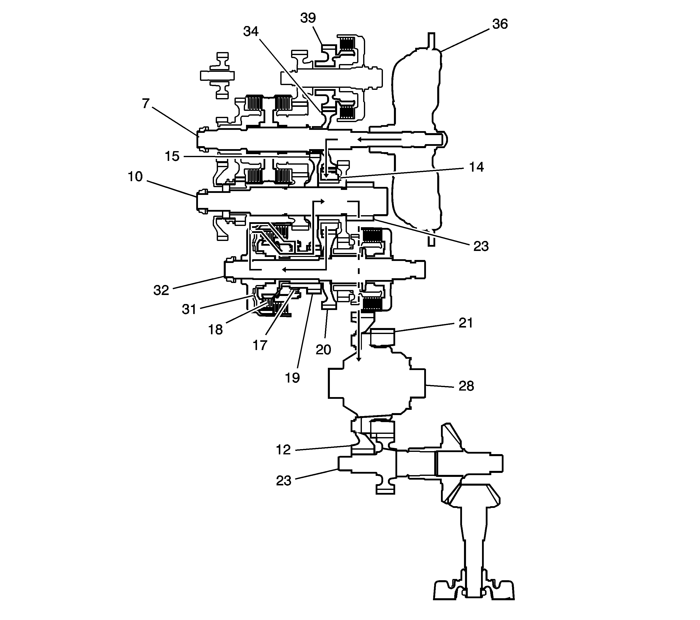
In the L position, the optimum gear is automatically selected between
1st and 2nd. In the 1st gear in L range, however, the hydraulic pressure
is applied to the coast/one-way clutch (17) in addition to the 1st clutch (18).
The power flow of 2nd gear is the same as the other forward ranges. The power
flow in the 1st gear when accelerating is as follows:
| • | Hydraulic pressure is applied to the 1st clutch (18), then
the 1st clutch (18) engages the 1st/2nd clutch shaft 1st gear (19)
with the 1st/2nd clutch shaft (32) by the coast/one-way clutch (17). |
| • | Hydraulic pressure is also applied to the coast/one-way clutch (17),
and the coast/one-way clutch (17) engages the 1st/2nd clutch shaft 1st gear (19)
with the 1st/2nd clutch shaft (32). |
| • | The mainshaft 3rd gear (34) drives the 1st/2nd clutch shaft (32)
via the counter shaft idler gear (14) and the 1st/2nd clutch shaft drive gear (20). |
| • | The 1st/2nd clutch shaft 1st gear (19) drives the output
shaft 1st gear (15) and the output shaft (10). |
| • | IF AWD, power is transmitted to the final drive gear (33), which
in turn drives the final driven gear (22) and the transfer drive gear (21).
Then the transfer output shaft (23) drives the transfer case hypoid drive gear/shaft
and the transfer output shaft/hypoid gear. |
| • | If FWD, power is transmitted to the final drive gear (33) which
in turn drives the final driven gear (22), which turns the front differential
assembly (28). |
L Gear Power Flow - Deceleration
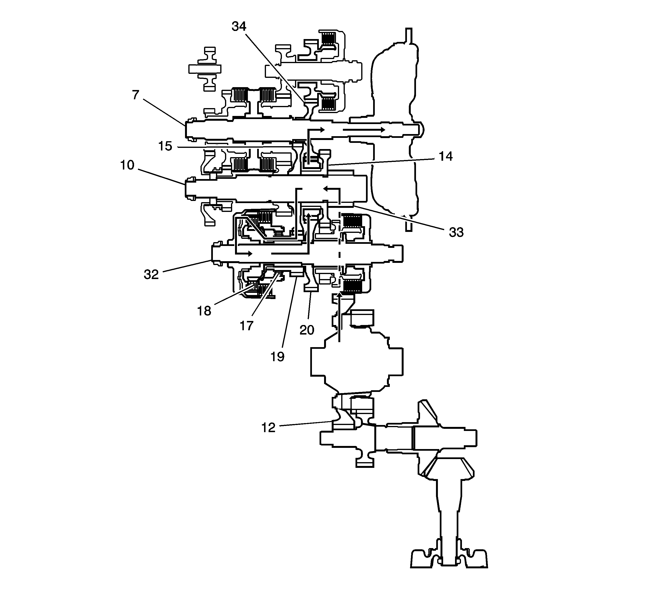
The Power flow when decelerating is as follows:
| • | Hydraulic pressure is applied to the 1st clutch (18) and
the coast/one-way clutch (17). Rolling resistance from the road surface goes
through the front wheels to the final drive gear (33), then to the output shaft
idler gear (14). |
| • | The coast/one-way clutch (17) disengages because the application
of torque is reversed. |
| • | The counterforce conveyed to the 1st/2nd clutch shaft drive gear turns
the mainshaft 3rd gear (34) via the output shaft idler gear (14).
As a result, engine braking can be obtained with 1st gear. |
R Gear Power Flow
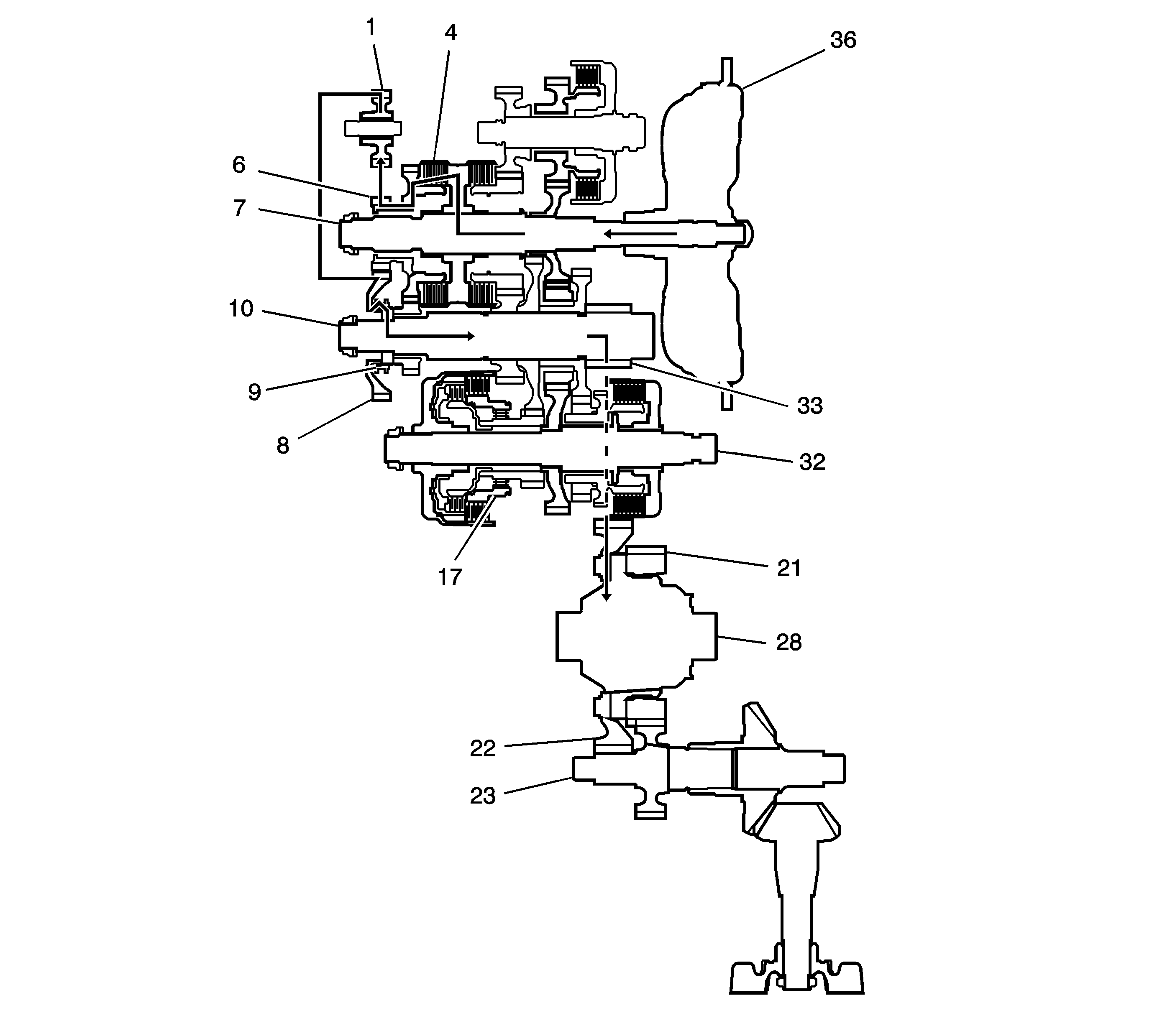
| • | Hydraulic pressure is also applied to the 5th clutch (4),
then the 5th clutch (4) engages the mainshaft reverse gear (6)
with the mainshaft (7). |
| • | The mainshaft reverse gear (6) drives the output shaft reverse
gear (8) via the reverse idler gear (1). |
| • | The rotation direction of the output shaft reverse gear (8) is
changed via the reverse idler gear (1). |
| • | The output shaft reverse gear (8) drives the output shaft (10)
via the reverse selector, which drives the reverse selector hub (9). |
| • | IF AWD, power is transmitted to the final drive gear (33), which
in turn drives the final driven gear (22) and the transfer drive gear (21).
Then the transfer output shaft (23) drives the transfer case hypoid drive gear/shaft
and the transfer output shaft/hypoid gear. |
| • | If FWD, power is transmitted to the final drive gear (33) which
in turn drives the final driven gear (22), which turns the front differential
assembly (28). |


