For 1990-2009 cars only
Tools Required
SA9179NE Dial Indicator
- Measure the axial clearance for the reverse driven gear (512).
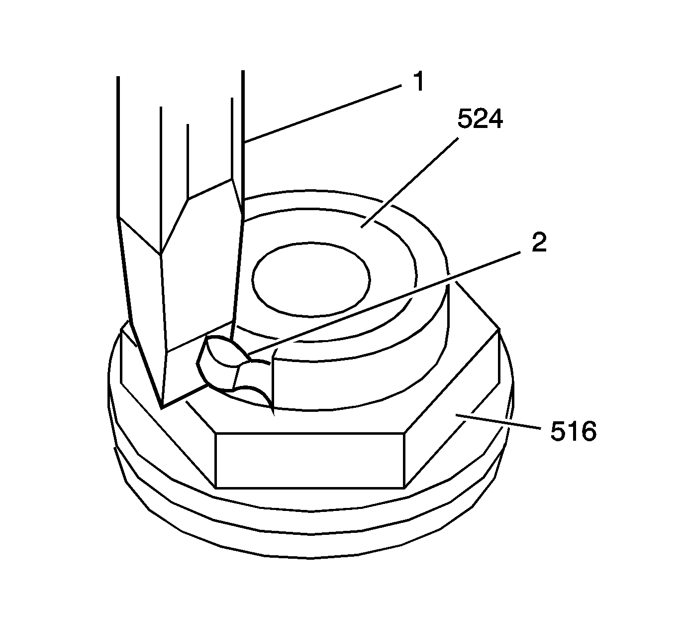
- Using a chisel (1) cut the locktab (2) on the output shaft retaining nut (516). Do not damage the threads on the output shaft (524).
- Remove the output shaft retaining nut (516).
- Remove the output shaft washer (515).
- Using a hydraulic press remove the output shaft rear bearing (514).
- Remove the following components from the output shaft (524):
- Measure the 5th driven gear (507) axial clearance.
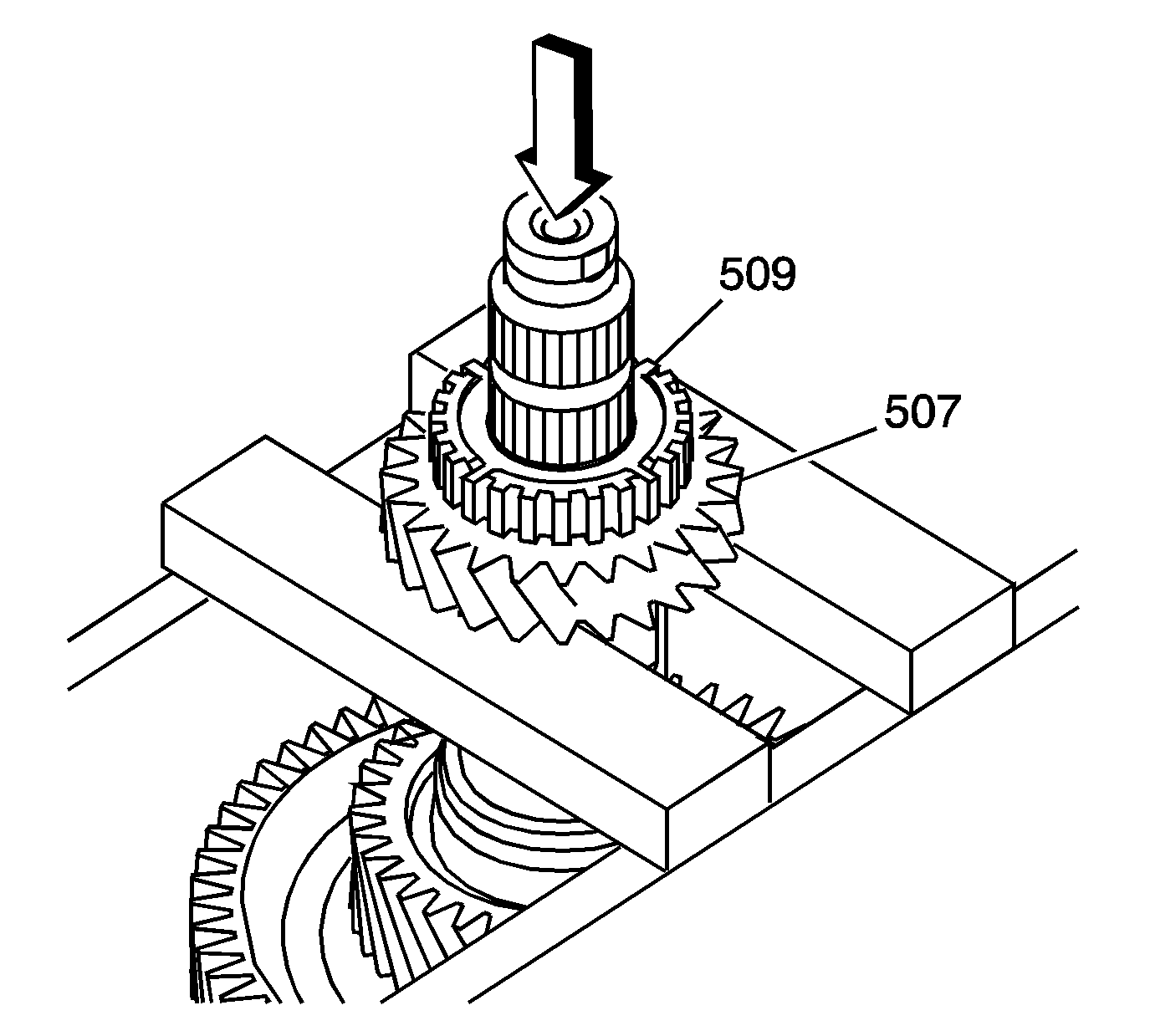
- Using a hydraulic press remove the 5th/reverse synchronizer hub (509) and the 5th driven gear (507).
- Remove the 5th driven gear inner bearing (506).
- Remove the 5th driven gear spacer (505).
- Remove the following components from the output shaft:
- Remove the following components from the output shaft (524):
- Inspect all bearings for wear or damage.
- Inspect the output shaft (524) bearing surfaces and shaft splines for scoring, excessive wear, or damage. Replace the output shaft if faulty.
- Inspect the gear bearing surfaces for excessive wear or damage. Refer to Output Shaft in Transmission Clearance Specifications .
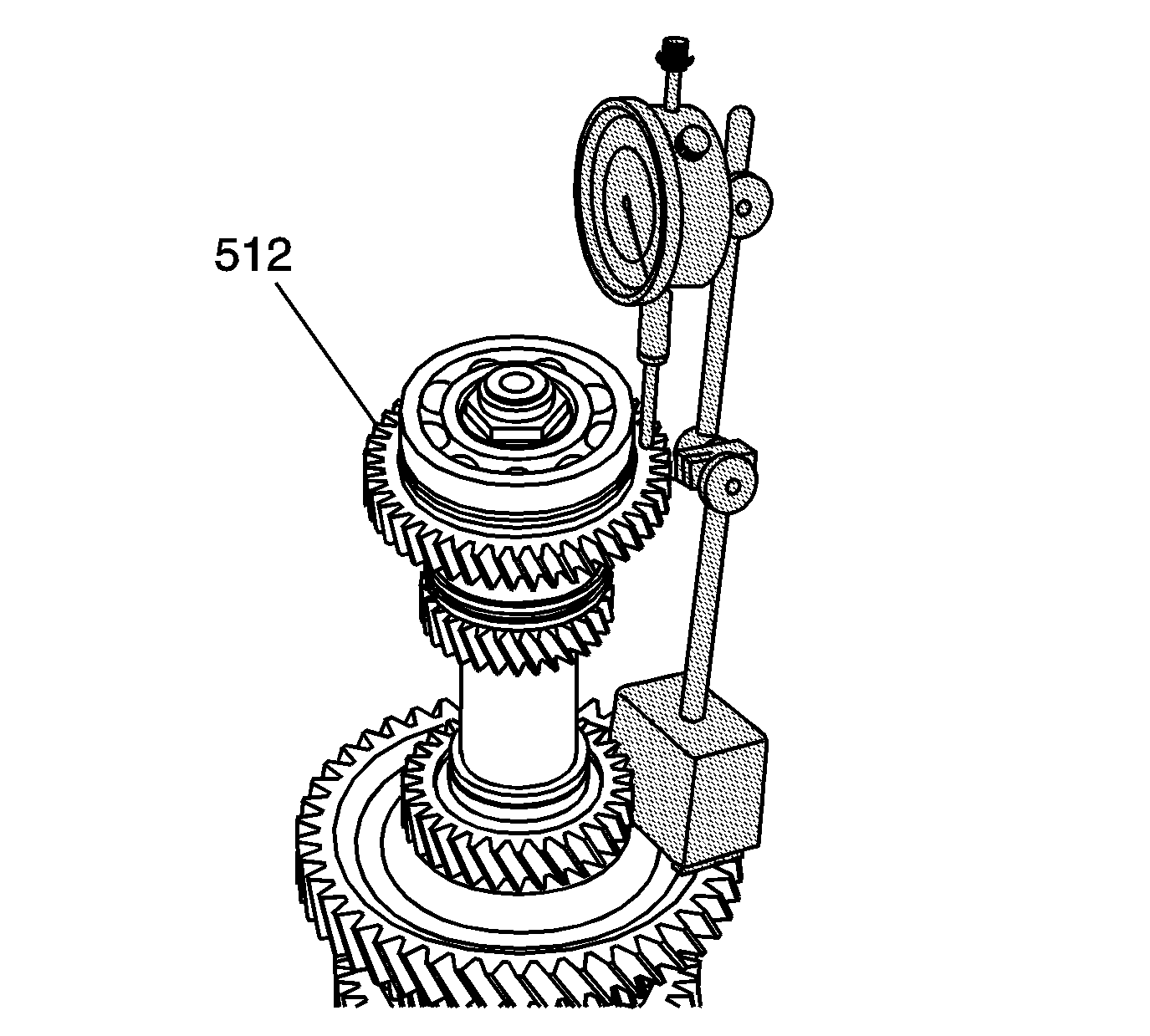
| 1.1. | Install the SA9179NE on the reverse driven gear. |
| 1.2. | Zero the gage. |
| 1.3. | Lift up on the reverse driven gear and record the measurement. |
Specifications
Reversed driven gear axial clearance 0.10-0.25 mm
(0.0039-0.0098 in)
| 1.4. | If the clearance is out of specifications inspect for excessive wear on the thrust surface of the reverse driven gear (512) or the 5th/reverse synchronizer hub (509). |
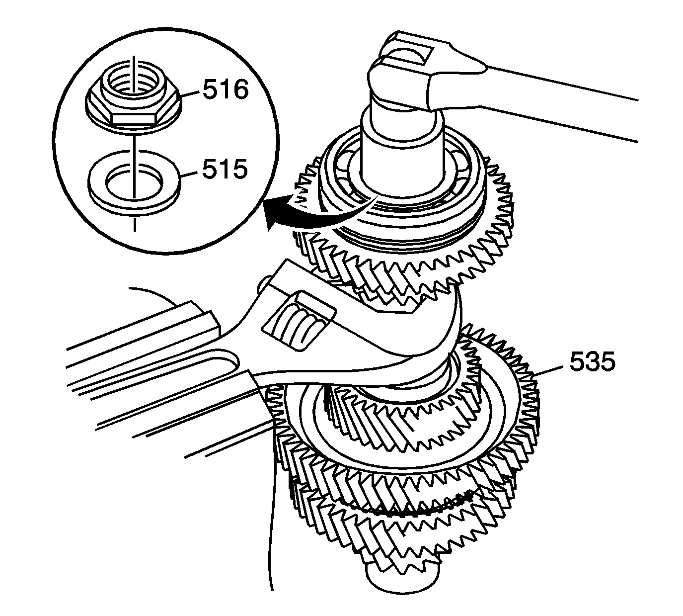
Important: The output shaft retaining nut (516) is left handed thread.
| • | Use an adjustable wrench held in a vise. |
| • | Securely hold the output shaft. |
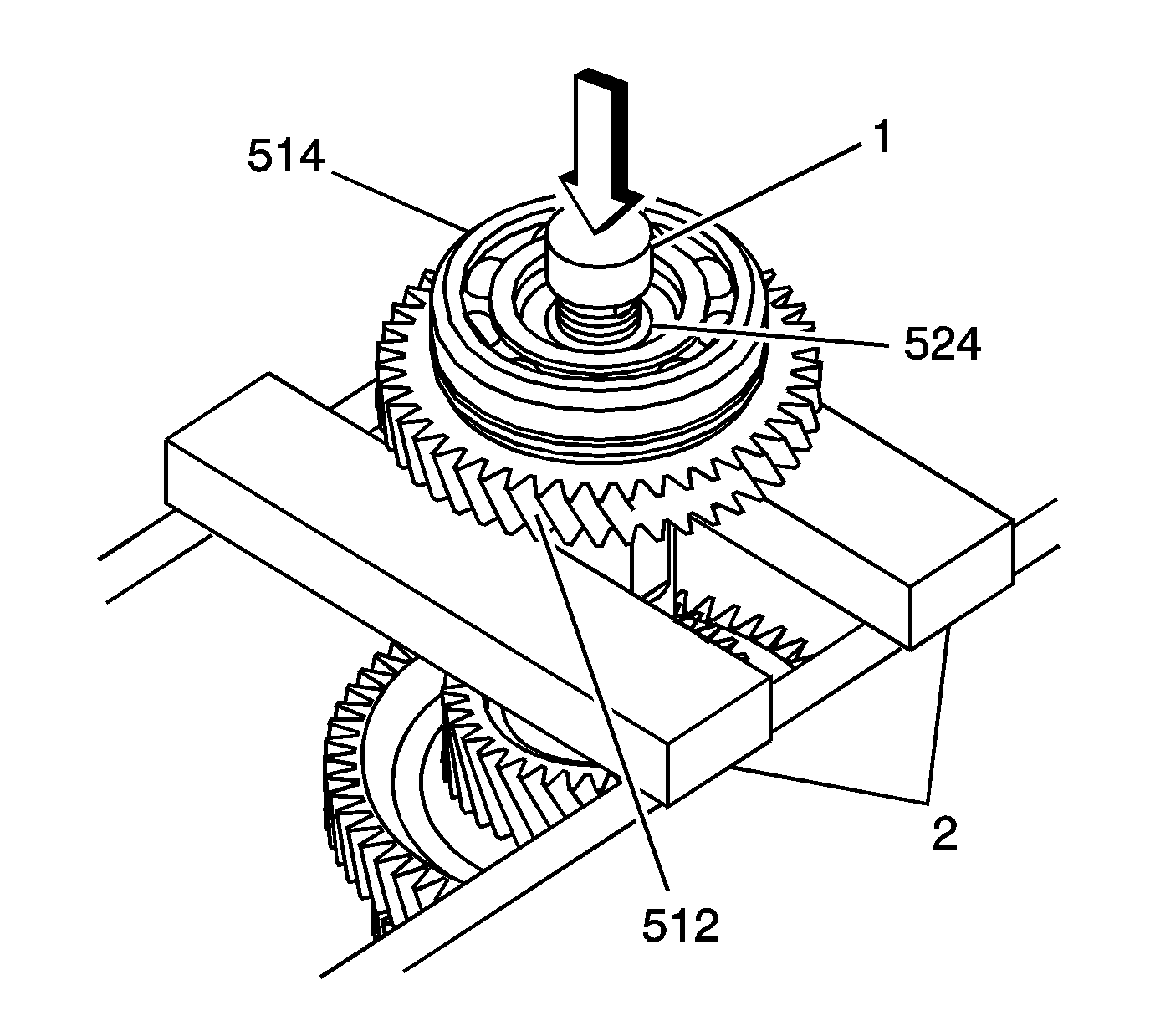
| • | Use press plates (2) under the reverse drive gear (512). |
| • | Use a shaft protector (1) to prevent damage tot he output shaft threads. |
| • | Support the output shaft (524) to prevent the shaft from dropping. |
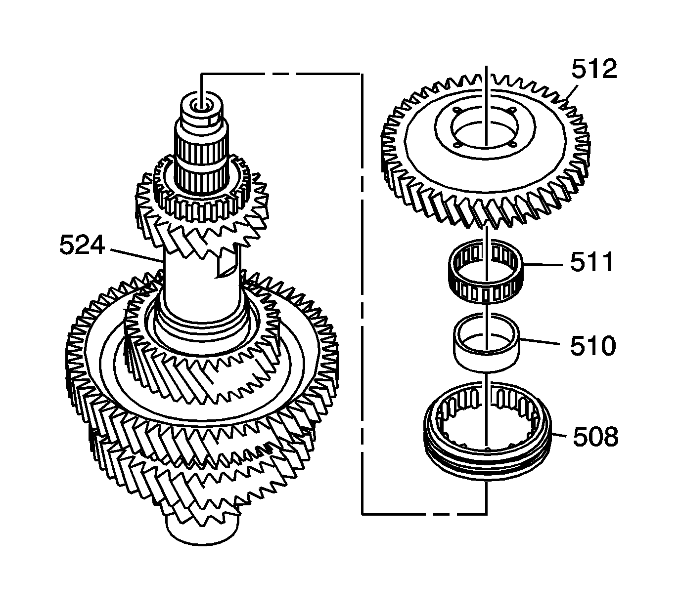
| • | The reverse driven gear (512) |
| • | The reverse driven gear inner bearing (511) |
| • | The reverse driven gear inner bearing race (510) |
| • | The reverse synchronizer sleeve (508) |
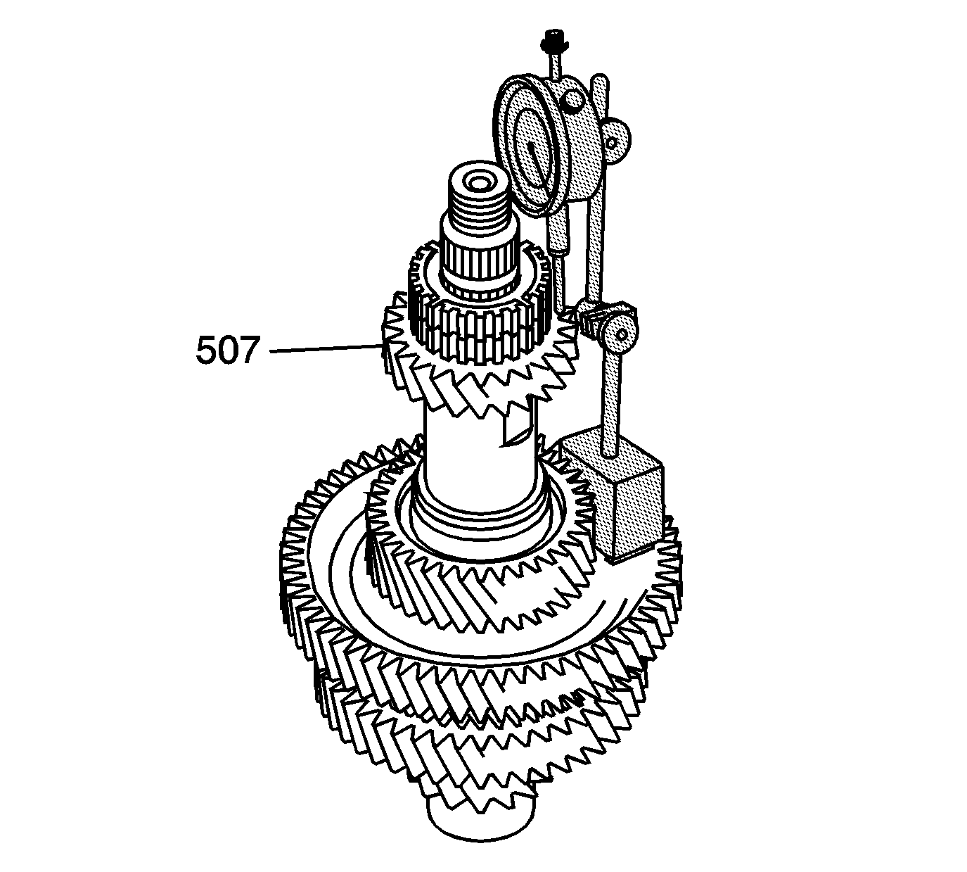
| 7.1. | Install the SA9179NE on the 5th driven gear. |
| 7.2. | Zero the gage. |
| 7.3. | Lift up on the 5th driven gear and record the measurement. |
Specifications
5th driven gear axial clearance 0.12-0.27 mm
(0.0047-0.0106 in)
| 7.4. | If the clearance is out of specifications inspect for excessive wear on the thrust surface of the 5th driven gear (507), the 5th/reverse synchronizer hub (509), and the shoulder of the output shaft (524). |
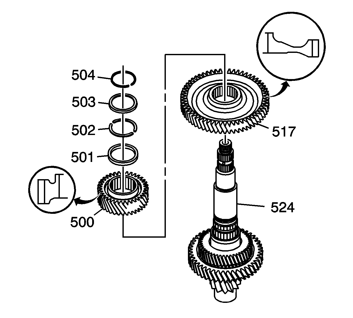
| • | The 3rd/4th driven gear retaining ring cap retainer (504) |
| • | The 3rd/4th driven gear retaining ring cap (503) |
| • | The 3rd/4th driven gear retaining rings (502) |
| • | The 3rd/4th driven gear selective spacer (501) |
| • | The 3rd/4th driven gear (500) |
| • | The 1st driven gear (517) |
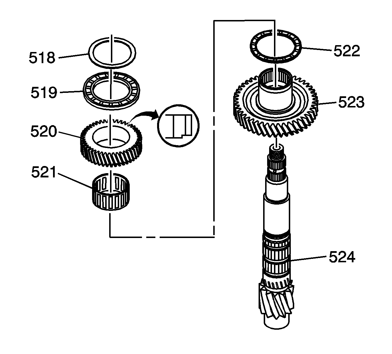
| • | The 1st driven gear selective spacer (518) |
| • | The 1st/2nd idler gear thrust bearing (519) |
| • | The 1st/2nd idler gear (520) |
| • | The 1st/2nd idler gear inner bearing (521) |
| • | The 1st/2nd driven gear thrust bearing (522) |
| • | The 1st/2nd driven gear (523) |
