Tools Required
Note these items during assembly:
| • | Apply automatic transmission fluid to all O-ring seals before assembly. |
| • | Soak all clutch fiber plates thoroughly in automatic transmission fluid for a minimum of 30 minutes. |
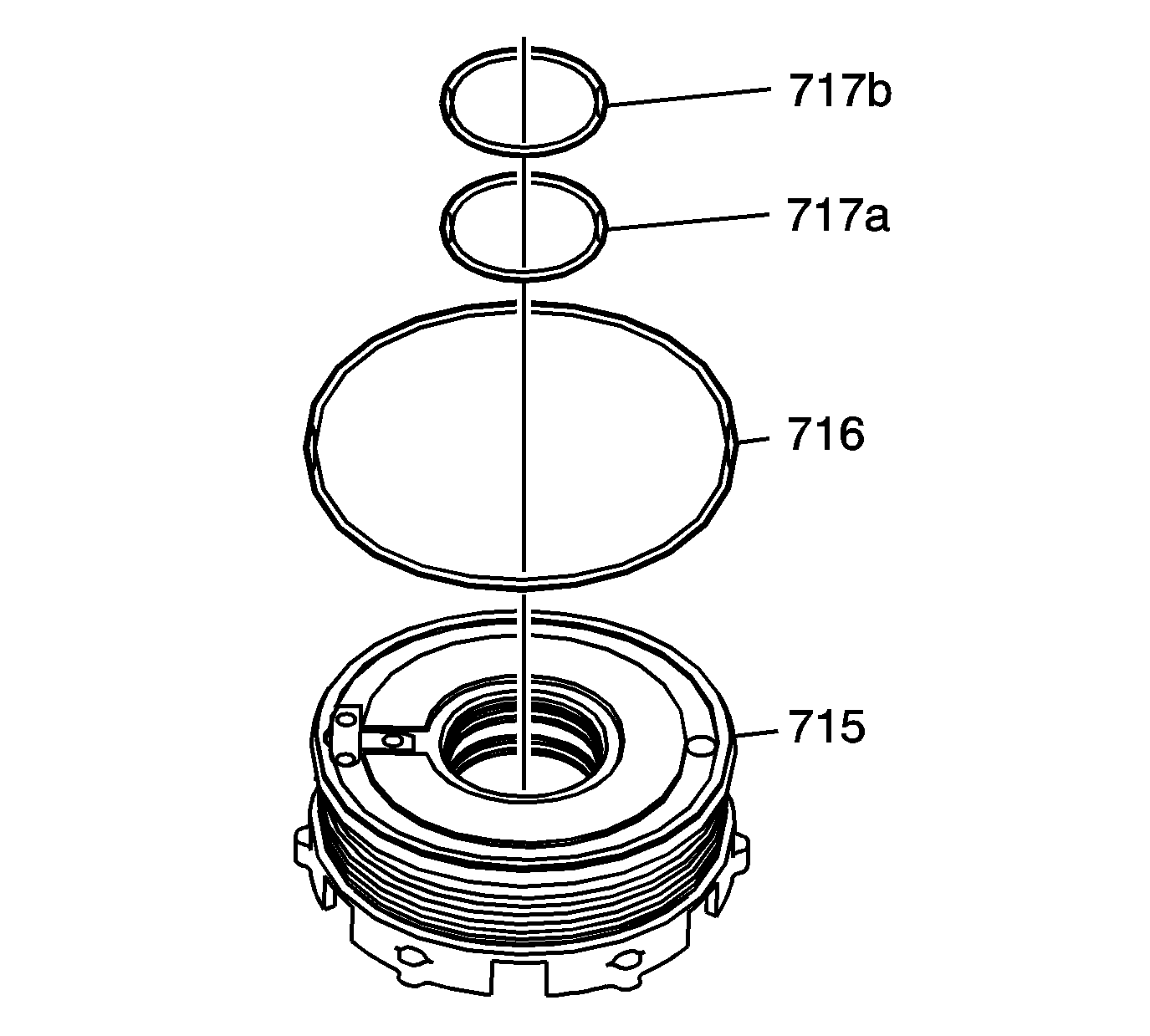
- Install inner O-ring seals in the 1st clutch piston (715) as follows:
| • | Upper, forward inner groove, O-ring seal (717a) |
| • | Lower, rear inner groove, O-ring seal (717b) |
- Install an outer O-ring seal (716) in the outer groove of the 1st clutch piston (715).
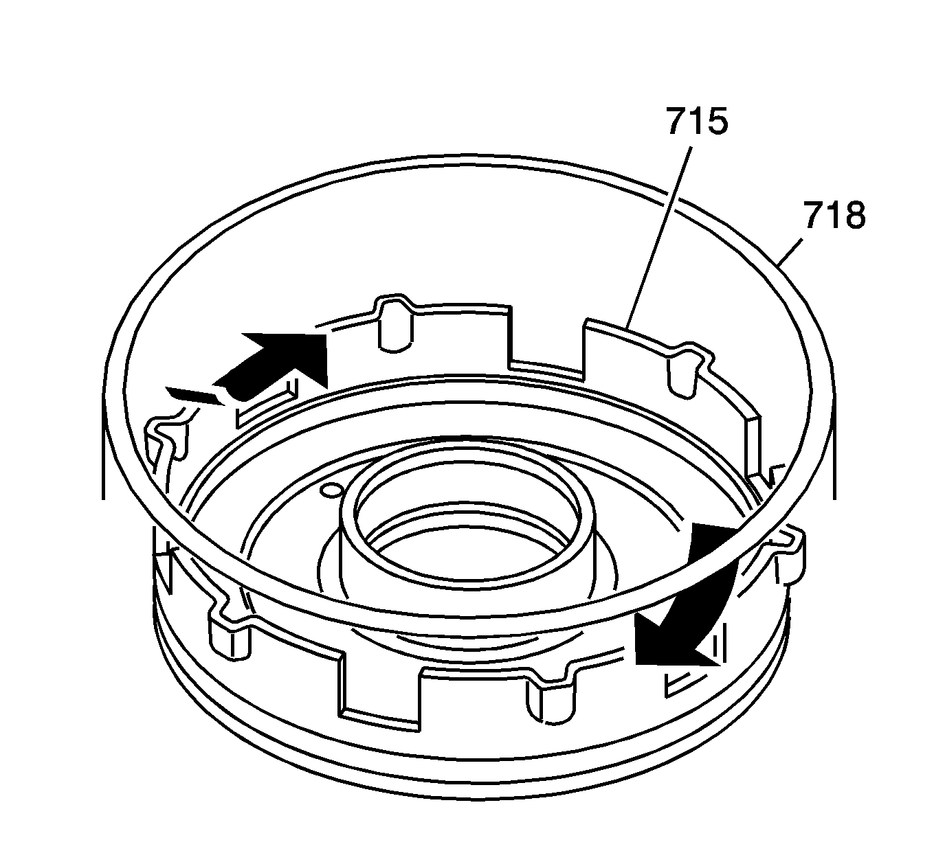
- Install the 1st clutch piston (715) into the 1st and coast clutch housing (718) by applying
hand pressure and rotating the 1st clutch piston assembly.
| • | Ensure proper O-ring seating. |
| • | Do not pinch the O-ring seal by installing the piston with excessive force. |
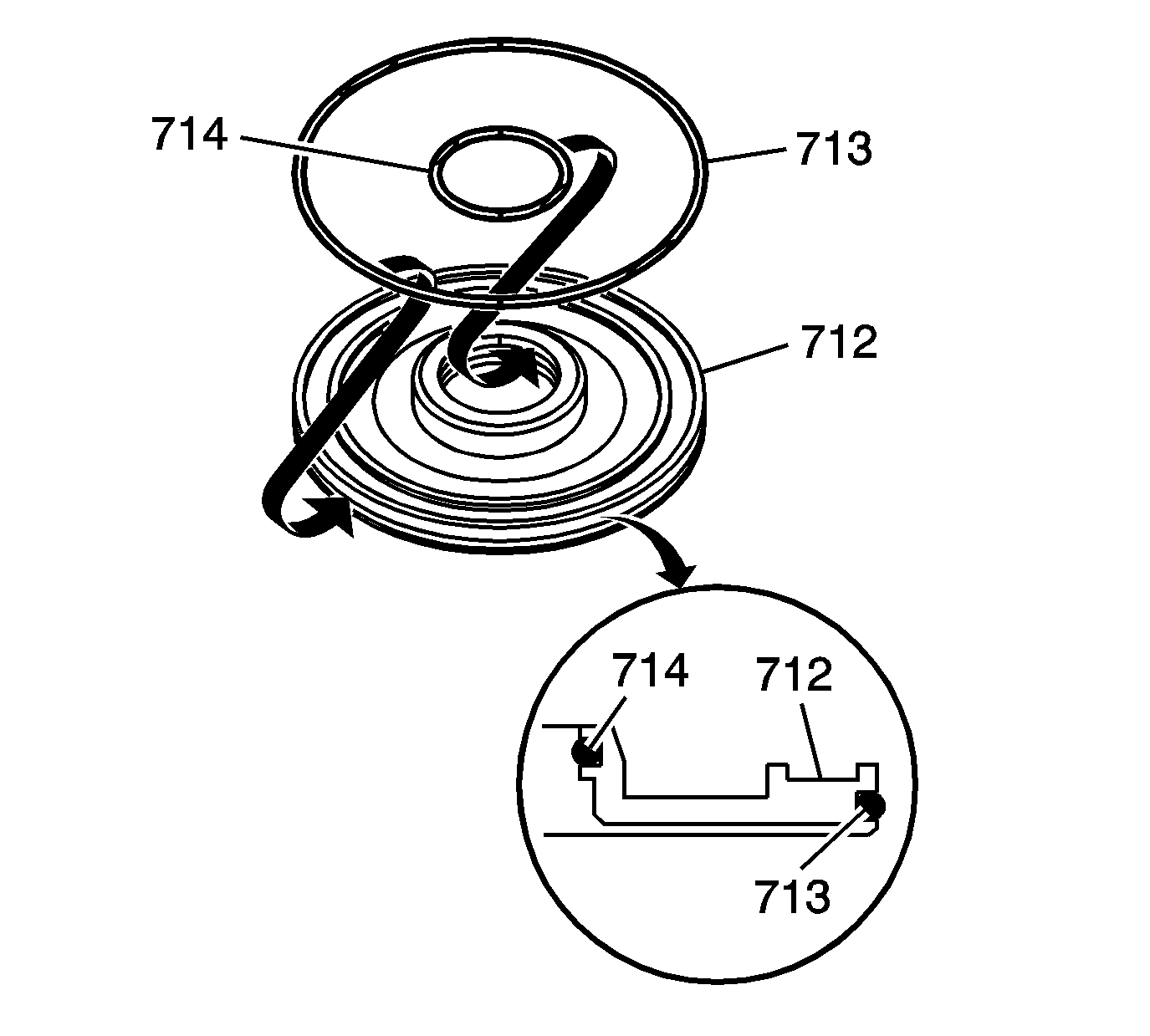
- Install O-ring seals in the coast clutch piston (712) as follows:
| • | Inner groove, inner coast clutch O-ring seal (714) |
| • | Outer groove, outer coast clutch O-ring seal (713) |
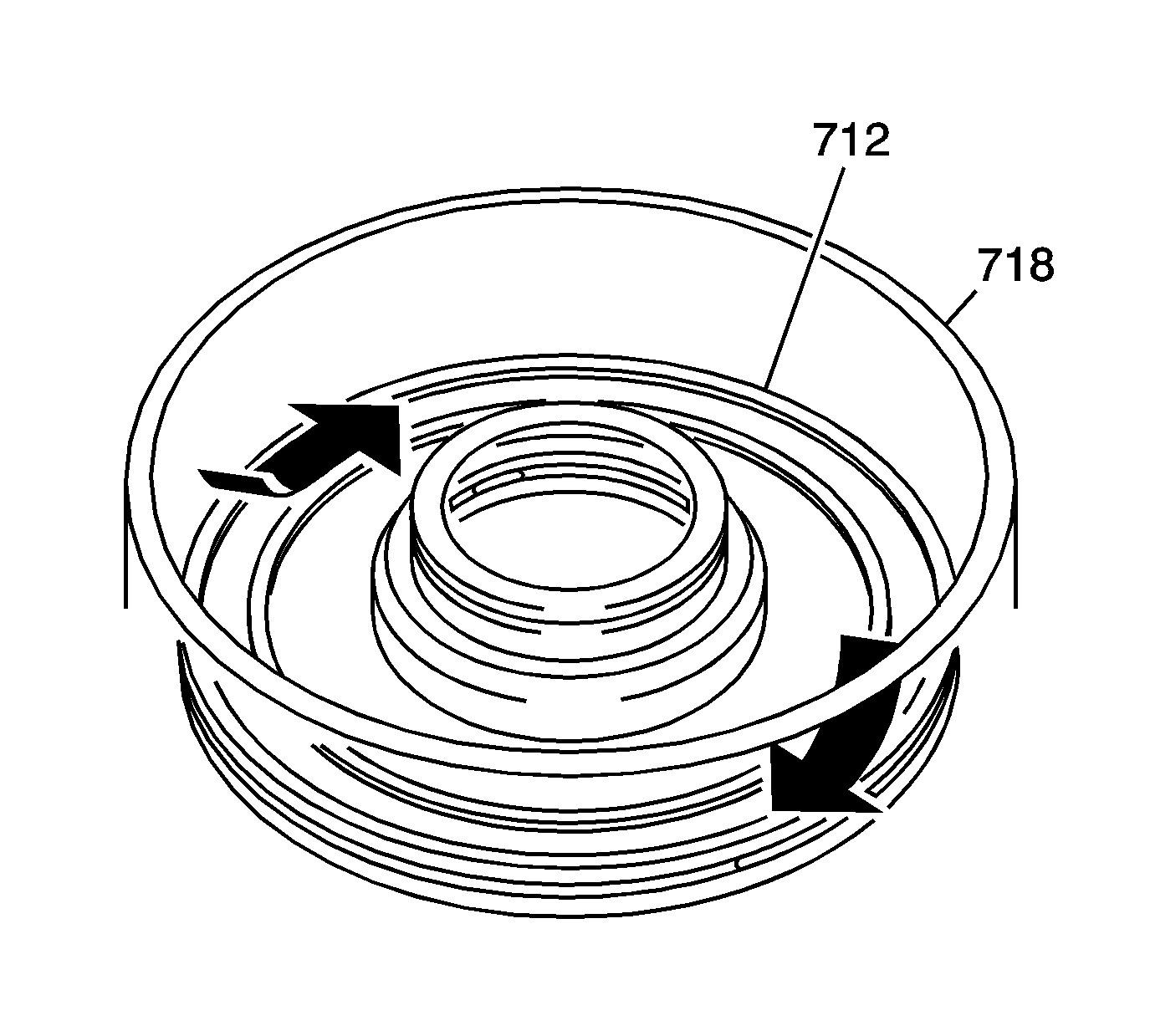
- Install the coast clutch piston (712) into the 1st and coast clutch housing (718) by applying
hand pressure and rotating the coast clutch piston assembly.
| • | Ensure proper O-ring seating. |
| • | Do not pinch the O-ring seal by installing the piston with excessive force. |
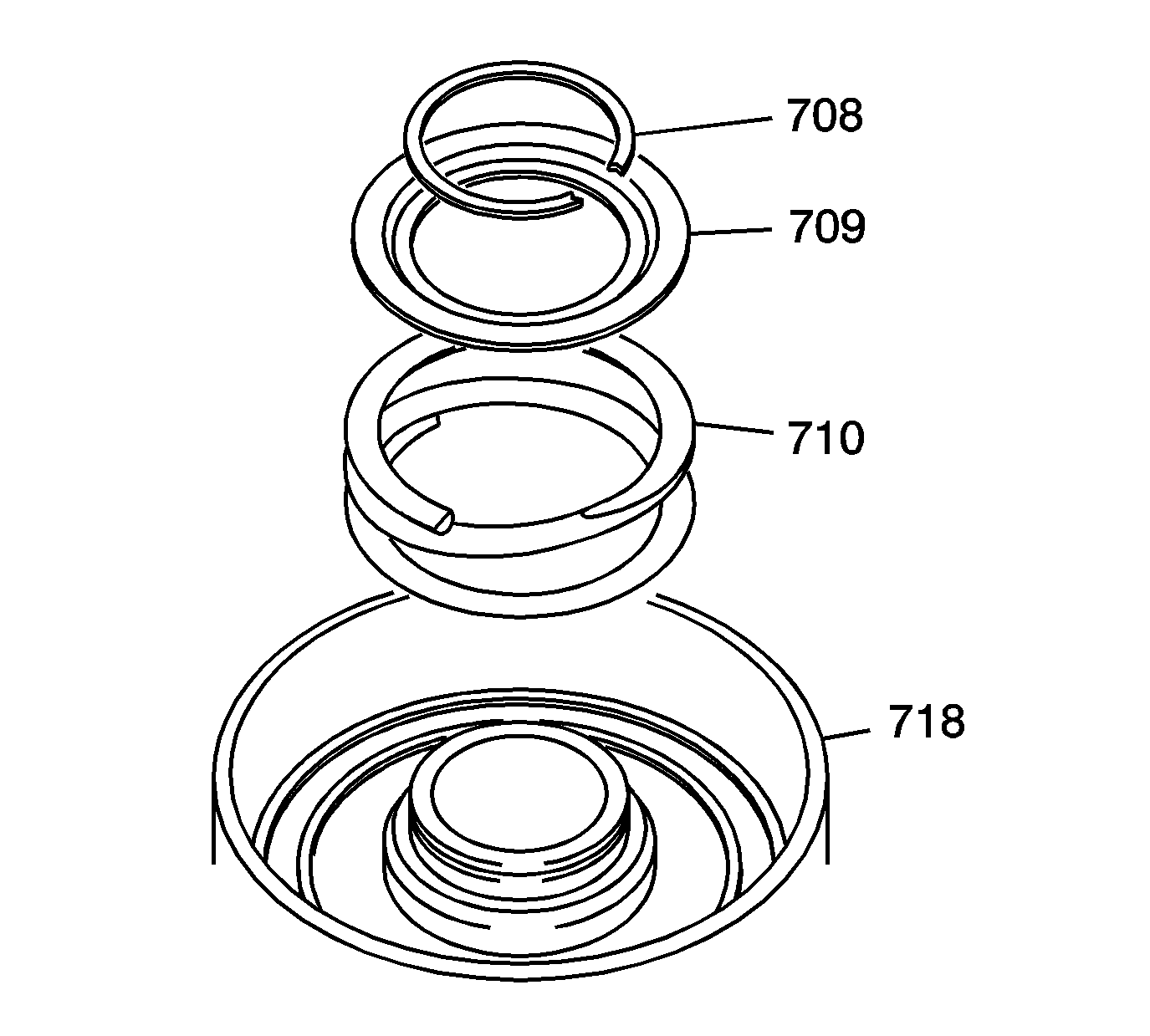
- Install the following components into the 1st and coast clutch housing (718):
| • | 1st and coast clutch piston return spring (710) |
| • | 1st and coast clutch piston return spring retainer cap (709) |
| • | 1st and coast clutch piston return spring retainer cap 44 mm retaining ring (708) on the retainer cap |
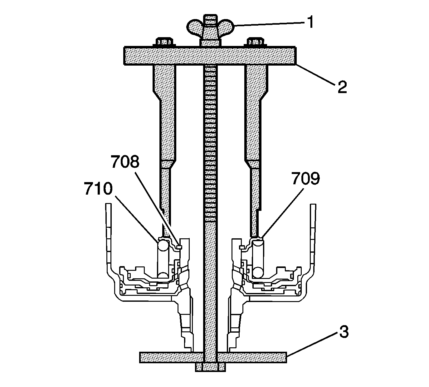
Important: Position the legs of the
J 45124
on the spring retainer cap only where the spring is in contact with the cap.
- Using the bridge and legs of the
J 45124
(2) with the forcing screw of the
J 23327
(1) and J 21420-2 (3) plate
of the
J 23327
, compress the clutch piston return spring (710) until the groove for the clutch spring retainer cap retaining ring (708) is accessible.
| • | Adjust the legs of the
J 45124
to have full contact with the clutch piston return spring retainer cap (709). |
| • | Ensure the legs remain in position where the spring retainer cap is in contact with the spring. |
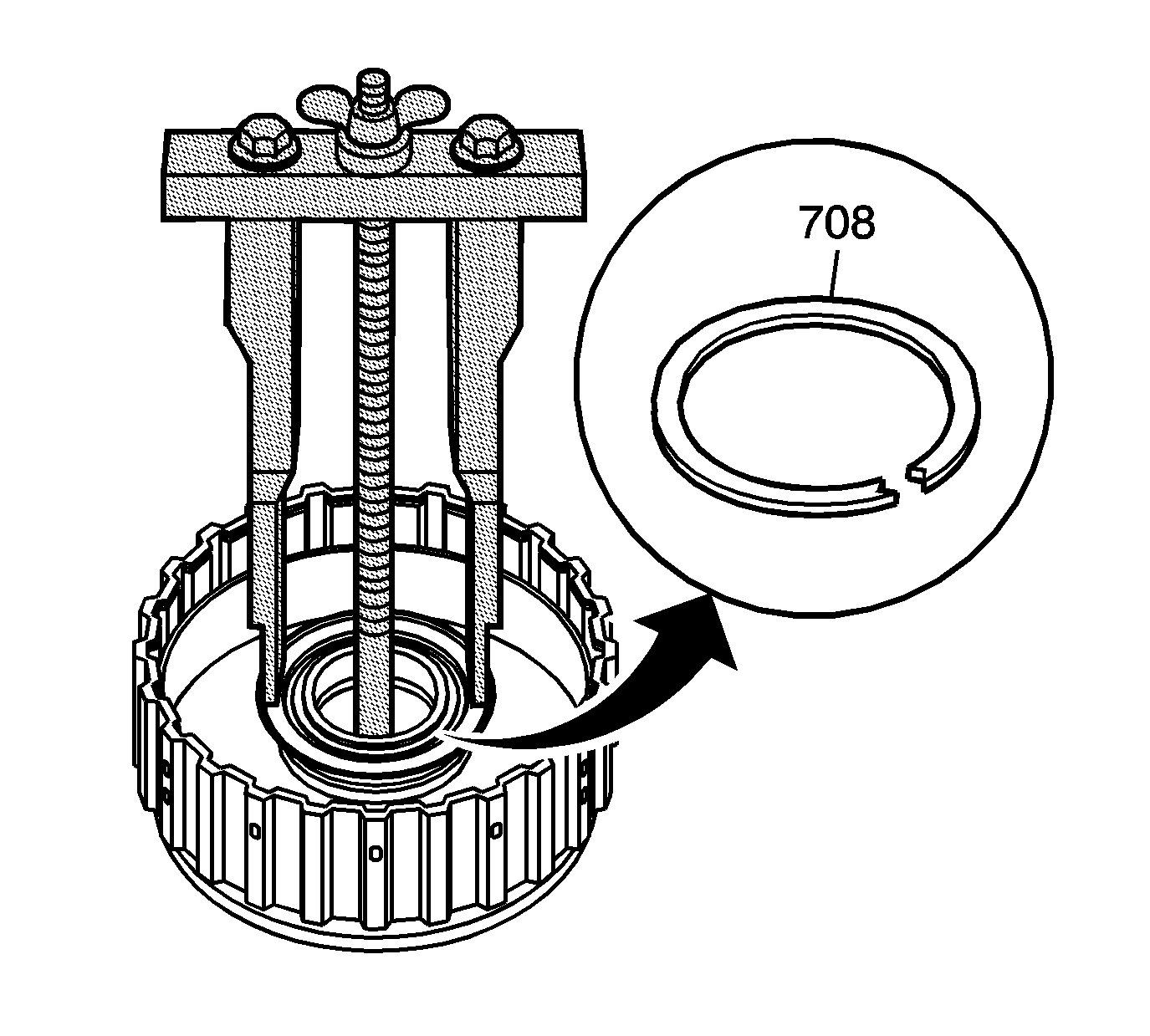
- Install the 44 mm 1st and coast clutch return spring retaining cap retaining ring (708).
- Remove the tools.
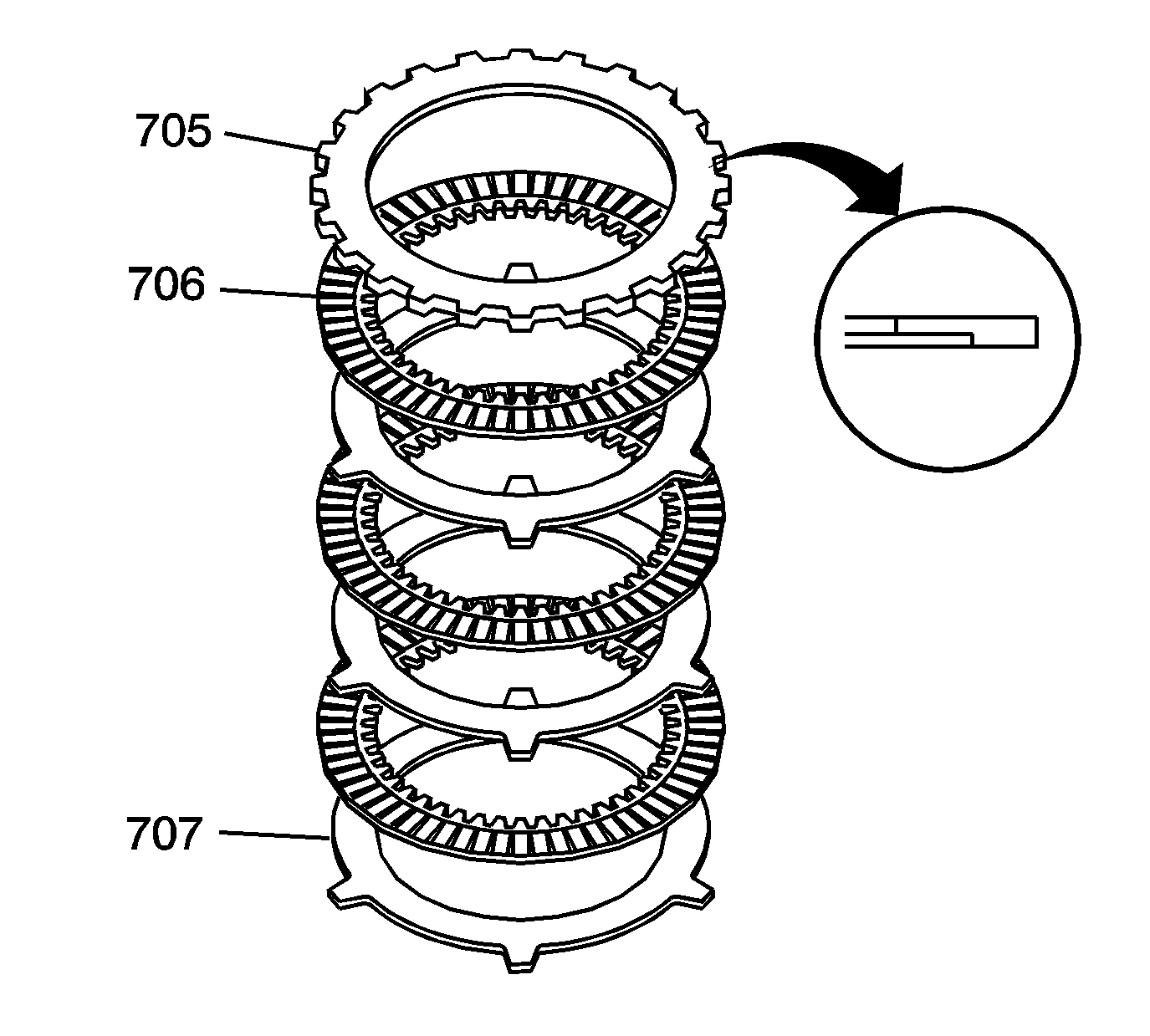
- Install into the 1st and coast clutch housing (718) the following components:
| • | Coast clutch steel plate (707) |
| • | Coast clutch fiber plate (706) |
| • | Continue to alternately install the above components until a total of 3 each have been installed. |
| • | Selective coast clutch backing plate (705) in the direction shown |
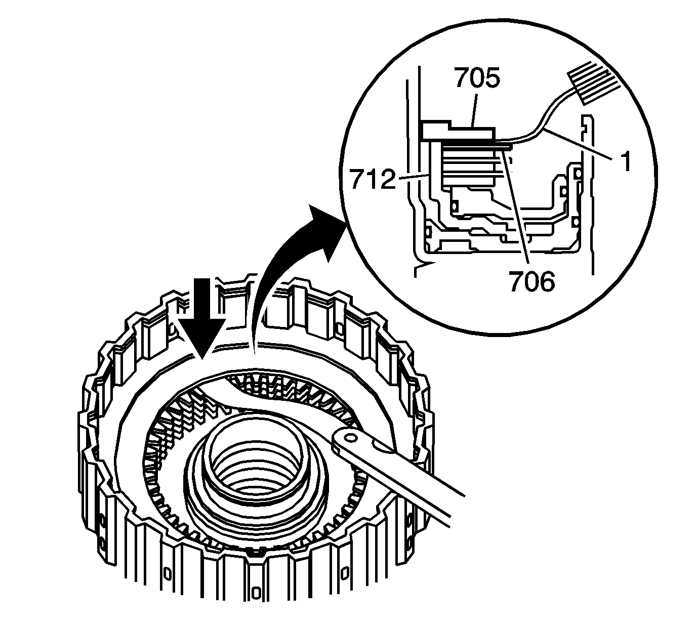
- By hand, press down on the coast clutch backing plate (705) in order to seat the backing plate to the
coast clutch piston (712).
- Measure the coast clutch clearance between the coast clutch backing plate (705) and the top coast clutch fiber plate (706) with a feeler gage (1).
| • | Measure in at least 3 places. |
| • | Use the average of the 3 measurements as the actual clearance. |
Specification
0.6-1.0 mm (0.024-0.039 in)
- If the coast clutch backing plate clearance is out of specification, replace the coast clutch steel (707) and fiber plates (706) as a set, and recheck for proper clearance.
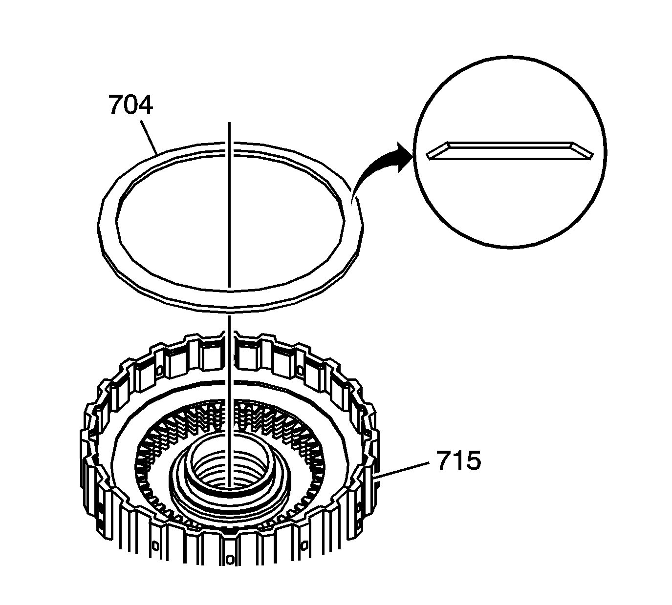
- Install the 1st clutch spring plate (704) in the groove located in the 1st clutch piston (715)
with the cone side facing up.
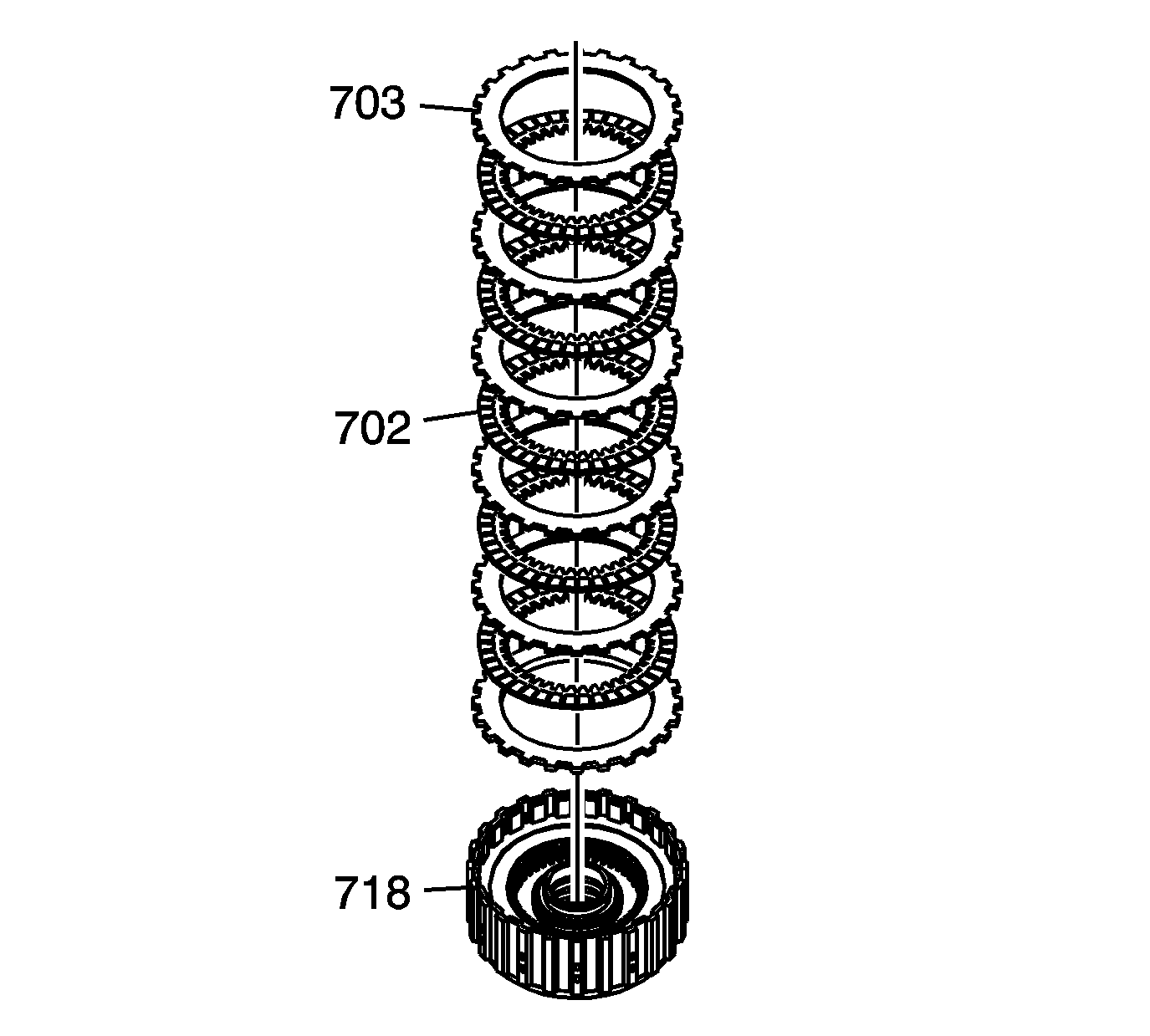
- Install a 1st clutch steel plate (703).
- Instal a 1st clutch fiber plates (702).
- Alternately install the plates until a total of 5 plates each are installed into the 1st clutch housing (718).
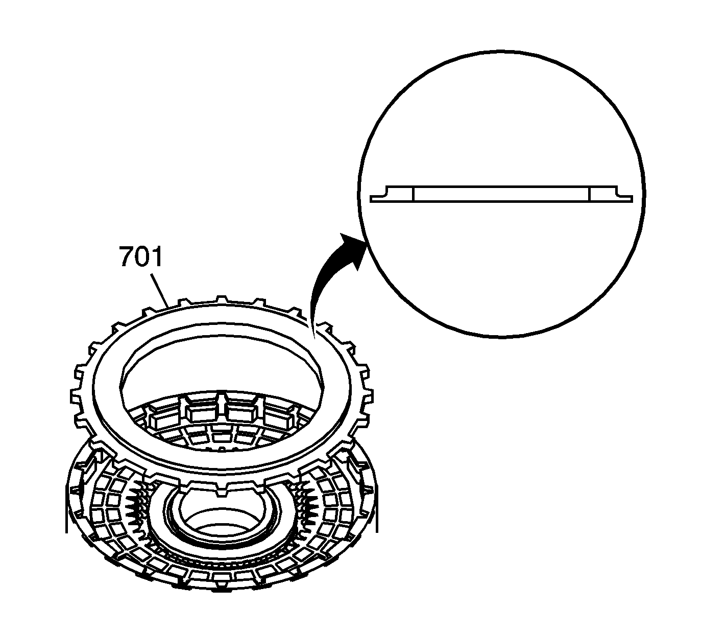
- Install the selective 1st clutch backing plate (701) with the flat side
facing the last 1st clutch fiber plate as shown in the insert.
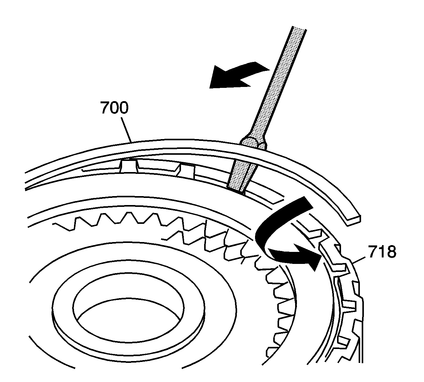
- Using
J 28585
, install the 141 mm 1st clutch backing plate retaining
ring (700).
Ensure that the retaining ring is fully seated in the groove of the 1st and coast clutch housing (718).
- Measure the clutch backing plate clearance. Refer to
Clutch Backing Plate Clearance Measurement
.


