For 1990-2009 cars only
Tools Required
| • | DT 46429 Oil Seal Driver |
| • | DT 46512 Seal Installer |
| • | EN 46342 Driver Handle |
| • | J 44873 Pinion Flange Holder and Remover |
- Lubricate all internal components with GM P/N 12578261 (Canadian P/N 10953455) prior to assembly.
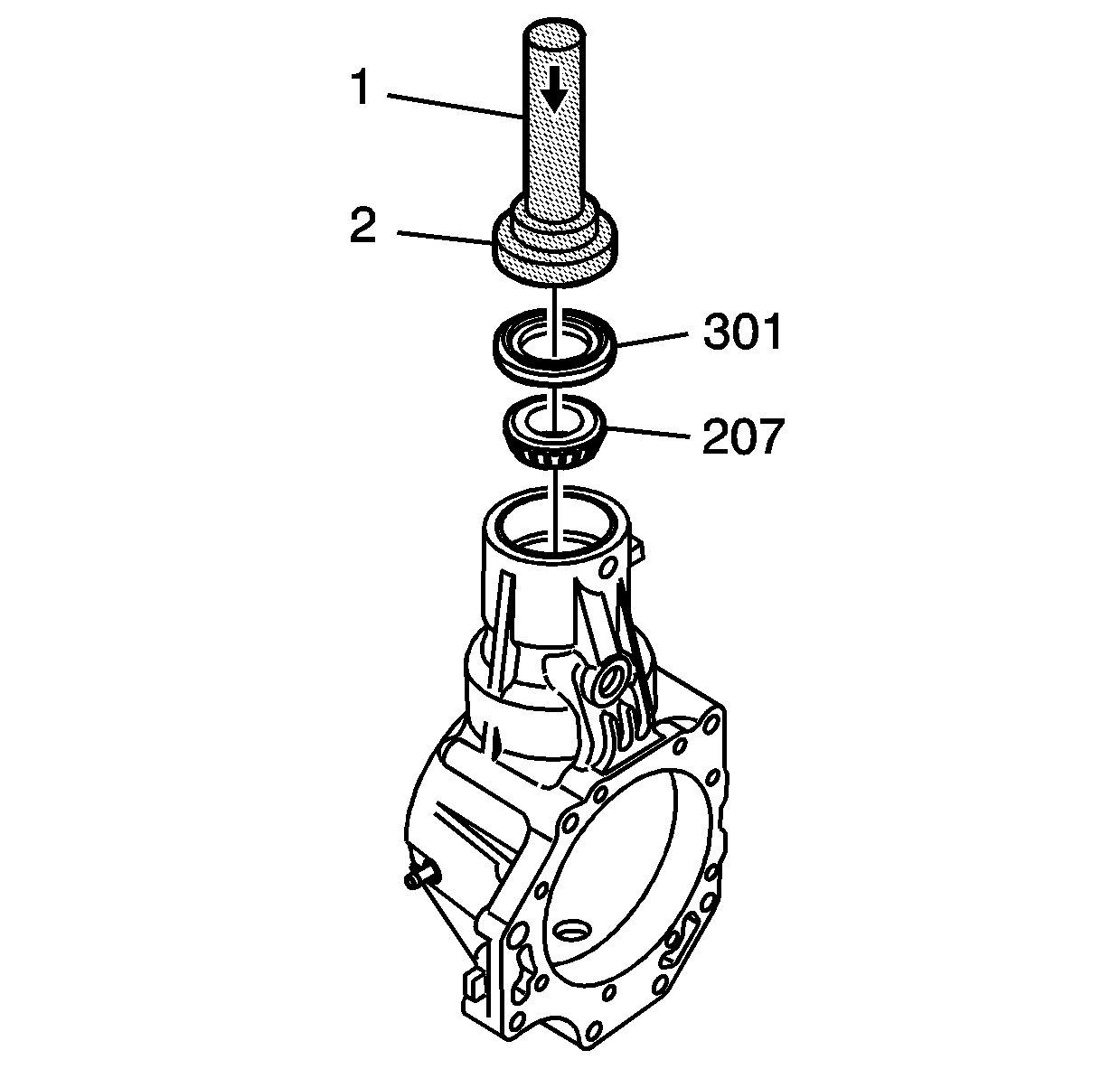
- Use the EN 46342 (1) and the DT 46429 (2) in order to install the bearing (207) and seal (301).
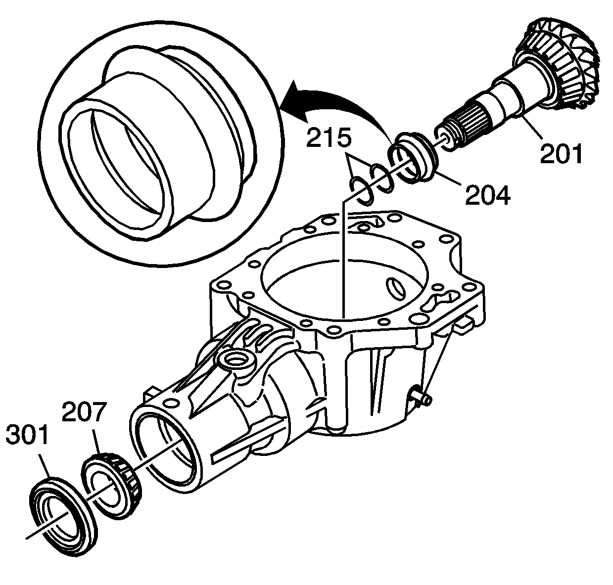
- Install the output shaft (201) with bearing, NEW collapsible spacer (204) and washers (215). Note the proper installation direction of the spacer (204).
- Lubricate the threads of the output shaft with GM P/N 12378261 (Canadian P/N 10953455).
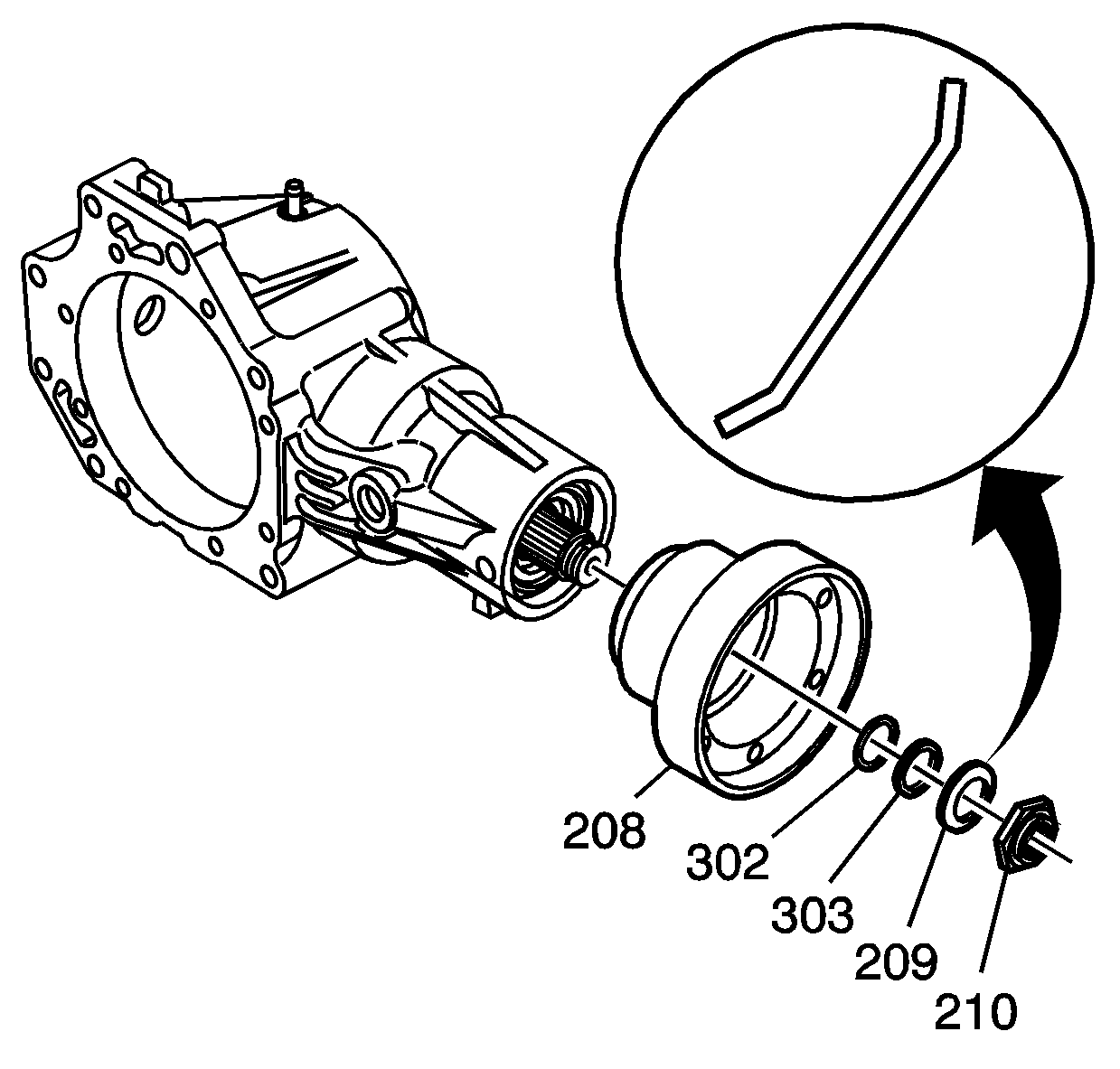
- Install the output yoke (208), NEW O-ring (302), NEW sealing washer (303), NEW washer (209), and NEW locknut (210).
- Secure the case in a soft-jaw vise.
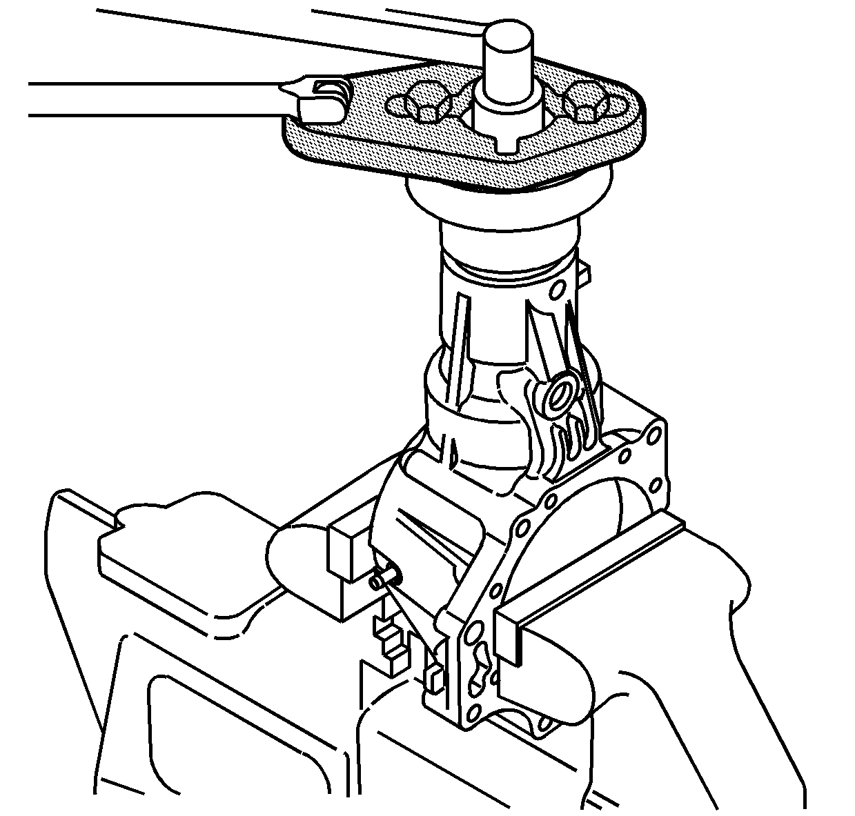
- Install the J 44873 and bolts.
- Tighten the locknut to 108-294 N·m (75.6-217 lb ft) while measuring the rotating torque. Tighten the nut to achieve a rotating torque of 1.15-1.71 N·m (10.2-15.1 lb in).
- Remove the J 44873 and bolts.
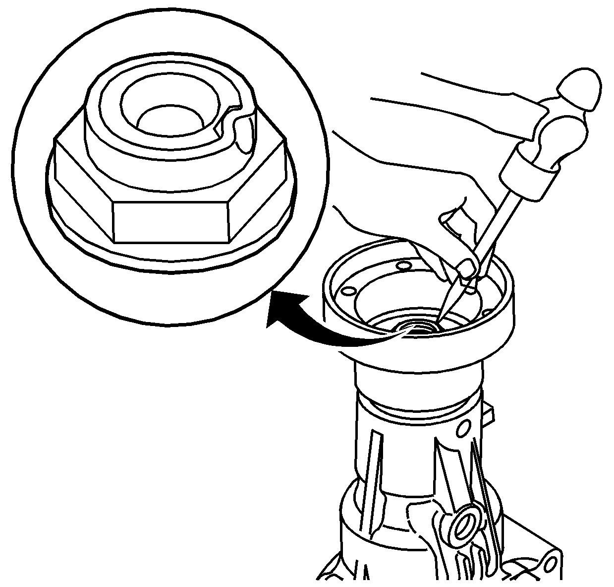
- Stake the locknut using a 3.5 mm (0.138 in) punch.
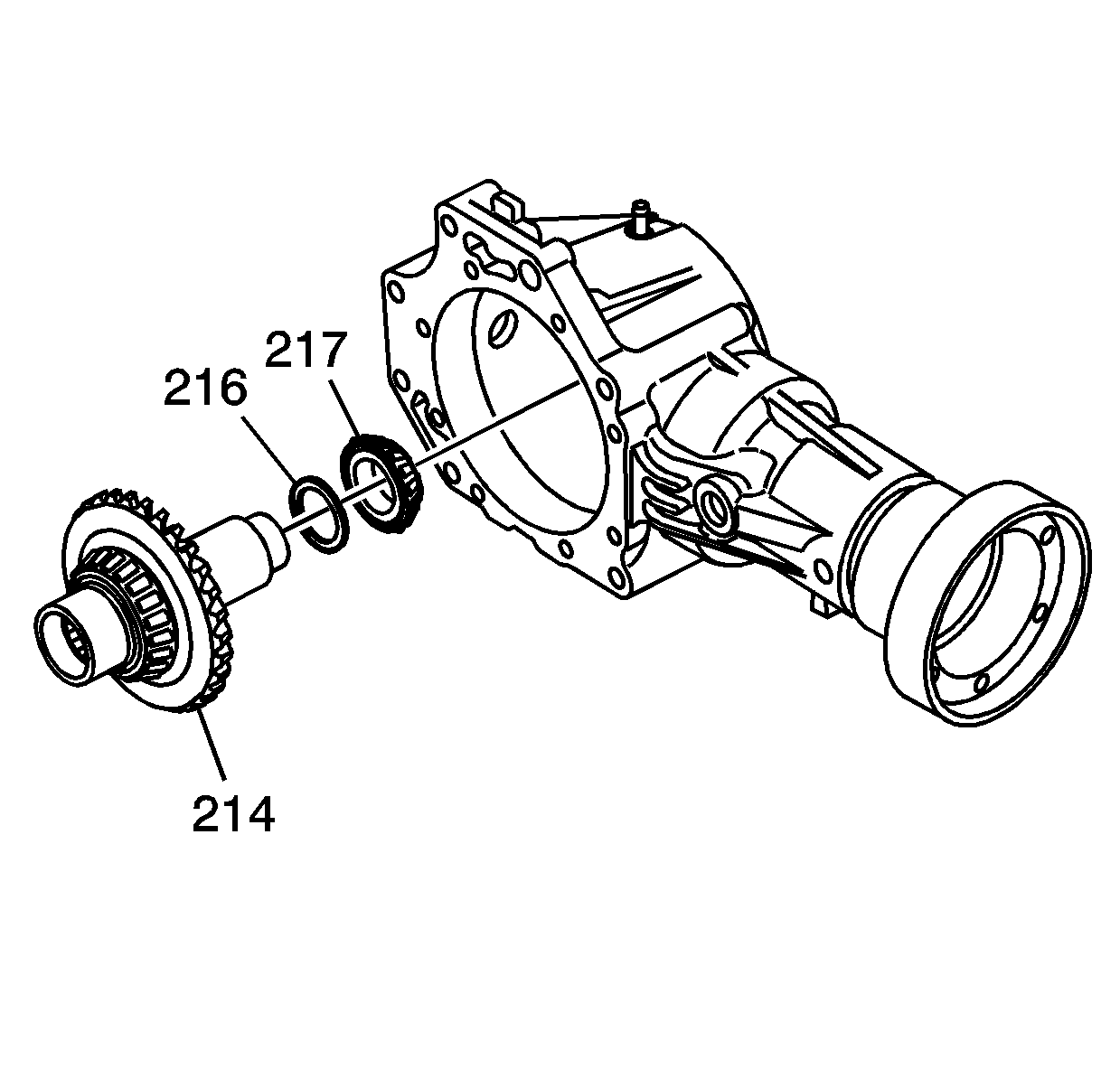
- Install the input gear (214) with shim (216) and bearing (217) into the case.
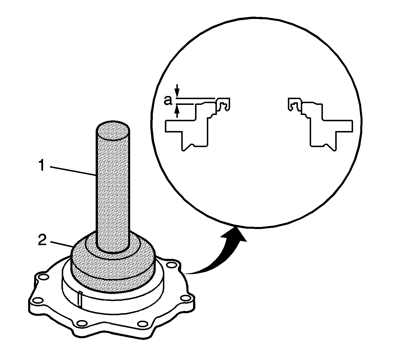
- Using the EN 46342 (1) and the DT 46512 (2), install the oil seal into the cover. Install the seal until the flat surface of the seal measures 0.00-1.0 mm (0.00-0.04 in) flush with or slightly above the surface of the cover (a).
- Install a NEW O-ring (304) to the cover.
- Install the cover (101) and bolts (102).
- Install the locating pin (105).
- Install the fill plug (401) and NEW washer (402).
- Install the drain plug (403) and NEW washer (404).
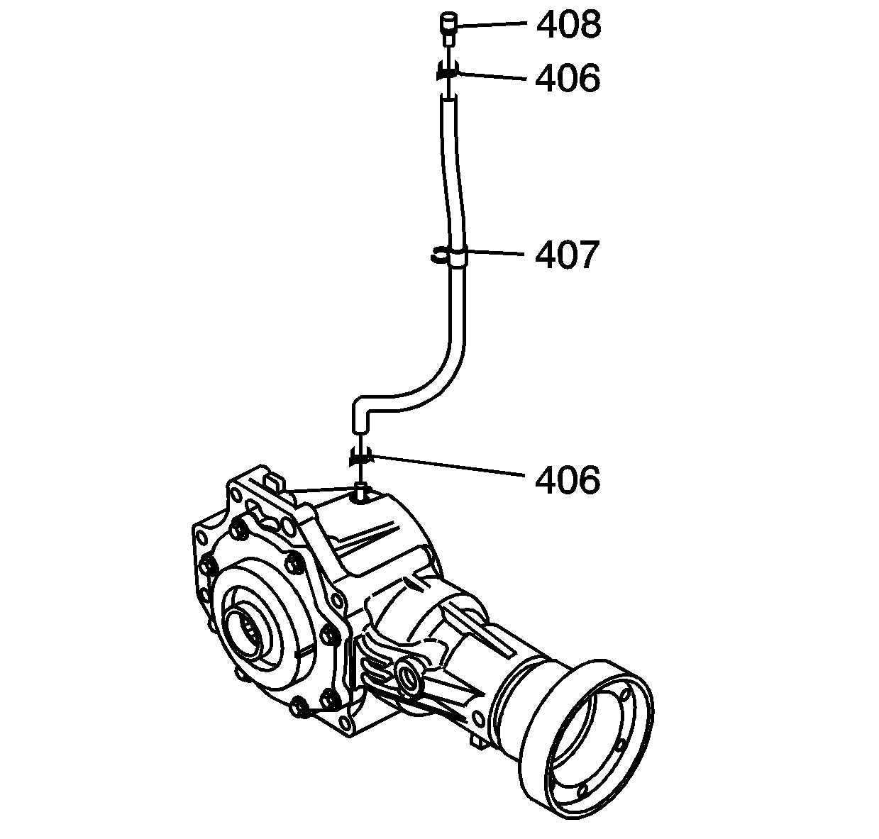
- Install the ventilation valve (408), hose (407), and clamps (406).
- Inspect the unit for proper assembly. Refer to Transfer Case Assembly Inspection .
Notice: Refer to Fastener Notice in the Preface section.
Tighten
Tighten the bolts to 48 N·m (35 lb ft).
Important: Rotate the output yoke several times in both directions to seat the tapered roller bearings prior to measuring the rotating torque.
| • | If the rotating torque exceeds 1.71 N·m (15.1 lb in), replace the collapsible spacer and assemble again. |
| • | If the locknut tightening torque exceeds 294 N·m (217 lb ft), replace the collapsible spacer and assemble again. |
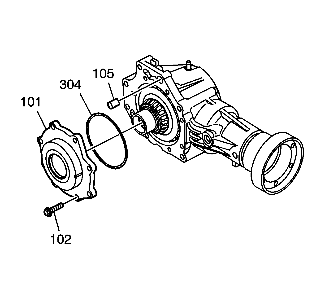
Tighten
Tighten the bolts to 26 N·m (20 lb ft).
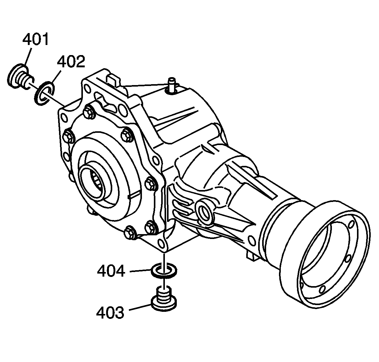
Tighten
Tighten the drain plug to 44 N·m (33 lb ft).
