Tools Required
| • | J 29369-2 Bushing and Bearing Remover - 2-3 Inch |
| • | J 38868 Output Shaft Assembly Remover and Installer |
| • | J 4972-4 Output Shaft Needle Bearing Installer |
| • | J 6125-1B Slide Hammer with Adapter |
Removal Procedure
- Raise and support the vehicle. Refer to Lifting and Jacking the Vehicle .
- Drain the transfer case fluid. Refer to Transfer Case Fluid Replacement .
- Remove the right wheel drive shaft. Refer to Front Wheel Drive Shaft Replacement .
- Remove the intermediate shaft. Refer to Intermediate Shaft Replacement .
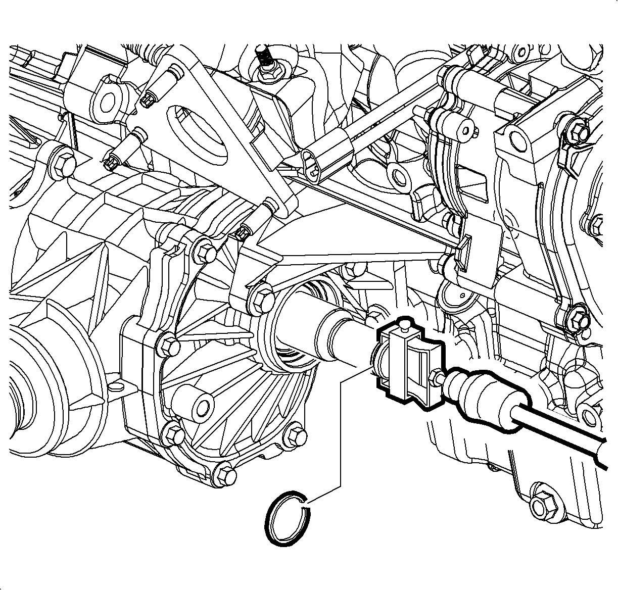
- Remove the retainer ring from the stub shaft for tool installation. Discard the used retainer ring.
- Remove the stub shaft using the J 6125-1B and J 38868 .
- Remove the transfer case mounting bracket. Refer to Transfer Case Bracket Replacement .
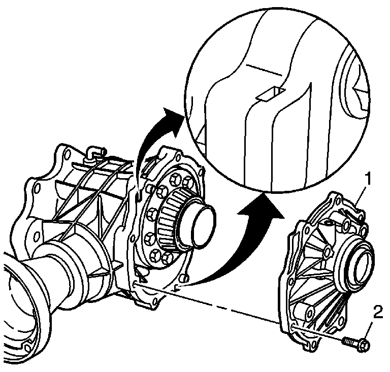
- Remove all bolts (2) from the side cover (1).
- Use the pry point relief slots to remove the cover.
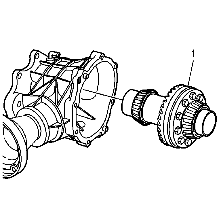
- Remove the carrier assembly (1) from the housing.
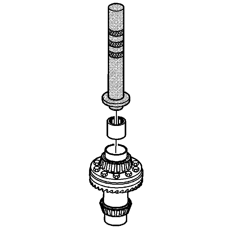
- Using the J 29369-2 and a slide hammer, remove the stub shaft inner bearing from the carrier bore. OTC 8007 adapters may be needed to assist in the removal.
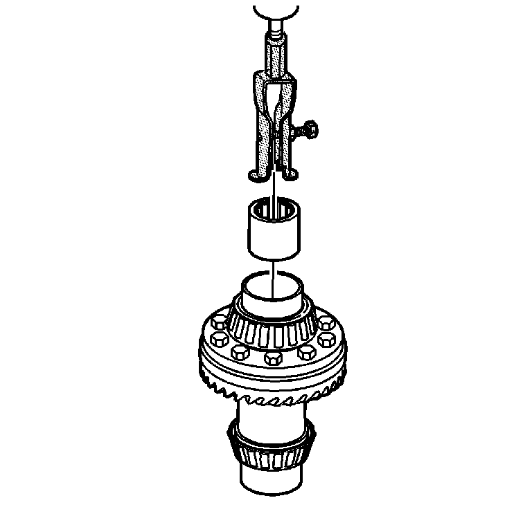
Important: Perform this step only if the bearing needs to be replaced. Do not use the old bearing again.
Installation Procedure
- Using J 4972-4 and a driver, install the axle shaft bearing to the carrier until the bearing seats.
- Clean the carrier assembly housing sealing surface (1) with a solvent and scrape it clean with a razor knife.
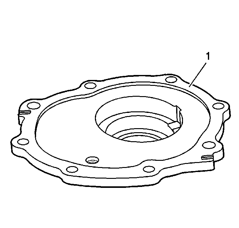
- Clean the cover sealing surface (1) with solvent and scrape it with a razor blade.
- Install the carrier assembly (1) to the housing.
- Apply a 2-3 mm (0.8-0.12 in) amount of sealant GM P/N 1052943 (Canadian P/N 10953491), or equivalent, to the housing (1).
- Install the side cover bolts (1) and the bolts (2 and 3) to the housing.
- Install the transfer case mounting bracket. Refer to Transfer Case Bracket Replacement .
- Using the J 44809 , install the NEW output shaft seal.
- Install the stub shaft using the J 6125-1B and J 38868 .
- Install a NEW retainer ring on the stub shaft.
- Install the intermediate shaft. Refer to Intermediate Shaft Replacement .
- Install the right wheel drive shaft. Refer to Front Wheel Drive Shaft Replacement .
- Fill the transfer case fluid. Refer to Transfer Case Fluid Replacement .
- Lower the vehicle.
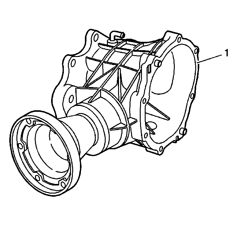
Important: Do not use motor-powered tools to clean surfaces.

Important: Grease the seal lips in order to protect the seal and to ease in assembly.
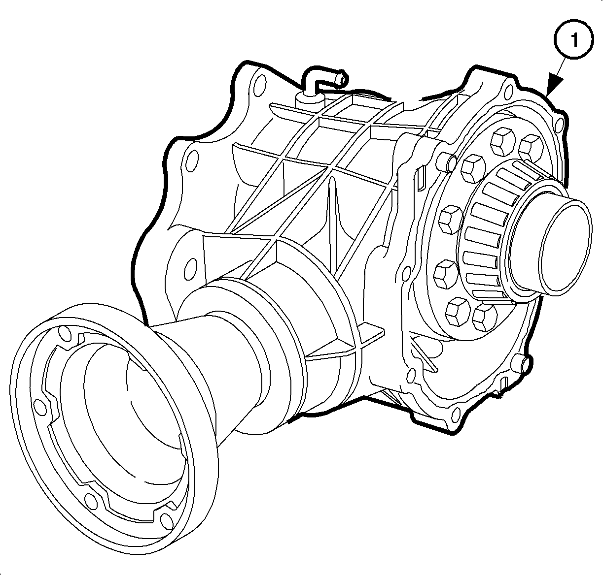
Important: Do not apply excess sealer. Excess sealer could cause premature failure.
Notice: Refer to Fastener Notice in the Preface section.
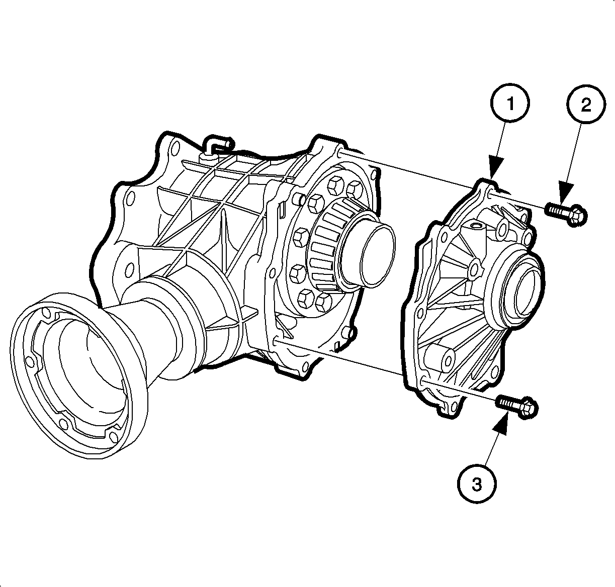
Important: Grease the seal lips in order to protect the seal and to ease in assembly. Coat the bolt threads with thread sealant GM P/N 12345382 (Canadian P/N 10953489).
There is not a specific tightening sequence, but the bolts with the dowel pins should be tightened first, and alternate the others from side to side.
Tighten
Tighten the side cover bolts to 37 N·m (27 lb ft).

