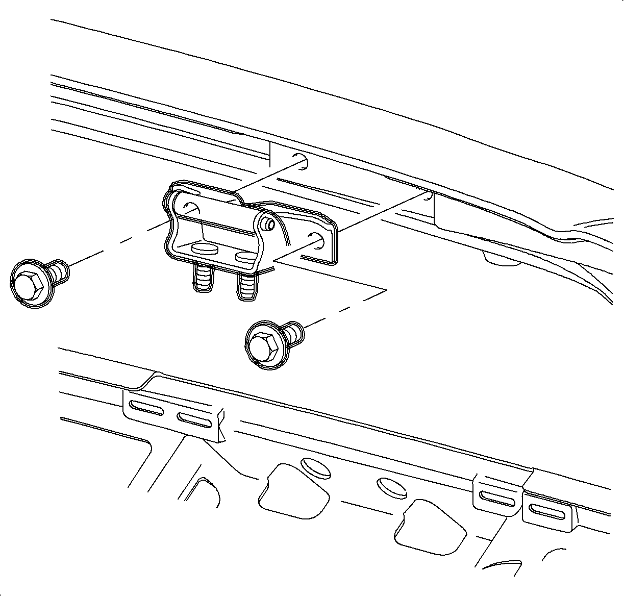
For 1990-2009 cars only
Removal Procedure
- Open the lift gate and support.
- Remove the upper rear garnish molding. Refer to Rear Upper Garnish Molding Replacement .
- Mark the location of the lift gate hinges with a grease pencil.
- Remove the lift gate struts. Refer to Liftgate Strut Replacement .
- Remove the hinge to lift gate bolts.
- Remove the hinge to body nuts.
- Remove the hinges.

Caution: When a lift gate hold open device is being removed or installed, provide alternate support to avoid the possibility of damage to the vehicle or personal injury.
Installation Procedure
- Align the hinge to body alignments marks made in the removal process and install the nuts.
- Align the hinge to lift gate alignment marks made in the removal process and install the bolts.
- Install the lift gate struts. Refer to Liftgate Strut Replacement .
- Lower the lift gate slowly and check for alignment. Align as needed.
- Tighten the nuts to the lift gate hinges.
- Tighten the hinge to lift gate bolts.
- Install the upper rear garnish molding. Refer to Rear Upper Garnish Molding Replacement .

Important: New hinge to body nuts must be used to ensure a proper seal.
Notice: Refer to Fastener Notice in the Preface section.
Tighten
Tighten the hinge to body nuts to 25 N·m (18 lb ft).
Tighten
Tighten the hinge to lift gate bolts to 25 N·m (18 lb ft).
