| Table 1: | Front Compartment Dimensions |
| Table 2: | Body Rear Dimensions |
| Table 3: | Body Side Dimensions |
| Table 4: | Underbody Dimensions |
| Table 5: | Clearance and Flushness Specifications |
Three Dimensional Distance -- X, Y, Z
This universal measuring system is capable of simultaneously dimensioning the length, width, and height of a datum plane. Three dimensional distances are used for both underbody and upperbody measuring.
X = Fore and aft measurements along the center line of the vehicle. An O plane is located forward of the master gage hole at the front of the vehicle 2185 mm as shown. All measurements are made from this plane toward the rear of the vehicle.
Y = Cross car dimensions. Positive values are measured from the center of the vehicle to the right side of the vehicle. Negative values are measured from the center of the vehicle to the left side. When values are not listed separately to change the side of the vehicle, you need only to change the Y dimensions to the opposite value, + or -, from what is listed.
Z = Vertical measurement from the datum plane that is 368 mm below the rocker panel lower flange edge (O plane).
All dimensions are symmetrical, unless otherwise noted.
In order to properly repair the spaceframe, restore the vehicle to the XYZ dimensions, as originally built. Relational (linear) dimensions are for reference only. Use relational dimensions for diagnosis or inspection only. Relational dimensions are not as accurate as XYZ dimensions and measuring systems.
The gage holes shown are the actual fixture locations that are used to build the vehicle.
Thermal Expansion
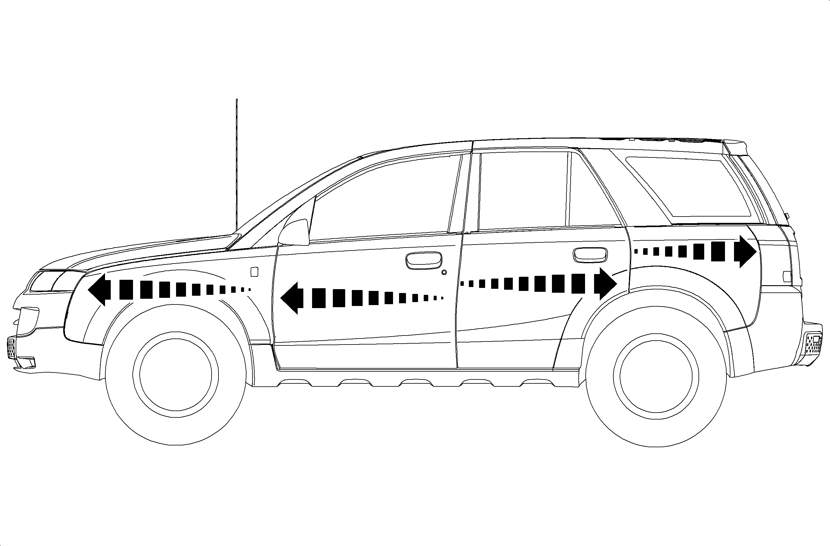
Saturn chose thermal plastic exterior body panels for their strategic advantage. Unique to this technology is the need to manage thermal expansion.
Thermal expansion allows exterior panels, e.g. fender, door quarter, to grow and contract with changes in temperature. The method in which the exterior body controls and directs this expansion is through a carefully engineered fastener system and exterior panel design. This panel design consists of a series of net and slotted holes to direct this growth. The growth is directed forward for the fender and rearward for the quarter panels. The growth of the doors is forward for the front door and rearward for the rear door.
Front Compartment
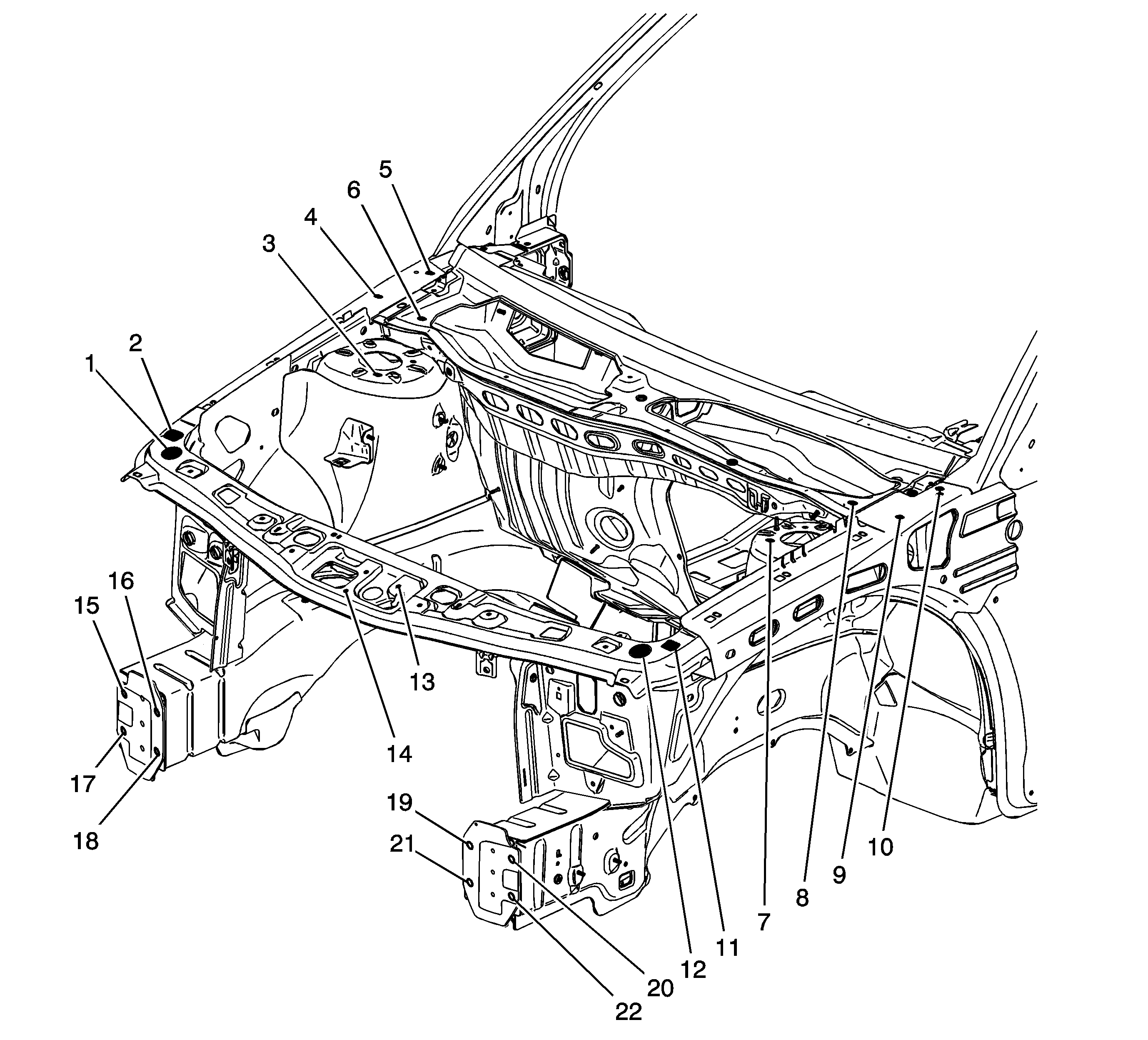
Location | Description | Length = x | Width = y | Height = z | Point to Point |
|---|---|---|---|---|---|
1 | Hood Bumper Hole | 1184 | 649 | 882 | x |
2 | Hole | 1225 | 686 | 889 | x |
3 | Strut Attachment Hole | 1648 | 544 | 934 | x |
4 | Hood Hinge Hole | 1829 | 714 | 978 | x |
5 | Hood Hinge Hole | 1930 | 714 | 9989 | x |
6 | Air Inlet Grille Attachment Hole | 1849 | 600 | 975 | x |
7 | Strut Attachment Hole | 1948 | - 544 | 934 | x |
8 | Air Inlet Grille Attachment Hole | 1813 | -616 | 975 | x |
9 | Hood Hinge Hole | 1829 | - 714 | 978 | x |
10 | Hood Hinge Hole | 1930 | - 714 | 989 | x |
11 | Hole | 1225 | - 689 | 889 | x |
12 | Hood Bumper Hole | 1184 | - 649 | 882 | x |
13 | Hood Striker Attachment Hole | 1080 | -83 | 869 | x |
14 | Hood Striker Attachment Hole | 1018 | - 1 | 852 | x |
15 | Impact Bar Attachment Hole | 921 | - 396 | 480 | x |
16 | Impact Bar Attachment Hole | 943 | - 574 | 480 | x |
17 | Impact Bar Attachment Hole | 943 | - 574 | 405 | x |
18 | Impact Bar Attachment Hole | 921 | - 396 | 405 | x |
19 | Impact Bar Attachment Hole | 921 | - 396 | 480 | x |
20 | Impact Bar Attachment Hole | 943 | - 574 | 480 | x |
21 | Impact Bar Attachment Hole | 943 | - 574 | 405 | x |
22 | Impact Bar Attachment Hole | 921 | - 396 | 405 | x |
15 to 20 | x | x | x | x | 1143 |
18 to 21 | x | x | x | x | 787 |
2 to 11 | x | x | x | x | 1380 |
4 to 11 | x | x | x | x | 1527 |
2 to 9 | x | x | x | x | 1527 |
All dimensions are measured from a zero line, a center line, and a common datum. All dimensions are symmetrical unless otherwise specified. | |||||
Body Rear
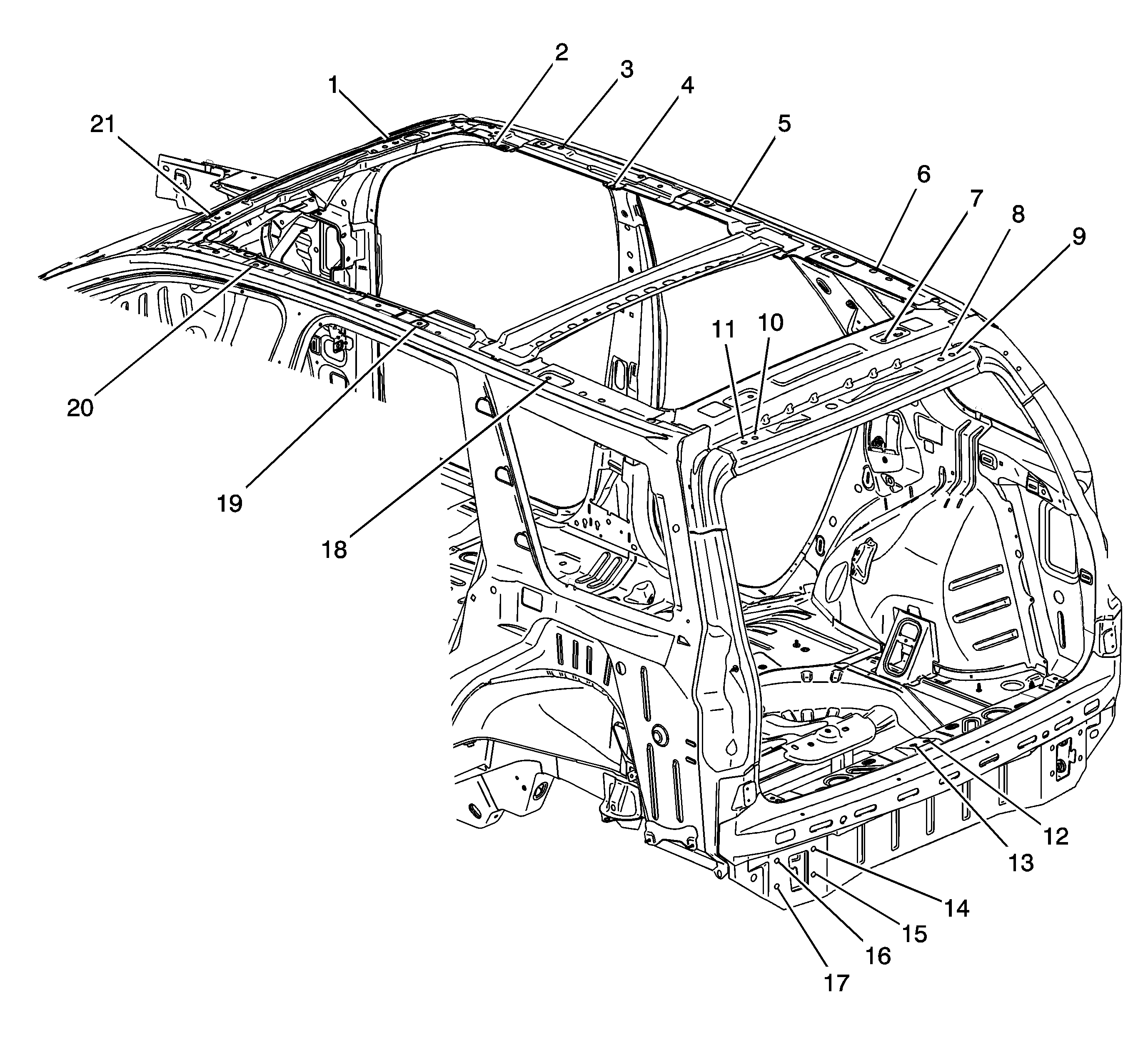
Location | Description | Length = x | Width = y | Height = z | Point to Point |
|---|---|---|---|---|---|
1 | Roof Attachment Hole | 2744 | - 335 | 1525 | x |
2 | Hole | x | x | x | x |
3 | Hole | 3161 | 546 | 1569 | x |
4 | Hole | x | x | x | x |
5 | Hole | 3790 | 546 | 1594 | x |
6 | Hole | 4335 | 546 | 1595 | x |
7 | Roof Attachment Hole | x | x | x | x |
8 | Lift Gate Attachment Hole | x | x | x | x |
9 | Lift Gate Attachment Hole | x | x | x | x |
10 | Lift Gate Attachment Hole | x | x | x | x |
11 | Lift Gate Attachment Hole | x | x | x | x |
12 | Lift Gate Striker Attachment Hole | 5063 | 19 | 628 | x |
13 | Lift Gate Striker Attachment Hole | 5052 | -19 | 624 | x |
14 | Impact Bar Attachment Hole | 5102 | -449 | 483 | x |
15 | Impact Bar Attachment Hole | 5103 | -449 | 403 | x |
16 | Impact Bar Attachment Hole | 5084 | -570 | 483 | x |
17 | Impact Bar Attachment Hole | 5089 | -571 | 407 | x |
18 | Hole | 4200 | -540 | 1595 | x |
19 | Hole | 3715 | -540 | 1595 | x |
20 | Hole | 3100 | -540 | 1564 | x |
21 | Hole | 2744 | -335 | 1525 | x |
From 3 to 21 | x | x | x | x | 1081 |
From 3 to 19 | x | x | x | x | 1496 |
From 6 to 21 | x | x | x | x | 1635 |
From 6 to 19 | x | x | x | x | 1084 |
From 3 to 6 | x | x | x | x | 1157 |
From 19 to 21 | x | x | x | x | 1171 |
From 5 to 20 | x | x | x | x | 1082 |
All dimensions are measured from a zero line, a center line, and a common datum. All dimensions are symmetrical unless otherwise specified. | |||||
Body Side
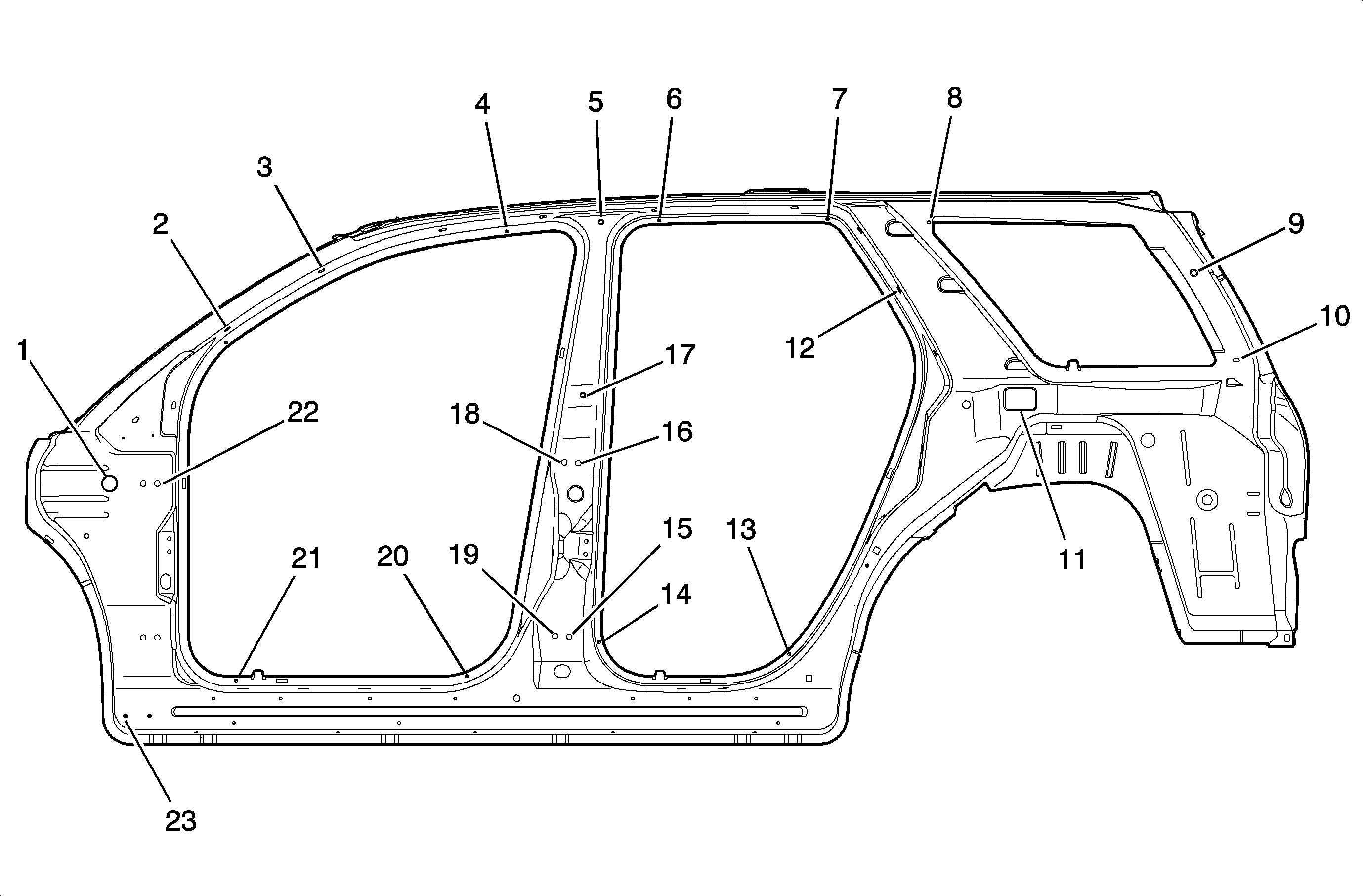
Location | Description | Length = x | Width = y | Height = z | Point to Point |
|---|---|---|---|---|---|
1 | Plug | 2110 | 757 | 875 | x |
2 | Applique Attachment Hole | 2400 | 674 | 1226 | x |
3 | Applique Attachment Hole | 2639 | 642 | 1405 | x |
4 | Die Mark | 3100 | 591 | 1503 | x |
5 | Notch | 3335 | 606 | 1526 | x |
6 | Die Mark | 3480 | 589 | 1530 | x |
7 | Die Mark | 3900 | 595 | 1534 | x |
8 | Hole | 4152 | 643 | 1526 | x |
9 | Hole | 4813 | 673 | 1400 | x |
10 | Hole | 4918 | 733 | 1182 | x |
11 | Hole | 4380 | 777 | 1085 | x |
12 | Hole | 4078 | 704 | 1358 | x |
13 | Die Mark | 3805 | 725 | 450 | x |
14 | Die Mark | 3330 | 725 | 480 | x |
15 | Rear Hinge Attachment Hole | 3256 | 782 | 493 | x |
16 | Rear Hinge Attachment Hole | 3278 | 782 | 926 | x |
17 | Hole | 3290 | 757 | 1095 | x |
18 | Rear Hinge Attachment Hole | 3243 | 782 | 928 | x |
19 | Rear Hinge Attachment Hole | 3221 | 782 | 495 | x |
20 | Die Mark | 3000 | 725 | 395 | x |
21 | Die Mark | 2426 | 725 | 384 | x |
22 | Front Hinge Attachment Hole | 2229 | 762 | 875 | x |
23 | Hole | 2150 | 765 | 296 | x |
From 6 to 13 | x | x | x | x | 1125 |
From 7 to 15 | x | x | x | x | 1224 |
From 4 to 21 | x | x | x | x | 1314 |
From 2 to 20 | x | x | x | x | 1023 |
From 2 to 21 | x | x | x | x | 839 |
From 5 to 23 | x | x | x | x | 1701 |
From 8 to 10 | x | x | x | x | 842 |
All dimensions are measured from a zero line, a center line, and a common datum. All dimensions are symmetrical unless otherwise specified. | |||||
Underbody
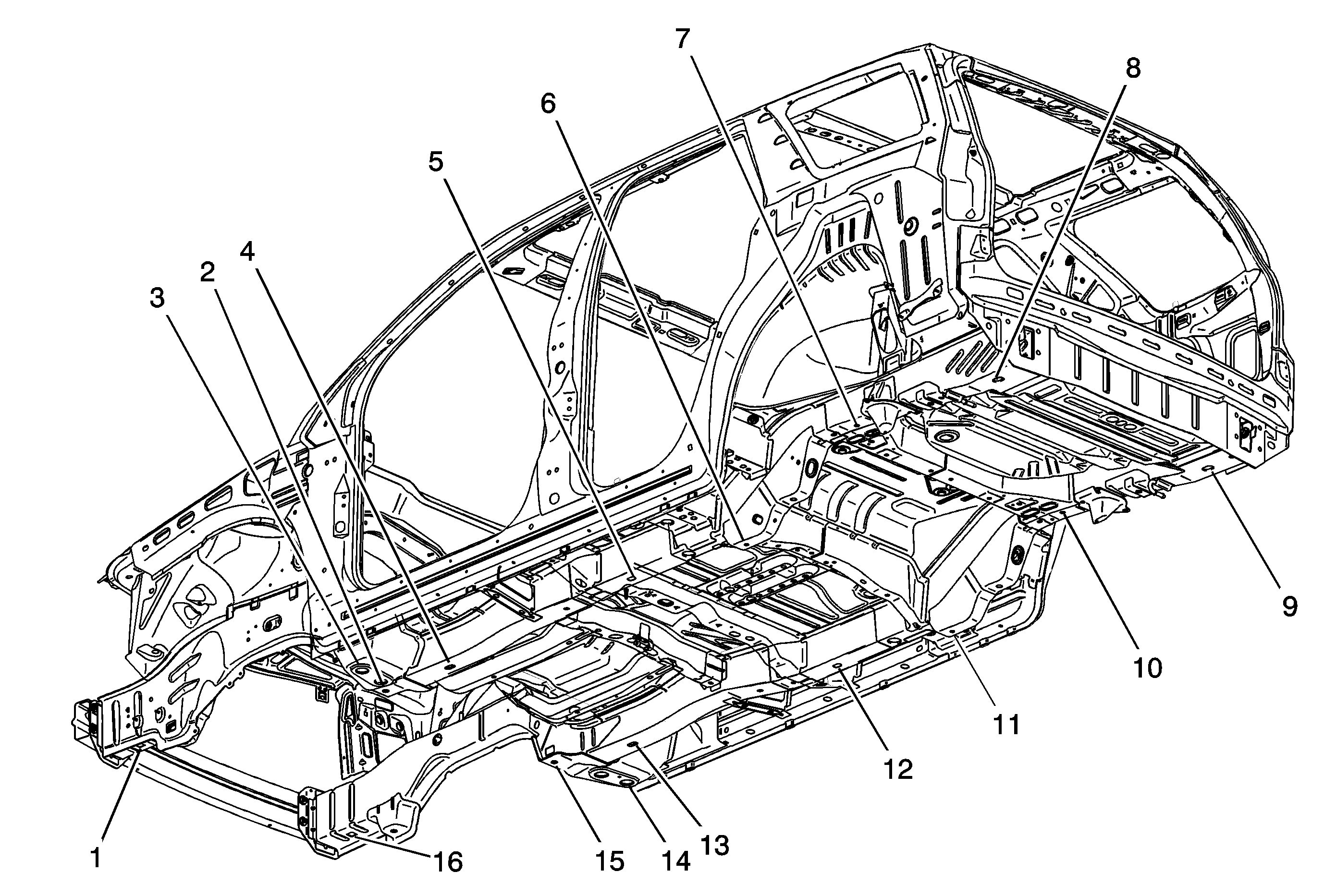
Location | Description | Length = x | Width = y | Height = z | Point to Point |
|---|---|---|---|---|---|
1 | Rear Cradle Mount Hole | 1065 | - 480 | 341 | x |
2 | Hole | 2080 | - 382 | 232 | x |
3 | Hole | 2192 | - 600 | 196 | x |
4 | Hole | 2404 | - 414 | 197 | x |
5 | Hole | 3277 | - 466 | 204 | x |
6 | Hole | 3800 | - 466 | 153 | x |
7 | Hole | 4300 | - 466 | 409 | x |
8 | Hole | 4943 | - 475 | 356 | x |
9 | Hole | 4943 | 475 | 356 | x |
10 | Hole | 4300 | 466 | 409 | x |
11 | Hole | 3800 | 466 | 153 | x |
12 | Hole | 3277 | 466 | 204 | x |
13 | Hole | 2404 | 414 | 197 | x |
14 | Hole | 2192 | 600 | 196 | x |
15 | Rear Cradle Mount Hole | 2081 | 382 | 232 | x |
16 | Hole | 1065 | 480 | 341 | x |
All dimensions are measured from a zero line, a center line, and a common datum. All dimensions are symmetrical unless otherwise specified. | |||||
Clearance and Flushness Specifications
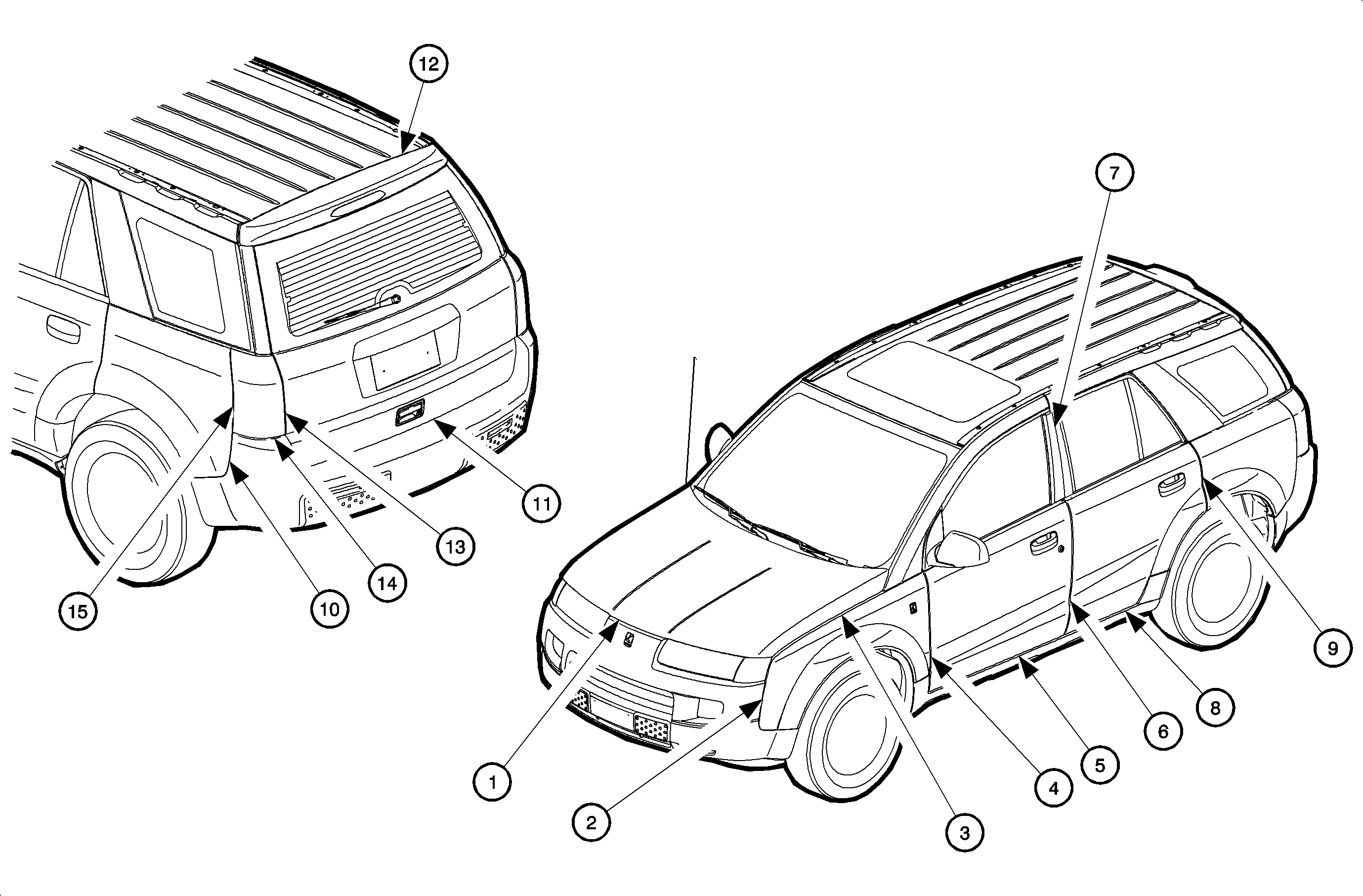
Location | Description | Clearance Gap | Flushness |
|---|---|---|---|
1 | Front fascia to hood | 6.5-9.5 mm (0.25-0.38 in) | -- |
2 | Front fascia to fender | 1.0-3.0 mm (0.04-0.12 in) | -1.5 to 1.5 mm (-0.06 to 0.06 in) |
3 | Front fender to hood | 6.5-9.5 mm (0.25-0.38 in) | -- |
4 | Front fender to front door | 4.50-7.5 mm (0.18-0.30 in) | -1.5 to 1.5 mm (-0.06 to 0.06 in) |
5 | Front door panel to rocker panel | 4.0-10.0 mm (0.16-0.39 in) | -- |
6 | Front door panel to rear door panel | 5.0-8.0 mm (0.2-0.31 in) | -1.5 to 1.5 mm (-0.06 to 0.06 in) |
7 | Front door applique to rear door applique | 6.5+3/-1 mm (0.26+0.12/0.04 in) | -1.5 to 1.5 mm (-0.06 to 0.06 in) |
8 | Rear door panel to rocker | 4.0-10.0 mm (0.16-0.39 in) | -- |
9 | Rear door panel to quarter panel | 4.5-7.5 mm (0.18-0.30 in) | -1.5 to 1.5 mm (-0.06 to 0.06 in) |
10 | Quarter panel to rear fascia | 1.0-3.0 mm (0.04-0.12 in) | -1.5 to 1.5 mm (-0.06 to 0.06 in) |
11 | Lift gate to rear fascia | 6.0-10.0 mm (0.24-0.39 in) | -- |
12 | Lift gate to roof panel | 6.0-10.0 mm (0.24-0.39 in) | 0+1/-2 mm (0+0.0.4/0.08 in) |
13 | Tail lamp to lift gate | 4.0-8.0 mm (0.16-0.31 in) | 0-4.0 mm (0.00-0.16 in) |
14 | Tail lamp to rear fascia | 0-4.0 mm (0.00-0.16 in) | -- |
15 | Tail lamp to quarter panel | 0.5-3.5 mm (0.02-0.14 in) | 0-3.0 mm (0-0.12 in) |
