Frame Replacement L66
Tools Required
| • | J 43828 Ball Joint Remover |
| • | SA9140E Torque Angle Gage |
Removal Procedure
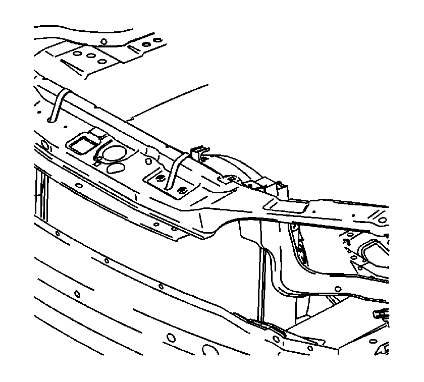
- Tie the radiator, air conditioning condenser, and fan module assembly to the upper radiator support to keep the assembly with the vehicle when the frame is lowered.
- Install the engine support fixture. Refer to Engine Support Fixture .
- Raise and support the vehicle. Refer to Lifting and Jacking the Vehicle .
- Remove the front wheels. Refer to Tire and Wheel Removal and Installation .
- Remove the side splash shield-to-frame fasteners.
- Remove the front air dam-to-frame fasteners.
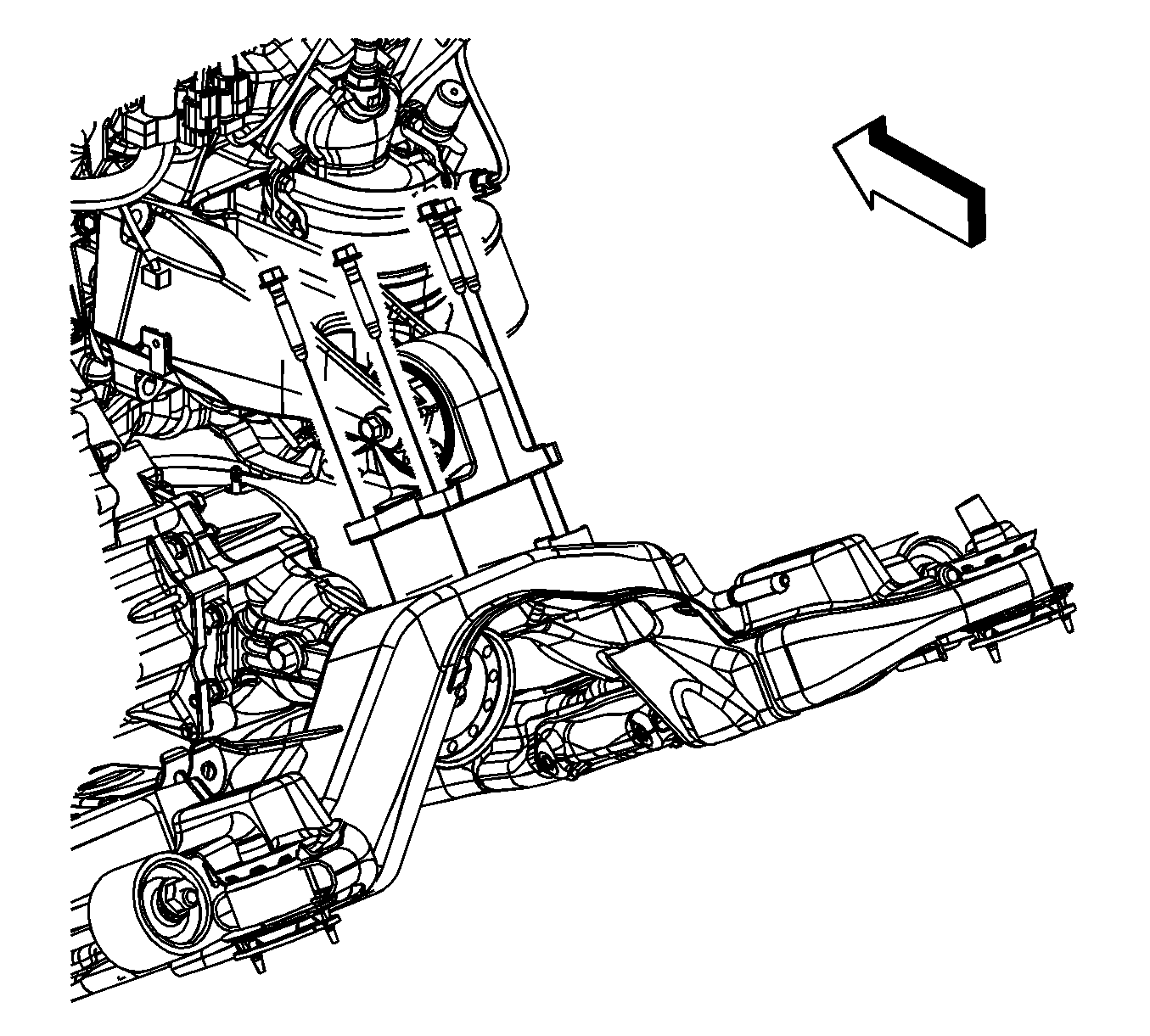
- Remove the rear transmission mount-to-frame bolts.
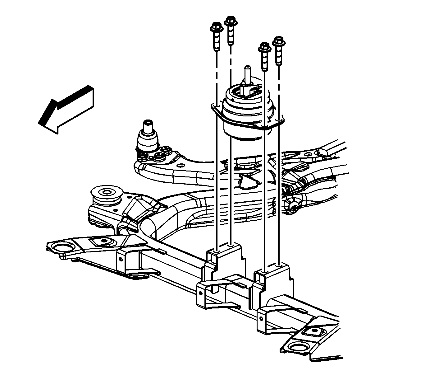
- Remove the front transmission mount-to-frame bolts.
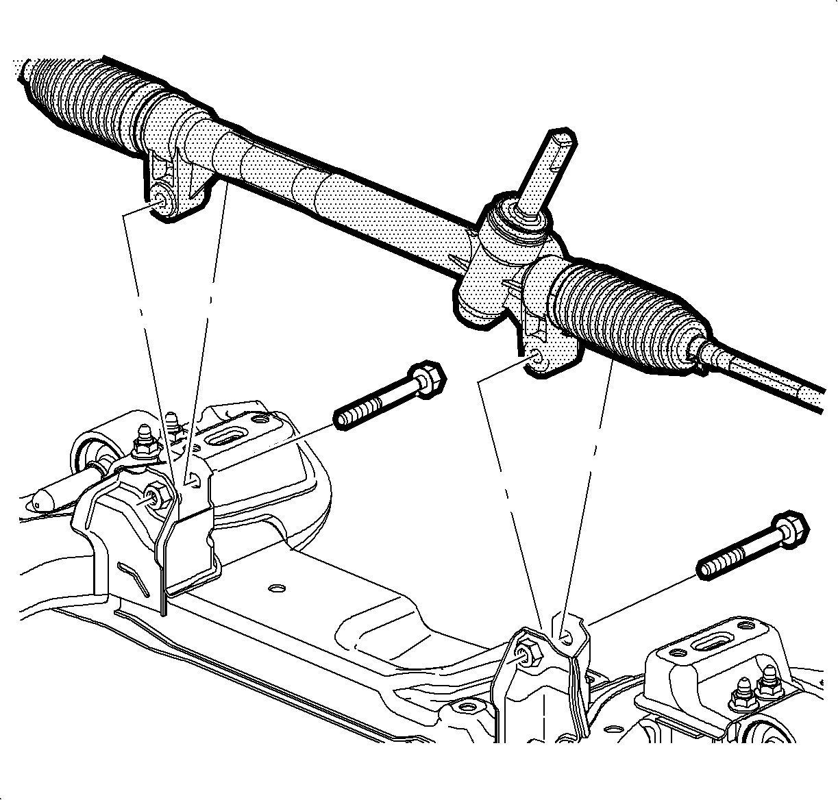
- Remove the steering gear-to-frame bolts.
- Using mechanics wire, secure the steering gear to the exhaust.
- Remove the stabilizer shaft clamp-to-frame bolts.
- Remove the lower ball joint cotter pins. Discard the cotter pins.
- Loosen the lower ball joint castle nut until the nut is level with the top of the ball stud.
- Using the J 43828 , release the ball stud.
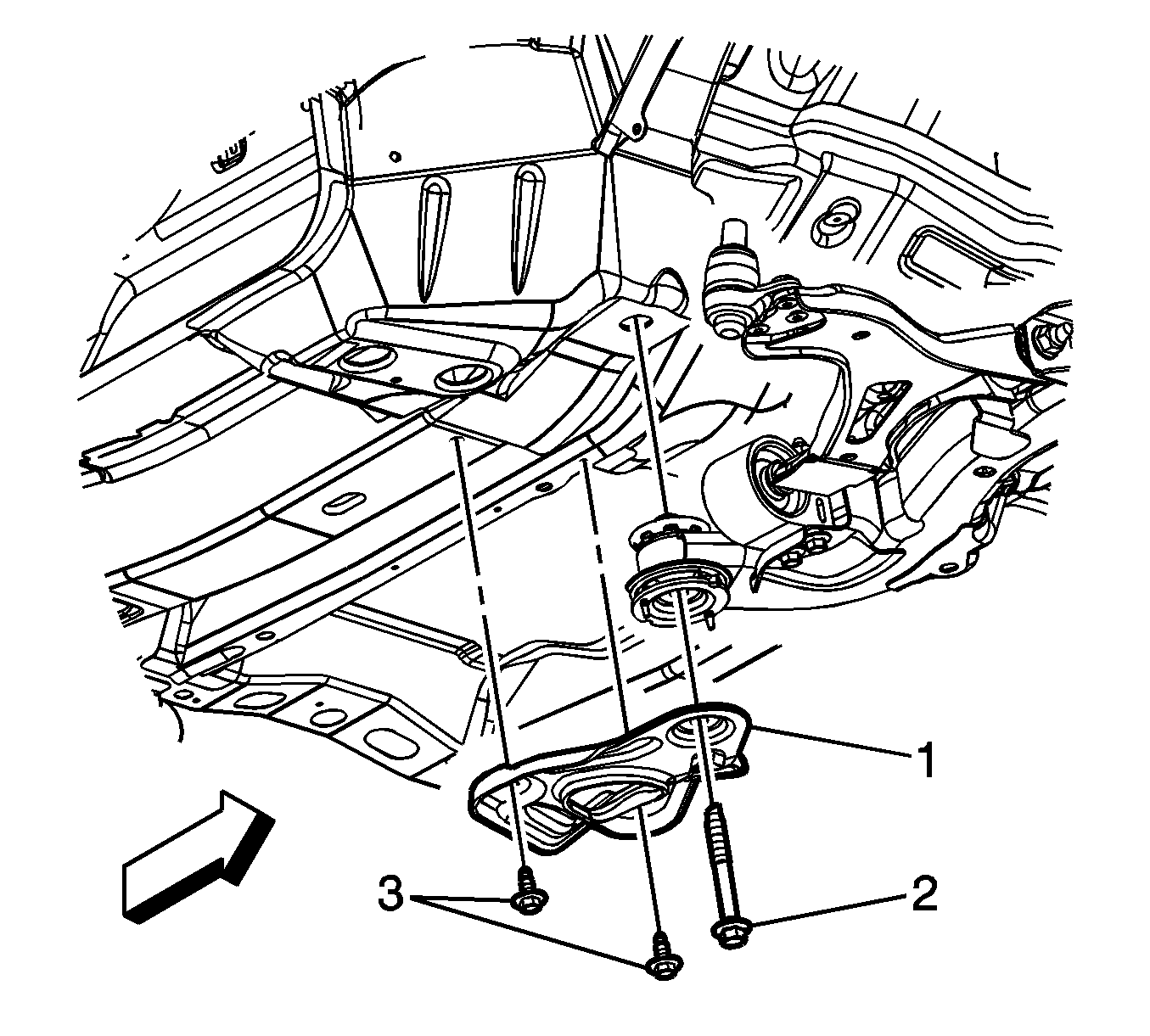
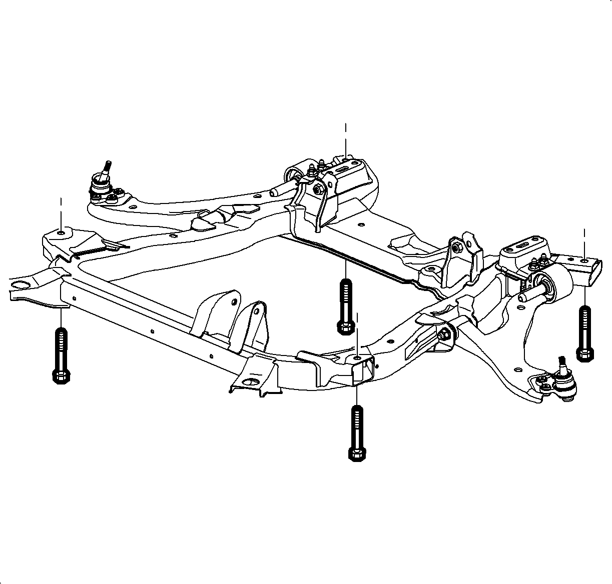
- Remove the reinforcement bolts (3).
- Remove the rear frame to body bolts (2). DISCARD the bolts.
- Remove the reinforcement (1) from the vehicle.
- Remove the front frame-to-body bolts. DISCARD the bolts.
- Carefully lower the frame from the vehicle.
- Remove the lower control arms. Refer to Lower Control Arm Replacement .
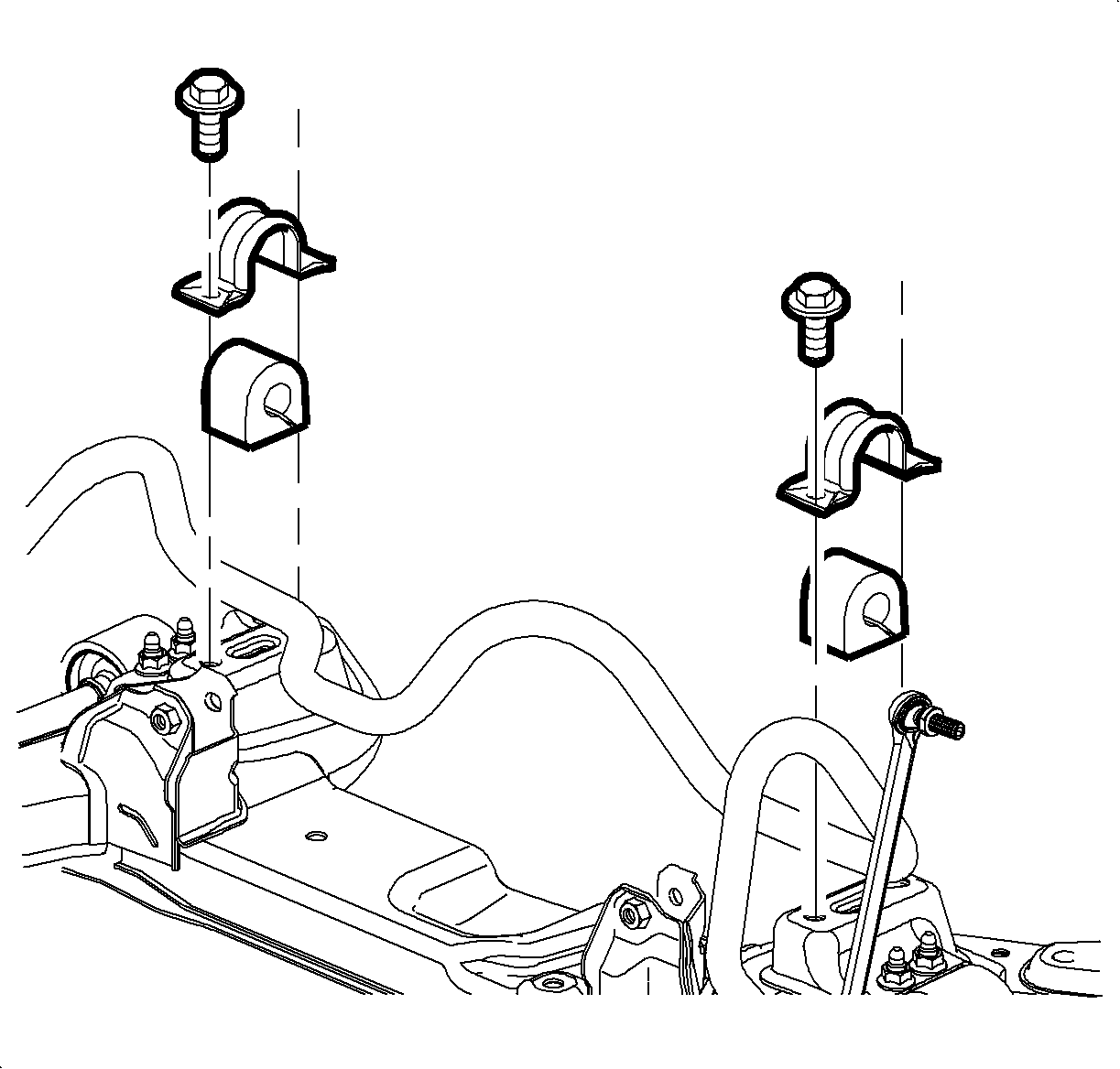
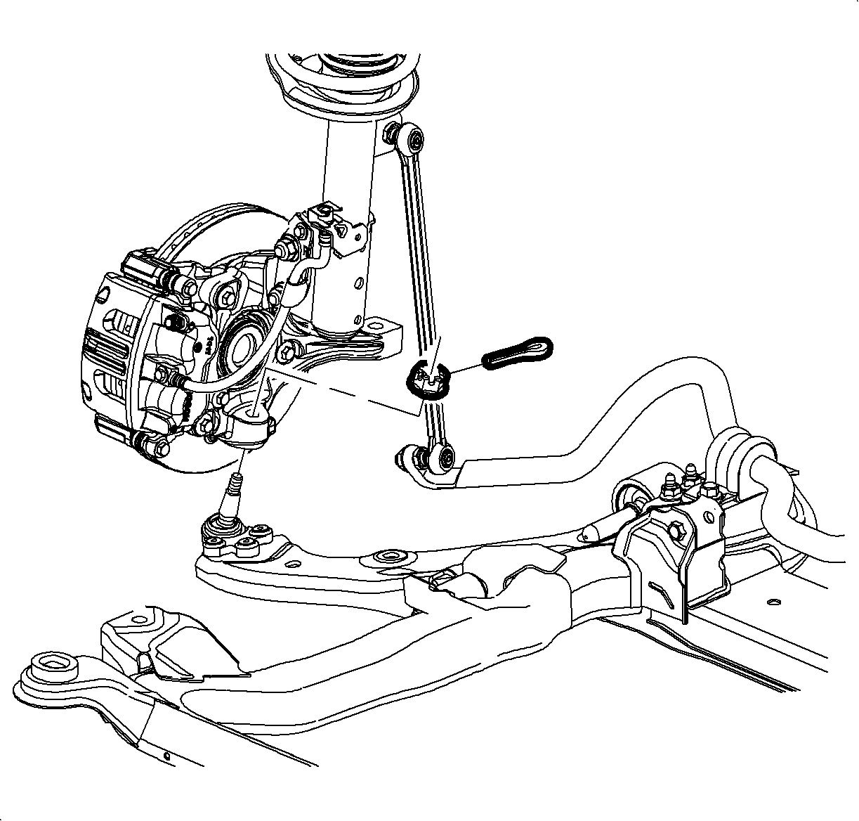
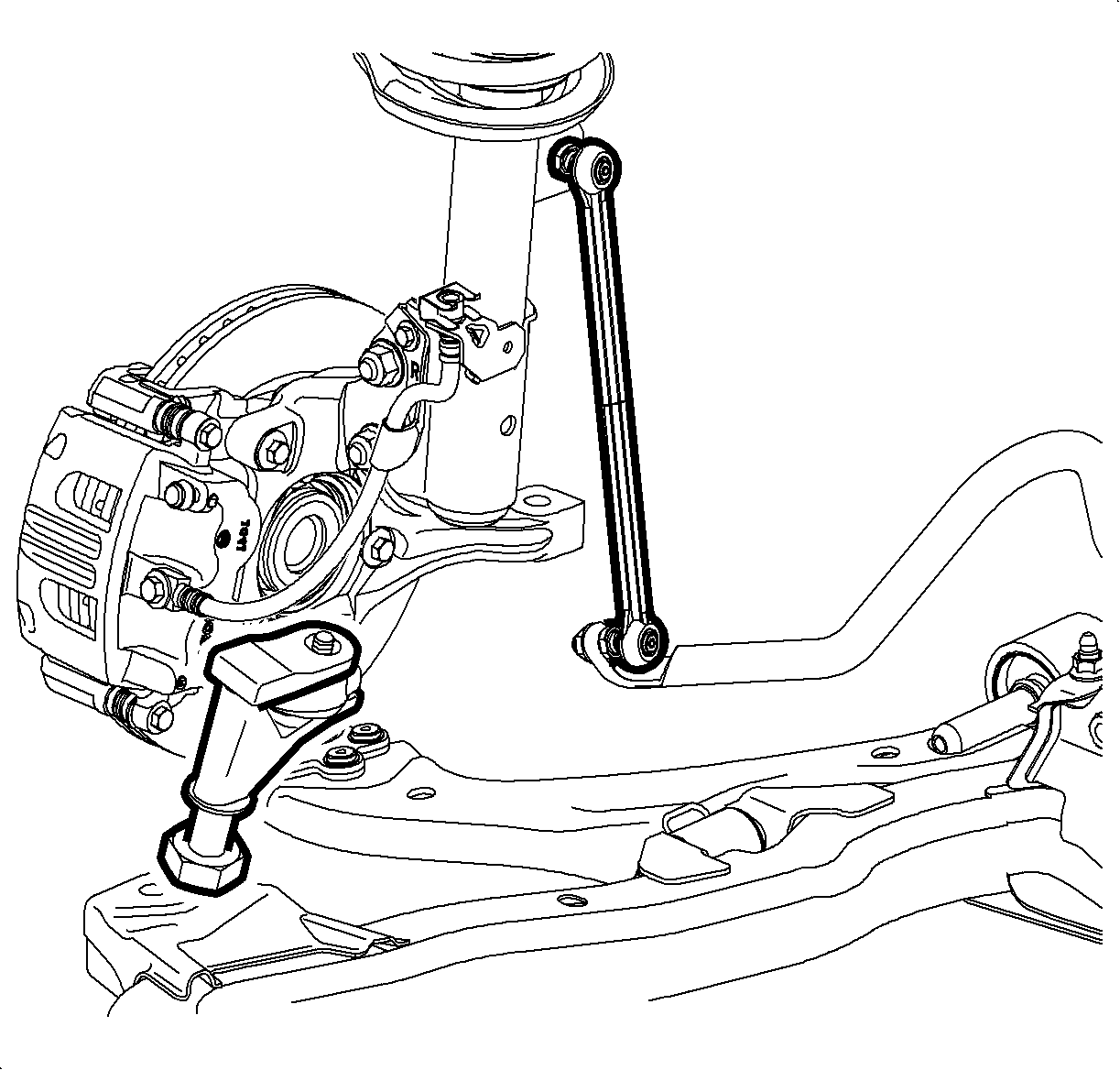
Notice: Do not free the ball stud by using a pickle fork or a wedge-type tool. Damage to the seal or bushing may result.
Installation Procedure
- Install the lower control arms. Refer to Lower Control Arm Replacement .
- Raise the frame to the body.
- Loosely install NEW front frame-to-body bolts.
- Position the reinforcement (1) to the vehicle.
- Loosely install NEW rear frame to body bolts (2).
- Loosely install the reinforcement bolts (3).
- Connect the ball joint stud to the steering knuckle.
- Using the SA9140E , secure the ball stud.
- Continue to tighten the castle nut to align the slots with the opening in the ball stud and install the ball stud cotter pin.
- Remove the mechanics wire and install the steering gear to the frame.
- Install the transmission mount-to-frame bolts.
- Install the rear transmission mount-to-frame bolts.
- Install the stabilizer shaft clamp.
- Tighten the frame-to-body reinforcement bolts (3).
- Tighten the frame-to-body bolts.
- Install the front air dam fasteners.
- Install the side splash shield-to-frame fasteners.
- Install the front wheels. Refer to Tire and Wheel Removal and Installation .
- Lower the vehicle.
- Remove the engine support fixture.
- Untie the radiator, air conditioning condenser, and fan module assembly from the upper radiator support.
- Align the front suspension. Refer to Front Toe Adjustment .

Important: Do not tighten the fasteners at this time.


Notice: Refer to Fastener Notice in the Preface section.
Tighten
Tighten the nut to 40 N·m (30 lb ft).
Important:
• Do not loosen the castle nut in order to align the cotter pin slots. • Ensure the cutter pin ends do not contact the wheel speed sensor harness.

Tighten
Tighten the bolts to 110 N·m (81 lb ft).

Tighten
Tighten the bolt to 50 N·m (37 lb ft).

Tighten
Tighten the bolts to 50 N·m (37 lb ft).
Tighten
Tighten the bolts to 50 N·m (37 lb ft).

Tighten
Tighten the bolts (3) to 50 N·m (37 lb ft).

Tighten
Tighten the bolts to 155 N·m (114 lb ft).
Frame Replacement L61
Tools Required
| • | J 43828 Ball Joint Remover |
| • | SA9140E Torque Angle Gage |
Removal Procedure
- Secure the radiator to the upper radiator support.
- Install the engine support fixture. Refer to Engine Support Fixture .
- Raise and support the vehicle. Refer to Lifting and Jacking the Vehicle .
- Remove the front wheels. Refer to Tire and Wheel Removal and Installation .
- Remove the side splash shield-to-frame fasteners.
- Remove the front air dam-to-frame fasteners.
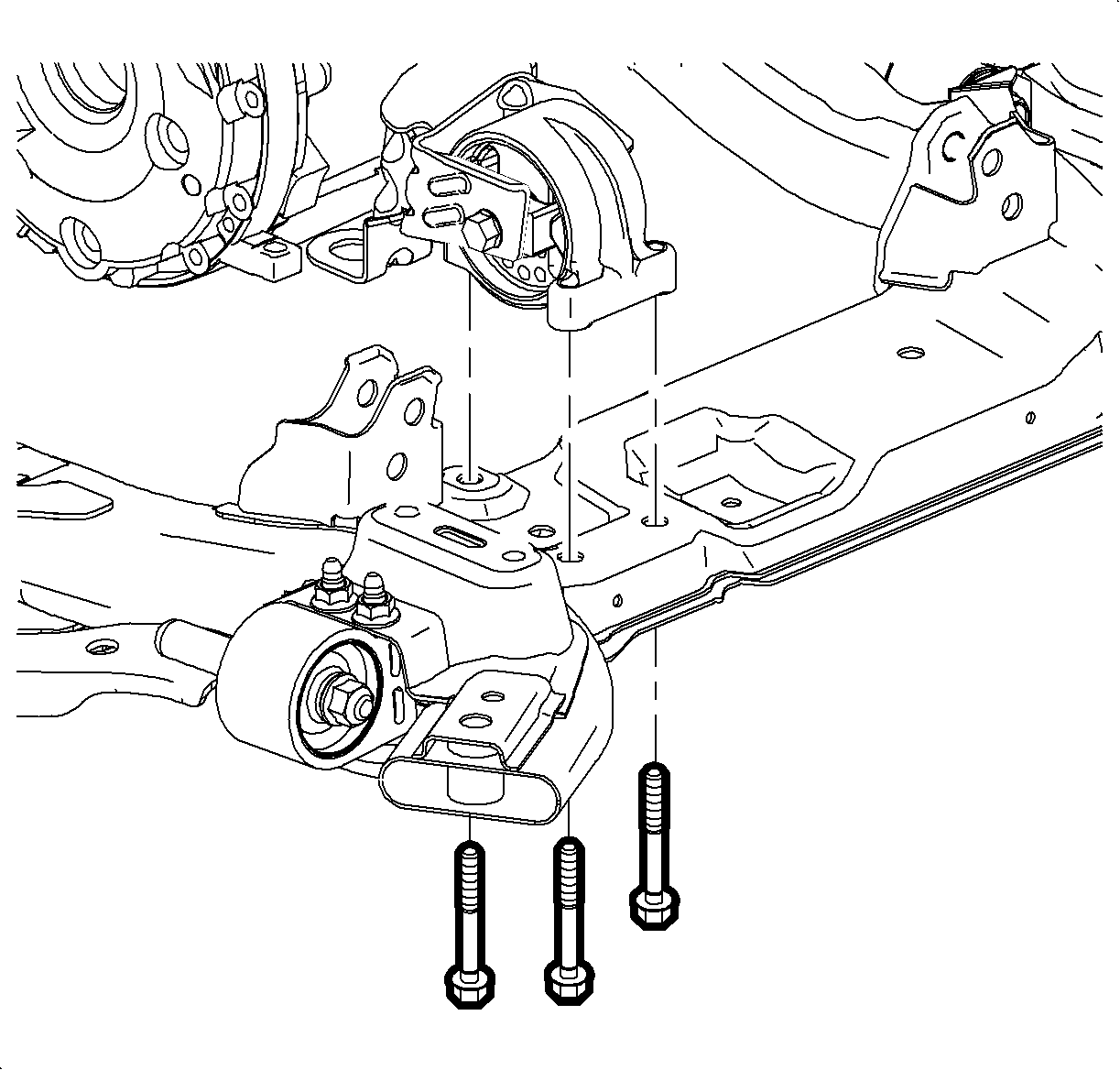
- Remove the rear transaxle mount-to-frame bolts.
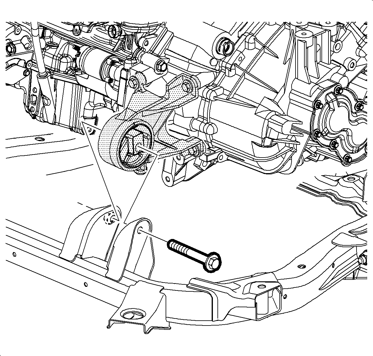
- Remove the front transaxle mount through bolt.
- Remove the steering gear-to-frame bolts.
- Using mechanics wire, secure the steering gear to the exhaust.
- Remove the stabilizer shaft clamp-to-frame bolts.
- Remove the lower ball joint cotter pins. Discard the cotter pins.
- Loosen the lower ball joint castle nut until the nut is level with the top of the ball stud.
- Using the J 43828 , release the ball stud.
- Remove the frame-to-body bolts. Discard the bolts.
- Carefully lower the frame from the vehicle.
- Remove the lower control arms. Refer to Lower Control Arm Replacement .



Notice: Do not free the ball stud by using a pickle fork or a wedge-type tool. Damage to the seal or bushing may result.

Installation Procedure
- Install the lower control arms. Refer to Lower Control Arm Replacement .
- Raise the frame to the body.
- Loosely install new frame-to-body bolts.
- Connect the ball joint stud to the steering knuckle.
- Using the SA9140E , secure the ball stud.
- Continue to tighten the castle nut to align the slots with the opening in the ball stud and install the ball stud cotter pin.
- Remove the mechanics wire and install the steering gear to the frame.
- Install the front transaxle mount through bolt.
- Install the rear transaxle mount-to-frame bolts.
- Install the stabilizer shaft clamp.
- Tighten the frame-to-body bolts.
- Install the front air dam fasteners.
- Install the side splash shield-to-frame fasteners.
- Install the front wheels. Refer to Tire and Wheel Removal and Installation .
- Lower the vehicle.
- Remove the engine support fixture. Refer to Engine Support Fixture .
- Unsecure the radiator from the upper radiator support.
- Align the front suspension. Refer to Front Toe Adjustment .

Important: Do not tighten the fasteners at this time.

Notice: Refer to Fastener Notice in the Preface section.
Tighten
Tighten the nut to 40 N·m (30 lb ft).
Important:
• Do not loosen the castle nut in order to align the cotter pin slots. • Ensure the cutter pin ends do not contact the wheel speed sensor harness.

Tighten
Tighten the bolts to 110 N·m (81 lb ft).

Tighten
Tighten the bolt to 110 N·m (81 lb ft).

Tighten
Tighten the bolts to 50 N·m (37 lb ft).
Tighten
Tighten the bolts to 50 N·m (37 lb ft).
Tighten
Tighten the bolts to 155 N·m (114 lb ft).
