| Subject: | Hybrid Battery Light On, Illumination of SES with DTC P0A4B [may set DTC P0AA1 in addition to P0A4B], SGCM, MGU, Starter/Generator, Hybrid Resolver Circuit (Install Engine Wiring Harness Jumper) |
| Models: | 2007 Saturn VUE Hybrid |
| with 2.4L Engine (VIN Z -- RPO LAT) |
Condition
Some customers may comment that the battery light or SES is on. Upon further diagnosis, the technician will find that DTC P0A4B has set. In most instances, a P0AA1 will also be stored with the P0A4B DTC. When the battery light is illuminated, the SGCM
is not charging the 12 volt or 36 volt batteries. As a result, the 12 volt battery could discharge if the vehicle is driven continuously with the battery light on.
Cause
This condition may be caused by high resistance on the resolver circuits.
Correction
DO NOT REPLACE THE SGCM, THE STARTER/GENERATOR (MGU) OR THE ENGINE WIRING HARNESS.
To correct this condition, use the following procedure:
- Reprogram the PCM with the service calibration (P/N 12616396 -- Enhanced Hybrid Diagnostics and Enhanced Cruise Control Performance) released on TIS2WEB version 12.5 or later.
- Install an engine wiring harness jumper (between the SGCM and MGU) using the following procedure:
| 2.1. | Perform the Hybrid Battery Service Disconnect procedure found in SI. |
| 2.2. | Disconnect the 12V battery negative cable. |
| 2.3. | Remove the air cleaner outlet duct. |
| 2.4. | Disconnect the SGCM C1 (Black) and C2 (Grey) connectors. |
| 2.5. | Reroute the SGCM C1 (Black) connector so that it is underneath the vacuum hose. |
| 2.6. | Remove the conduit and tape between the SGCM C2 (Grey) connector and main harness. |
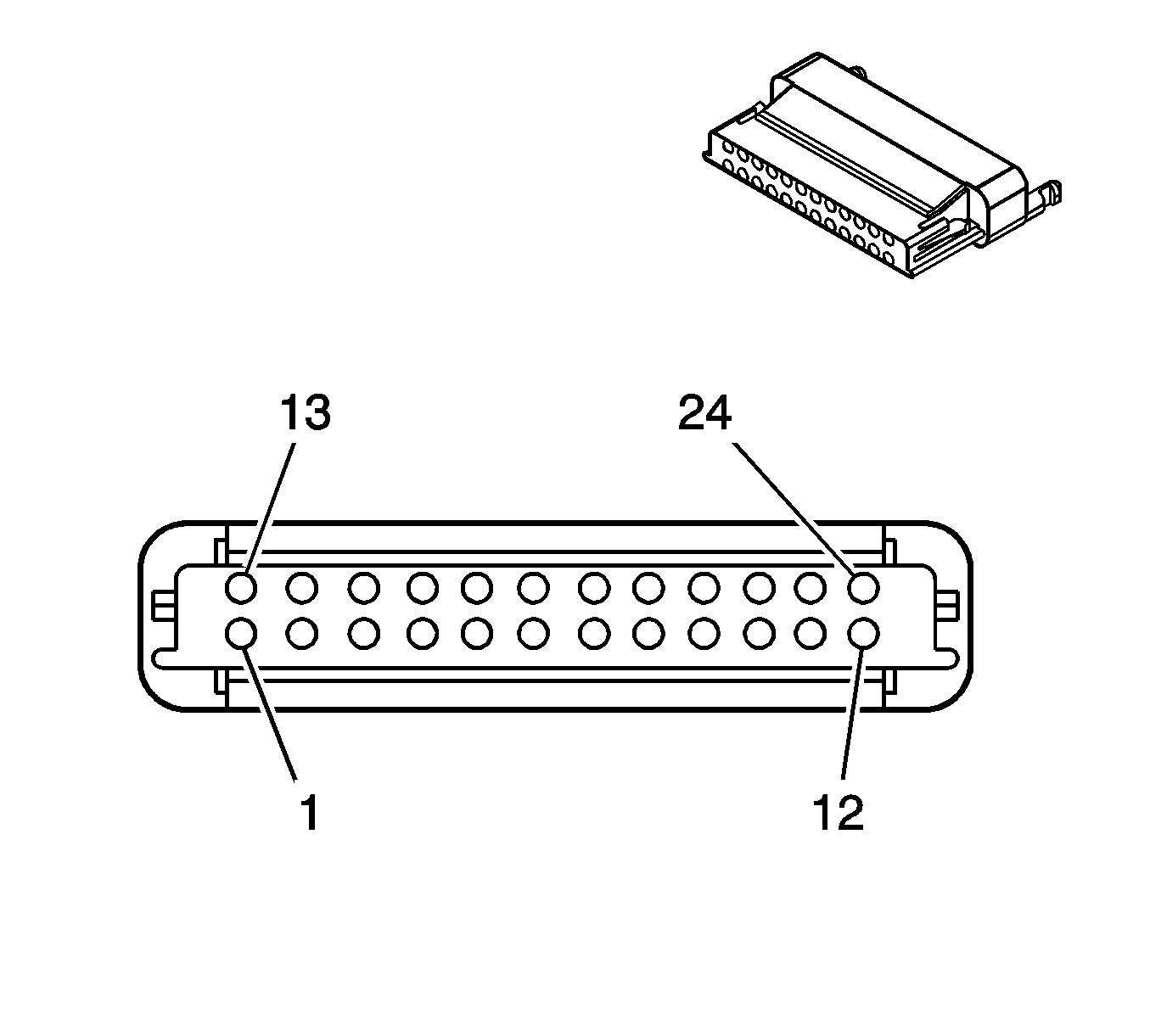
SGCM C2 (Grey) Connector:

| 2.7. | From the C2 Connector, carefully remove the following four circuits from the old 24W connector. These four circuits will be installed in the new SGCM C2 connector in the wiring harness jumper. |
Tip
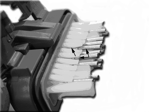
To remove the circuit/terminal from the connector, remove the clear cover, then while pulling up on the white "finger", slightly pull up on the pin while pushing it in. Refer to the C2 Connector Circuit/Terminal Removal
diagram.
C2 Connector -- Circuit/Terminal Removal:

| | Important:
| • | Make sure the four circuits listed above are NOT cut. |
| • | The connector removed from the original wiring harness will need to be returned to engineering. This part may be requested from the dealership using the WPC return process. |
|
| 2.8. | Cut off the remaining circuits just after the connector (C2). This will leave approximately 51 mm (2 in) remaining from the main bundle to the end of the stub. |
| 2.9. | Tape the end of the wires (stub) with high temperature electrical tape. |
| 2.10. | Tie strap the stub to the engine harness. |
| | Important: When installing the circuits into the new SGCM connector, do not twist or wrap the wires. This can cause the wiring to become too tight.
|
| 2.11. | Install the four circuits (1, 3, 8 and 21) into the SGCM C2 connector of the wiring harness jumper. Be careful not to bend the terminals. After installing the four circuits into the new connector, replace the clear connector cover. |
| 2.12. | Install conduit over the four circuits and tape in place. Start the conduit at the main bundle to insure all of the wiring is covered. |
| 2.13. | Reconnect the SGCM C1 and C2 connectors. |
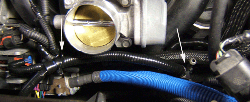
| 2.14. | Route the wiring harness jumper under the brake vacuum hose, coolant hose and main engine harness bundle then back up and over to the MGU. Refer to the following diagram. |

| | Important:
| • | DO NOT cut the 8-way connector at the MGU. |
| • | The connectors removed from the original wiring harness will need to be returned to engineering. The connectors may be requested from the dealership using the WPC return process. |
|
| 2.15. | Remove both MGU (10-way resolver and 7-way field and thermistor) connectors and connect the new MGU connectors from the jumper harness. |
| 2.16. | Tie strap the wiring harness jumper to the rear of the silver post and to the existing engine harness, utilizing the tie straps on the jumper. Refer to the above diagram. |
| 2.17. | Cut off the old MGU connectors (on the main engine wiring harness) at the end of the conduit. |
| 2.18. | Tape the end of the wires (stub) with high temperature electrical tape and tie strap back to the engine harness. |
| 2.19. | Make sure nothing (i.e. forward lamp harness, shifter cable, etc) is interfering with the wiring harness jumper routing. |
| 2.20. | Reinstall the air cleaner outlet. |
| 2.21. | Reconnect the 12V battery. |
| 2.22. | Reconnect the Hybrid battery. |
- Test drive the vehicle to confirm that the customer's concern has been corrected. If the condition has not been corrected, contact GM Technical Assistance for further diagnostic and repair information.
Parts Information
Part Number
| Description
|
25892536
| Harness Asm -- Engine Wiring (Jumper)
|
Warranty Information
For vehicles repaired under warranty, use:
Labor Operation
| Description
| Labor Time
|
J7715 *
| Harness Asm - Engine Wiring Jumper - Install
| 0.9 hr
|
* This labor operation number is for bulletin use only. This number will not be published in the Labor Time Guide.
|


