Check Engine Light On, Battery Warning Light On DTC P1A5A and/or P1A59 Set (Inspect Hybrid Batteries for Voltage Imbalance or Corrosion, Replace Batteries, If Necessary)

| Subject: | Check Engine Light On, Battery Warning Light On, DTC P1A5A and/or P1A59 Set (Inspect Hybrid Batteries for Voltage Imbalance or Corrosion, Replace Batteries, if Necessary) |
| Models: | 2007 Saturn AURA Greenline Hybrid |
| 2007 Saturn VUE Greenline Hybrid |
| with 2.4L Engine (VIN Z - RPO LAT) |
This bulletin is being revised to add information to the Subject line, update the service procedure for both VUE and AURA to include steps to transfer temperature sensors to the new batteries. Also, the part number for the battery has changed. Please discard Corporate Bulletin Number 07-06-03-006 (Section 06 -- Engine/Propulsion System).
Condition
Some customers may comment on a Check Engine light and/or Battery Warning light being illuminated.
A scan tool may reveal DTC P1A59 set. Typically, this will be the only DTC stored, but on occasion, DTC P1A5A may also be stored as a secondary DTC.
Correction
Inspect the hybrid batteries for module voltage imbalance or corrosion. If the hybrid battery module imbalance exceeds 0.6 volts or if corrosion is present, replace the 3 batteries using the procedure below.
Service Procedure (VUE)
Important: Dust may be an irritant to skin and eyes. Avoid skin and eye contact. If battery dust is present, remove carefully to avoid inhalation. Wear safety glasses and butyl rubber, natural rubber, neoprene, nitrile or Tyvek protective gloves when handling any corroded hybrid batteries and when cleaning the inside of the hybrid battery case. Discard the gloves after each use and dispose of any corrosion material that was removed from the case.
- Remove the ignition key from the ignition switch. Secure the ignition key in order to ensure that the key CANNOT be re-installed without your knowledge.
- Disconnect the 12 volt negative battery cable.
- Remove the rear compartment closeout panels.
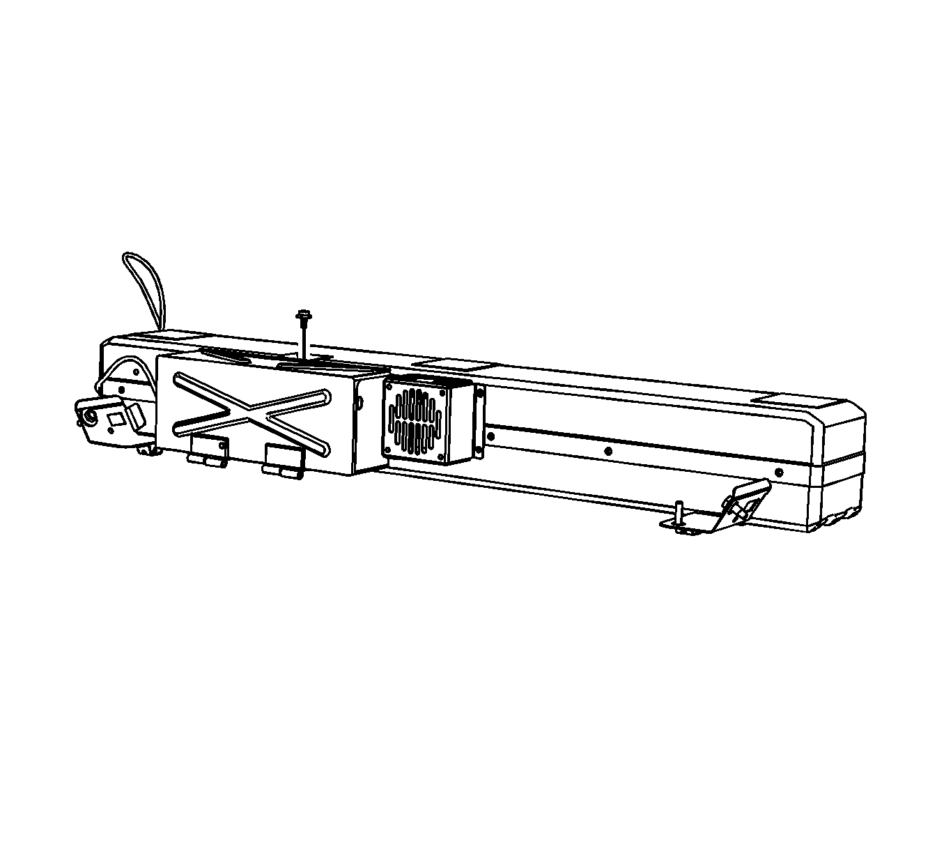
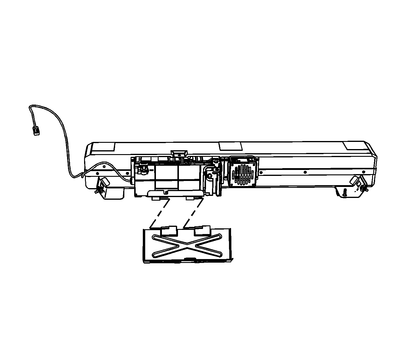
- Remove the generator battery disconnect control module cover bolt .
- Slide the generator battery disconnect control module cover to the right and remove the cover.
- WAIT at least 5 minutes in order to allow the generator control module capacitors to discharge.
- The generator battery will have to be checked for voltage potential using a voltmeter. First, verify that the voltmeter works.
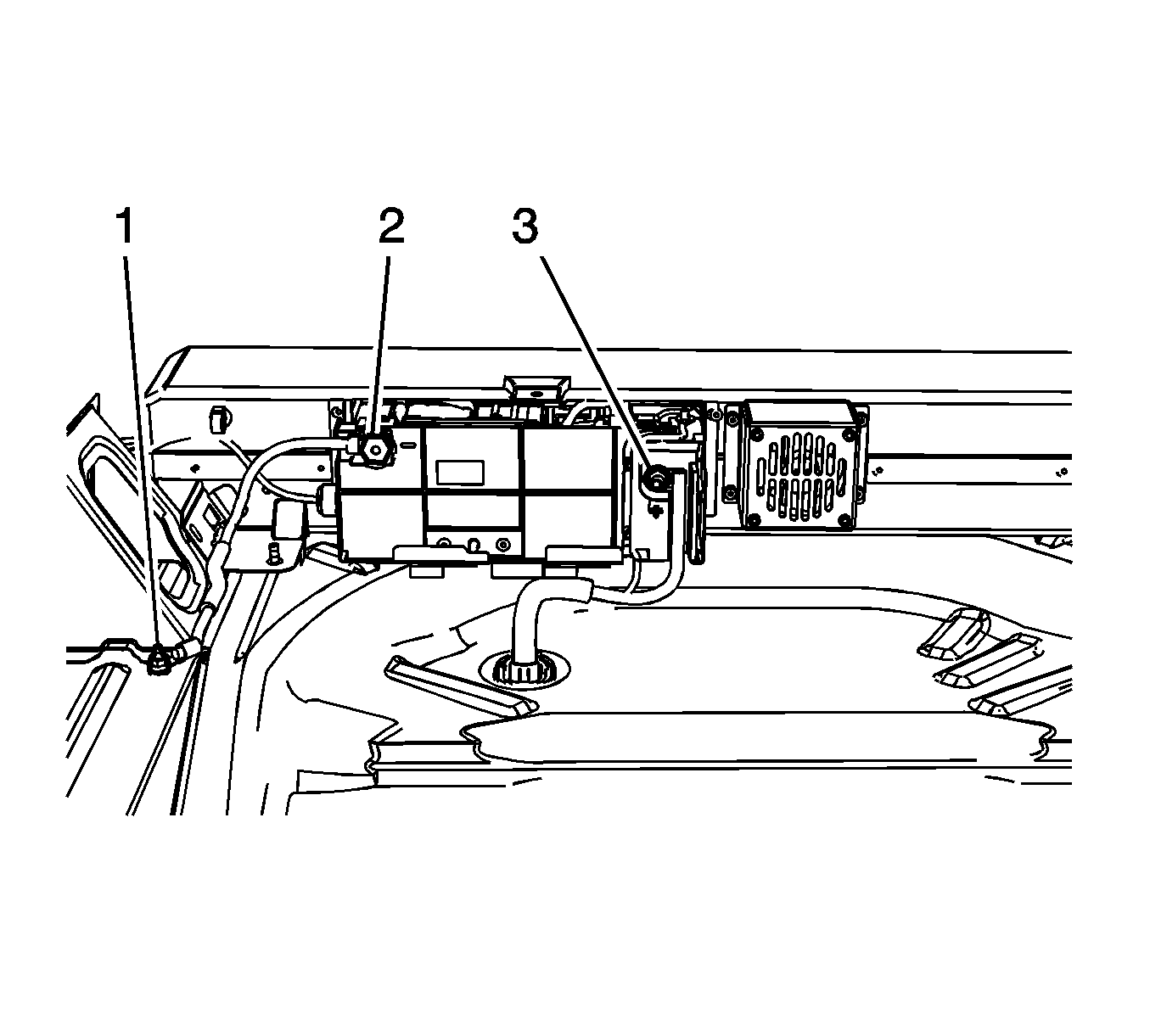
- Now, check the generator battery for voltage potential in order to ensure that the generator battery has been disabled.
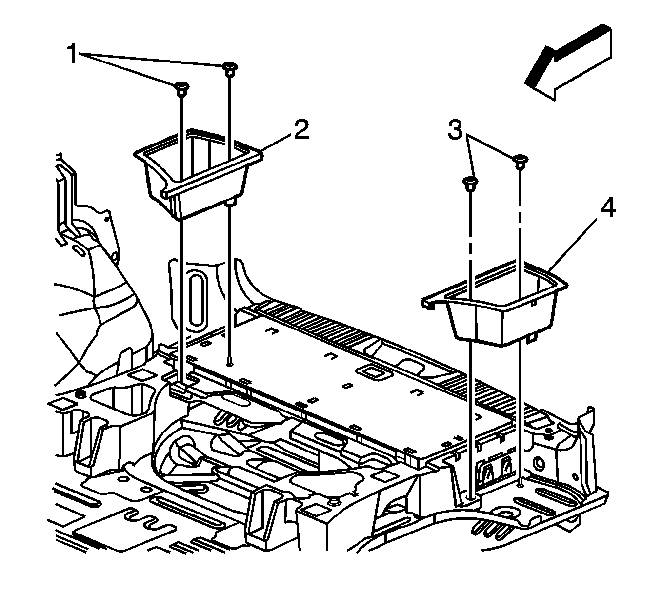
- Remove the driver and passenger side rear compartment load floor stowage tray retainers (1, 3).
- Remove the driver and passenger side rear compartment load floor stowage trays (2, 4).
- Carefully remove the driver and passenger side foam insulators.
- Fold down the rear seat back.
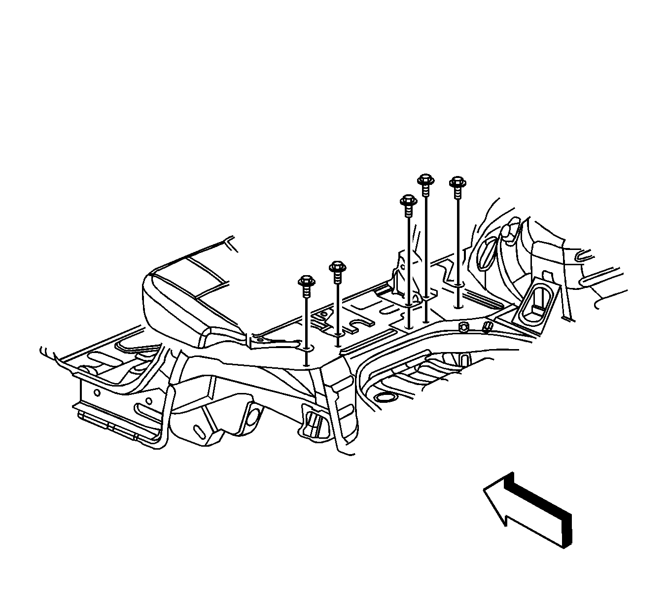
- Remove the rear seat rear bolts.
- Partially remove the left side rear quarter lower trim panel.
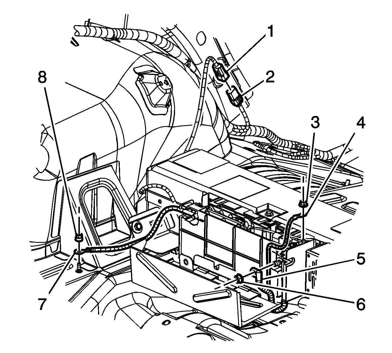
- Disconnect the generator battery wiring harness electrical connector (1) from the body wiring harness electrical connector (2).
- Remove the 36 volt negative battery cable ground nut (8) and cable from body stud.
- Remove the cable shield lead nut (3) and cable lead (4) from the carrier.
- Remove the 36 volt positive battery cable lead nut (6).
- Remove the 36 volt positive battery cable lead (5).
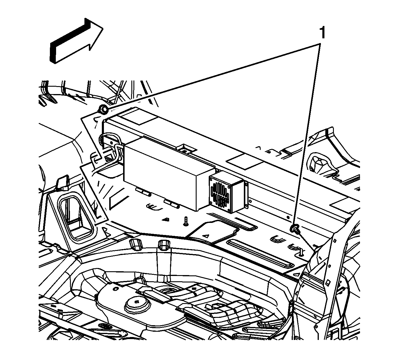
- Remove the generator battery front bolts (1) at the shock towers.
- Pull the generator battery carrier towards the rear of the vehicle and carefully remove the carrier from the vehicle. Place the carrier assembly on a workbench.
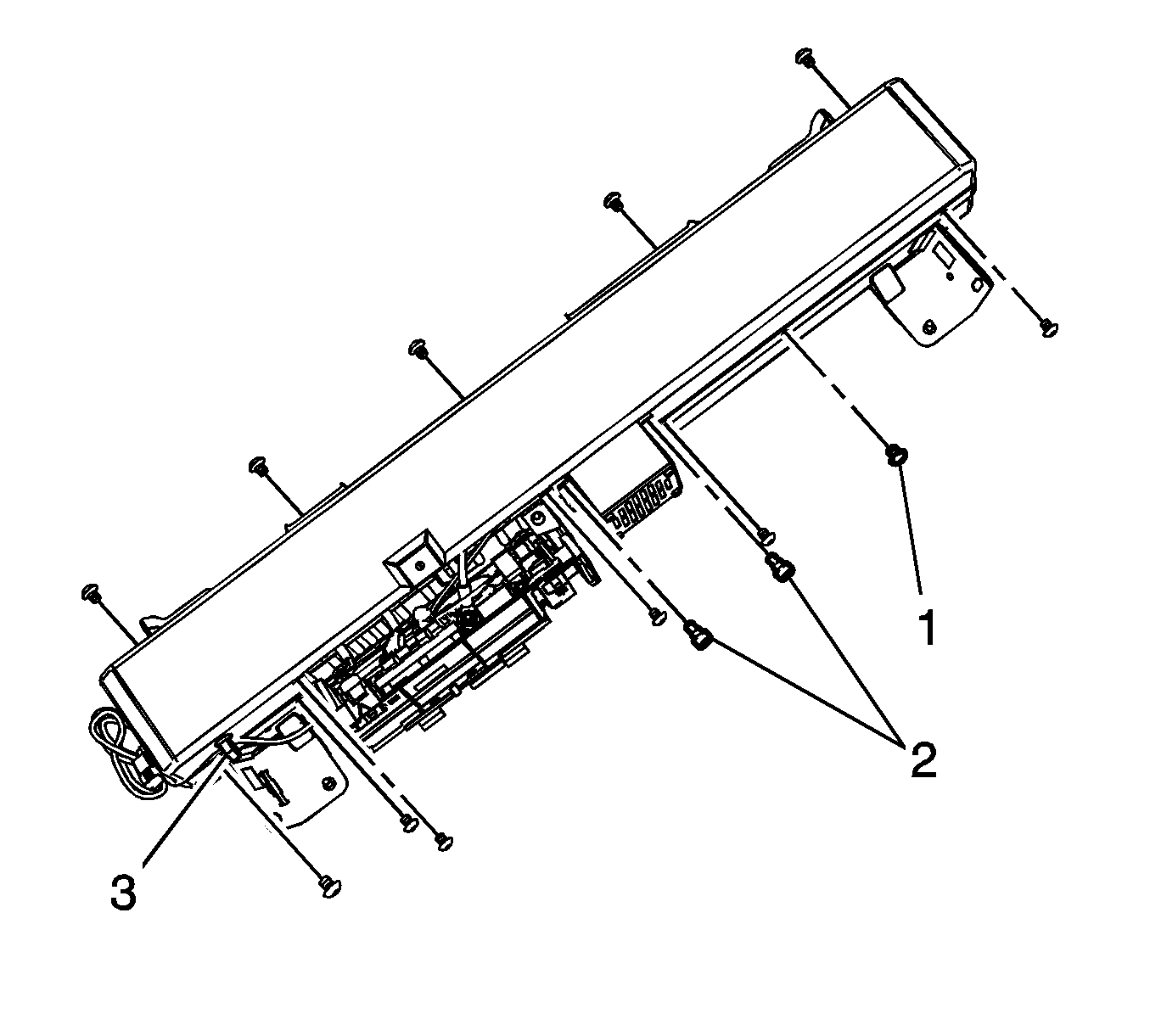
- Remove the two upper generator battery fan bolts (2).
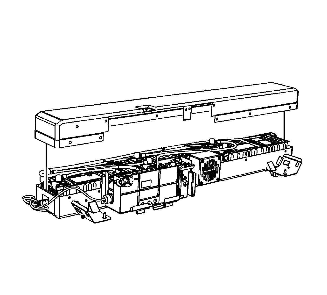
- Remove the 12 generator battery cover bolts (1).
- Remove the generator battery wiring harness from the clip (3) on the generator battery cover.
- Remove the generator battery cover.
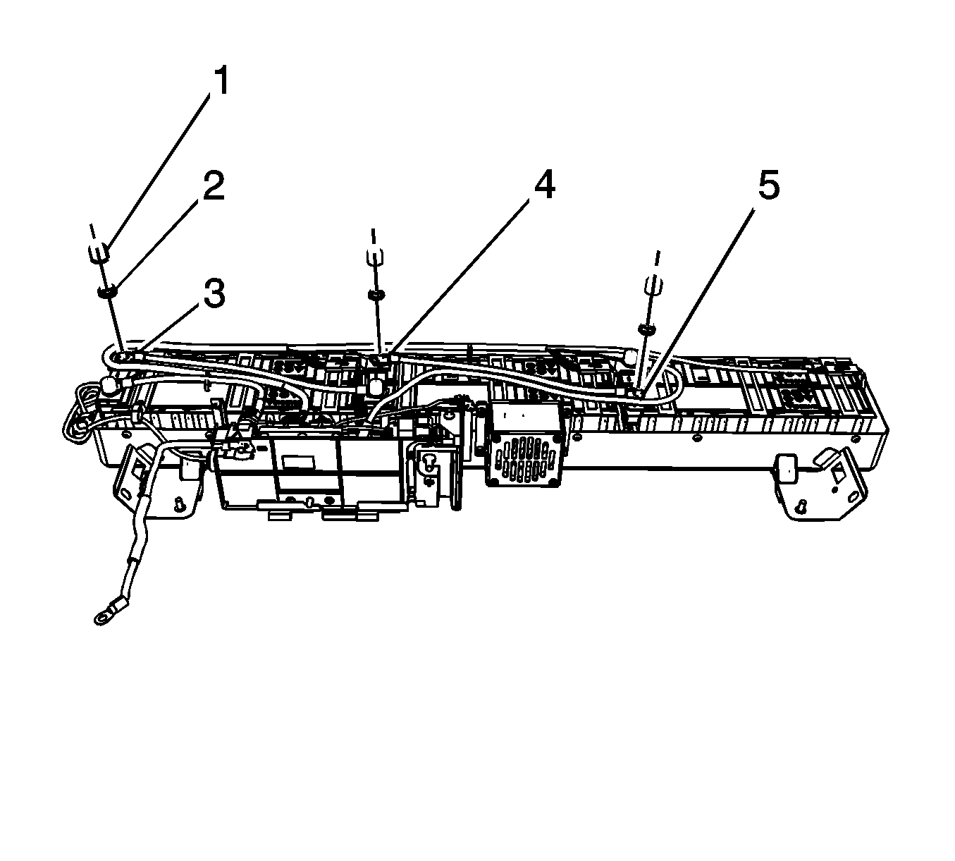
- Remove the generator battery terminal covers (1).
- Remove the generator battery cable nuts (2).
- Remove and reposition the generator battery cable leads (3, 4, 5) from the batteries.
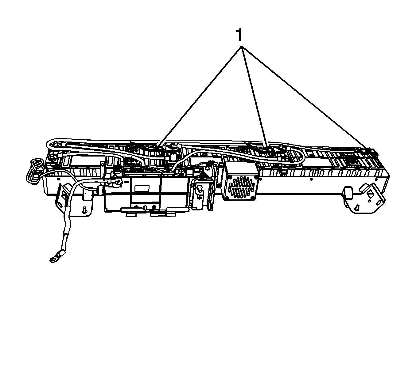
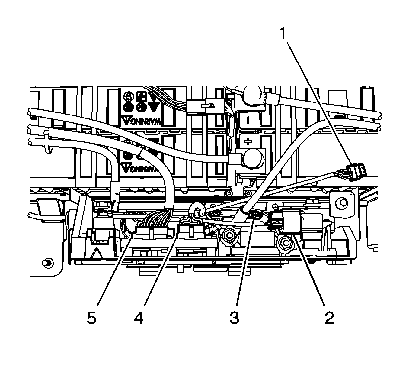
- Disconnect the generator battery temperature sensor wiring harness electrical connectors (1) from the battery temperature sensors.
- Cut the tie straps securing the battery cables to the generator battery temperature sensor wiring harness.
- Disconnect the generator battery temperature sensor wiring harness electrical connectors (2, 5) from the generator control module.
- Remove the generator battery temperature sensor wiring harness.
- Remove the remaining generator battery cable from the battery.
- Remove all the mounting bolts (1) from the 3 generator batteries.
- Remove all 3 generator batteries.
- Remove the 3 temperature sensors from the batteries.
- Remove the four generator battery control module assembly bolts.
- Remove the generator battery control module assembly from the carrier.
- Remove the two remaining lower vent fan bolts and fan from the carrier.
- Clean any corrosion or battery acid that is present on the inside of the hybrid battery case by using a sponge that is lightly dampened with soapy water. It is not necessary to use a neutralizer, such as baking soda.
- Dry the inside of the hybrid battery case using several shop towels.
- Apply black paint to any areas inside of the hybrid battery case where bare metal is present.
- Install the vent fan to the carrier and secure with two lower bolts.
- Install the generator battery control module assembly to the carrier.
- Install the generator battery control module assembly bolts.
- Install the 3 temperature sensors to the new batteries. Polarity does NOT matter.
- Install the new generator batteries.
- Install the generator battery bolts.
- Position and install the generator battery temperature sensor wiring harness.
- Connect the generator battery temperature sensor wiring harness electrical connectors to the battery temperature sensors.
- Connect the generator battery temperature sensor wiring harness electrical connectors to the generator control module.
- Position and install the generator battery cable leads to the battery terminals.
- Install the generator battery cable nuts to the batteries.
- Install the generator battery terminal covers.
- Install NEW tie straps in order to secure the battery cables to the generator battery temperature sensor wiring harness.
- Install the generator battery cover.
- Install the 12 generator battery cover bolts.
- Install the two generator battery fan bolts.
- Carefully install the generator battery carrier to the vehicle.
- Loosely install the generator battery front bolts at the shock towers.
- Connect the generator battery wiring harness electrical connector to the body wiring harness electrical connector.
- Reinstall the left side rear quarter lower trim panel.
- Install the rear seat rear bolts.
- Lift up the rear seat back.
- Tighten the generator battery bolts at the rear shock towers to 10 N·m (89 lb in).
- Install the 36 volt negative battery cable to the body ground stud and reinstall the nut.
- Install the 36 volt positive battery cable lead to the generator battery.
- Install a NEW 36 volt positive battery cable lead nut. Start the nut finger tight, and then torque to the specification given.
- Install the cable shield lead and the nut to the carrier.
- Carefully install the driver and passenger side foam insulators.
- Install the driver and passenger side rear compartment load floor stowage trays.
- Install the driver and passenger side rear compartment load floor stowage tray retainers.
- Install and close the generator battery disconnect control module cover.
- Install the generator battery cover bolt.
- Install the rear compartment closeout panels.
- Connect the 12 volt negative battery cable.
- Reprogram the ECM with the latest calibrations if a P1A5A DTC was stored with the P1A59 DTC.
- After programming, clear any DTC codes that may be present.
Important: Never assume the battery pack is disabled when the generator battery disconnect control module cover is opened.
| 7.1. | Set the voltmeter to DC voltage. |
| 7.2. | Measure the vehicle's 12-volt battery voltage (at 12-volt positive jumper location and negative battery cable). |
| 7.3. | The meter should read greater than +12 volts DC. |
| 8.1. | Measure from the positive (3) stud to the negative stud (2). The voltage should be less than 3 volts. |
| 8.2. | Measure from the positive (3) stud to vehicle chassis ground (1). The voltage should be less than 3 volts. |
| 8.3. | Measure from the negative (2) stud to vehicle chassis ground (1). The voltage should be less than 3 volts. |
| 8.4. | After verifying that there is no voltage present, the vehicle is now safe to work on. |
Important: Removing the interconnect cables will disable the 36 volts within the generator battery control module.
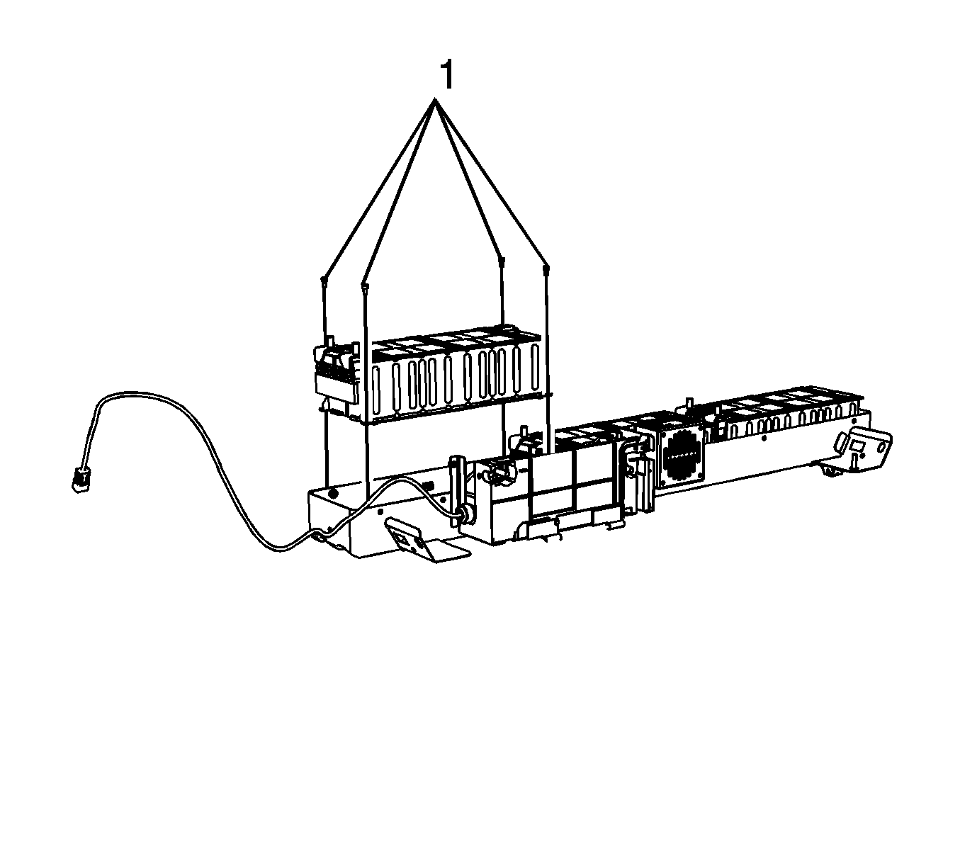
Important: Each failed hybrid battery must be placed in two (double) polyethylene 6 mil bags that were provided with the new batteries. If the bags were not included with the batteries, contact your Saturn Parts Service Analysis (PSA) or the Saturn Saab Service Parts Assistance Centre (SPAC) for Canadian retailers. This double bagging procedure must be performed as soon as the hybrid batteries are removed from the vehicle. After bagging the individual battery cassettes, place the batteries in the original shipping container. After the warranty claim is paid, these parts will be requested to be returned through the GM Warranty Parts Center (WPC) process (Refer to Returning the Battery to the WPC below). Place the WPC request number on the outside of the shipping box. Hybrid battery cassettes are not to be shipped or returned until they are double bagged.
Tighten
Tighten the bolts to 10 N·m (89 lb in).
Important: The cable leads must be installed correctly to prevent low voltage DTCs. It is recommended that the disassembly and reassembly be performed at the same time to ensure reinstalling the cables in the correct location. In the event that the battery cable routing is in question, it is important to remember that the battery cable stud and plate covers up (not visible) the polarity indicator in the plastic case. The polarity that is visible is for the terminal NEXT to the stud. This visible polarity indicator is NOT for the battery stud. This was covered in the BAS hybrid training.
Tighten
Tighten the nuts to 8 N·m (71 lb in).
Tighten
Tighten the bolts to 8 N·m (71 lb in).
Tighten
Tighten the bolts to 8 N·m (71 lb in).
Tighten
Tighten the rear seat rear bolts to 50 N·m (37 lb ft).
Tighten
Tighten the nut to 9 N·m (80 lb in).
Tighten
Tighten the nut to 15 N·m (11 lb ft).
Tighten
Tighten the nut to 9 N·m (80 lb in).
Tighten
Tighten the bolt to 10 N·m (89 lb in).
Service Procedure (AURA)
Important: Dust may be an irritant to skin and eyes. Avoid skin and eye contact. If battery dust is present, remove carefully to avoid inhalation. Wear safety glasses and butyl rubber, natural rubber, neoprene, nitrile or Tyvek protective gloves when handling any corroded hybrid batteries and when cleaning the inside of the hybrid battery case. Discard the gloves after each use and dispose of any corrosion material that was removed from the case.
- Remove the ignition key from the ignition switch. Secure the ignition key in order to ensure that the key CANNOT be re-installed without your knowledge.
- Disconnect the 12 volt negative battery cable.
- Fold down both rear seat backs.
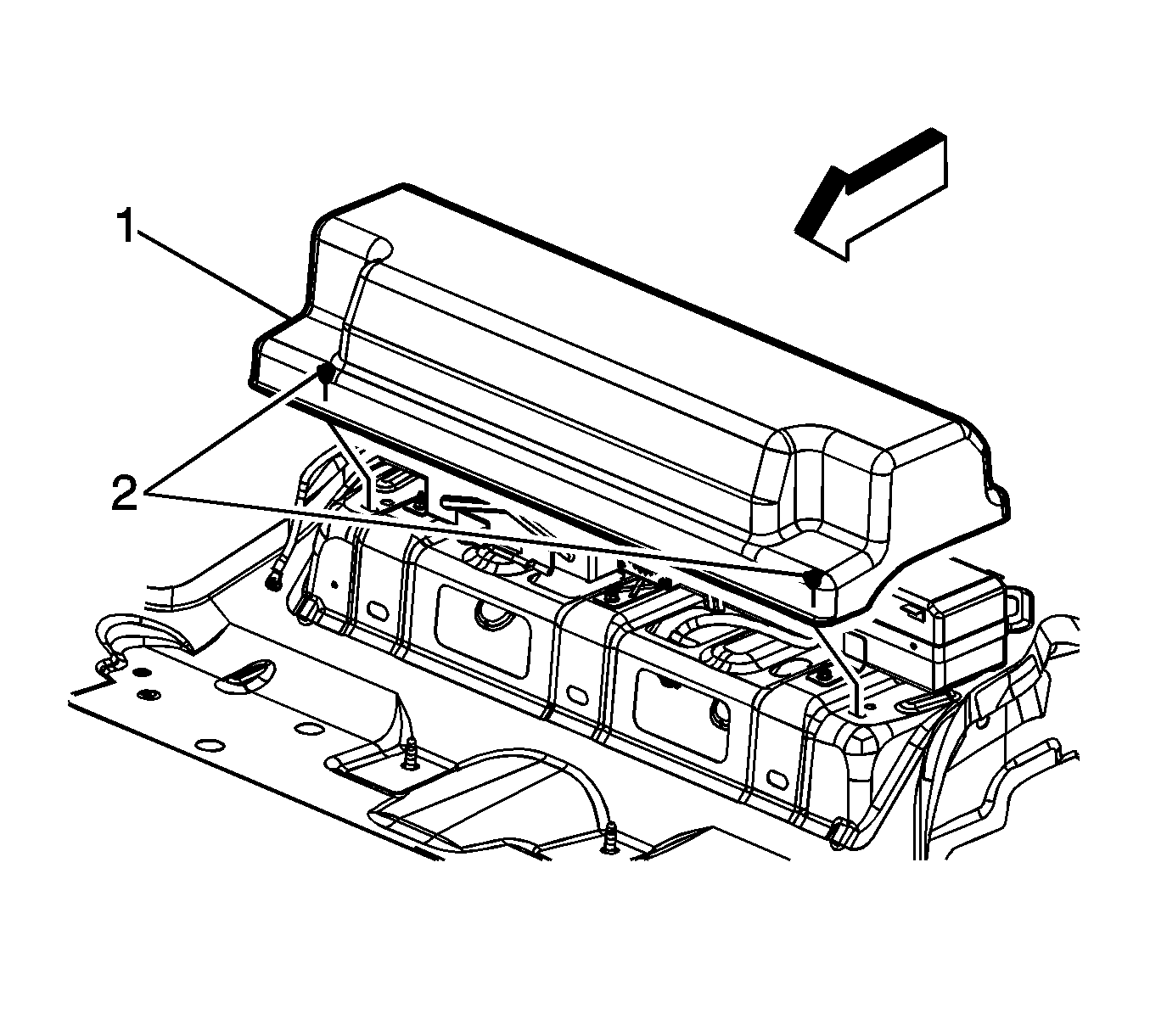
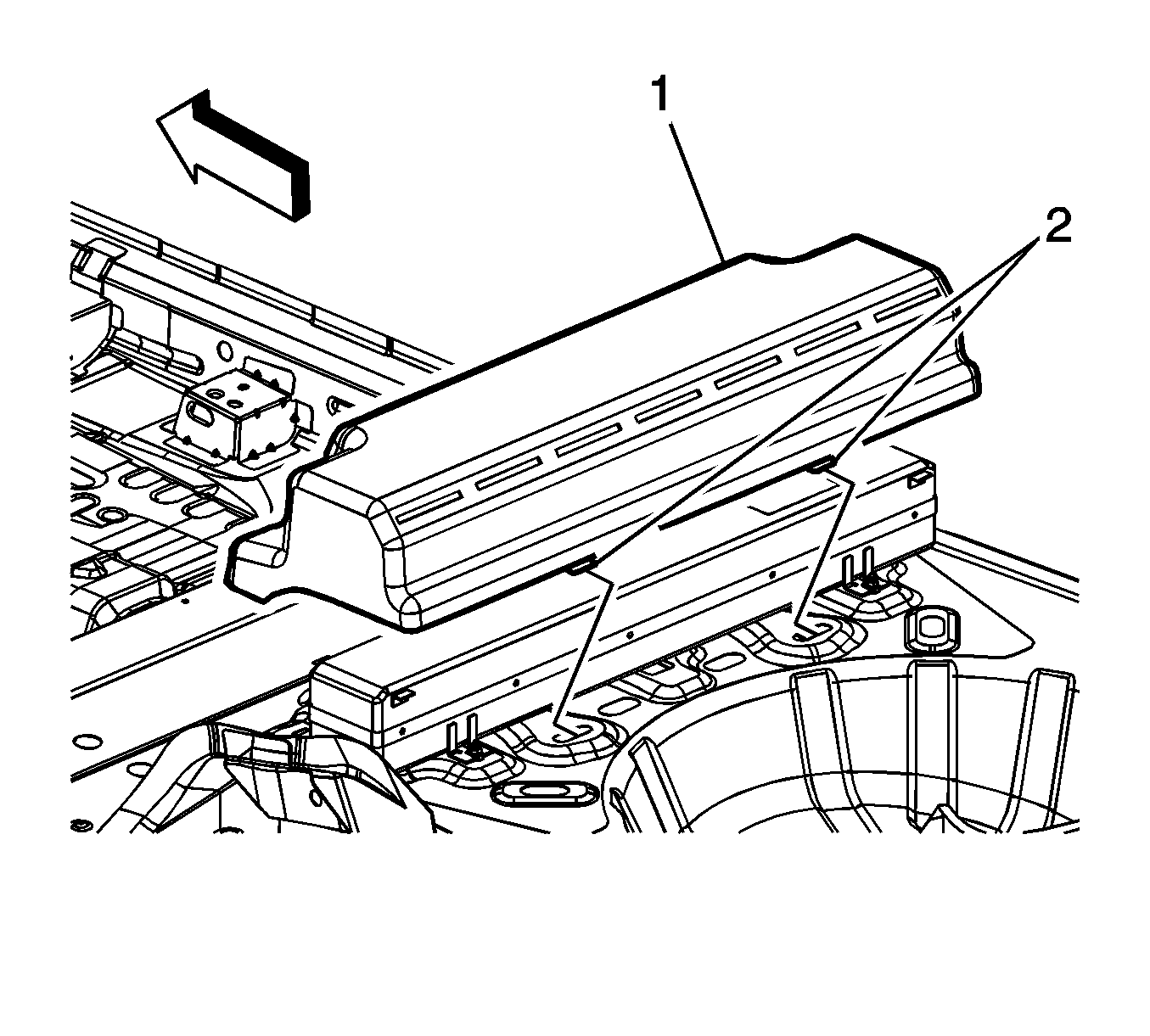
- Carefully lift up on the load floor rear compartment cover (1) at the retaining clip (2) locations.
- Tilt the load floor rear compartment cover (2) towards the rear of the vehicle slightly, disengaging the tabs (1) and remove the load floor rear compartment cover.
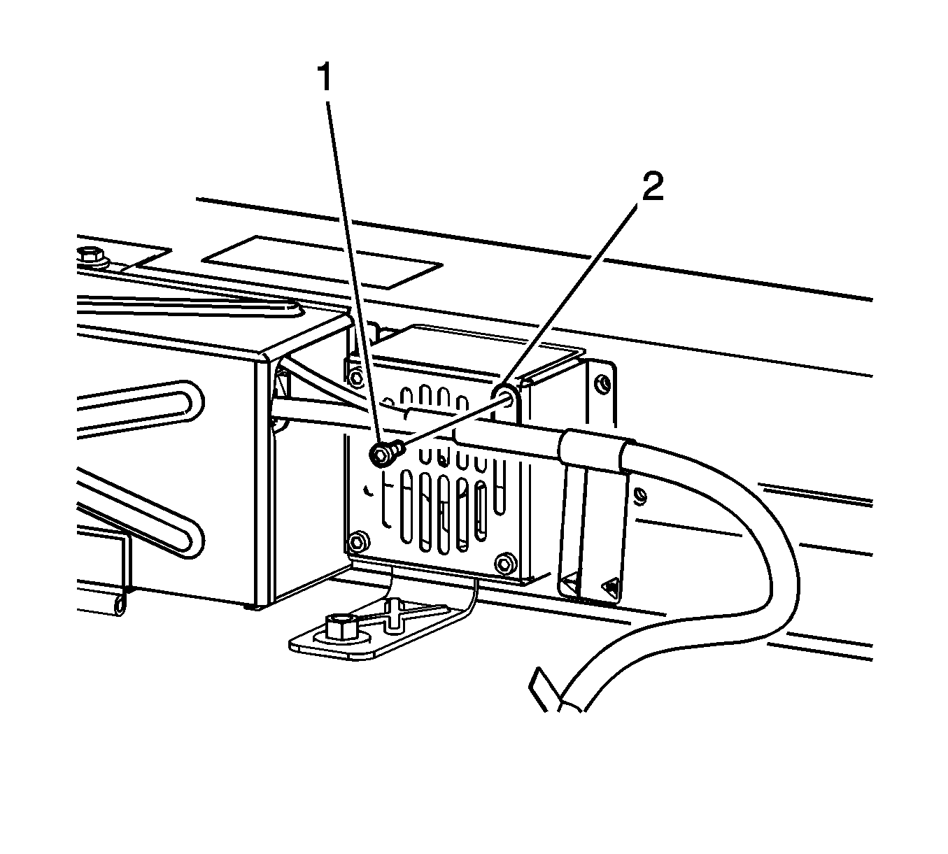
- Remove the generator battery disconnect control module cover bolt .
- Slide the generator battery disconnect control module cover to the right and remove the cover.
- WAIT at least 5 minutes in order to allow the generator control module capacitors to discharge.
- The generator battery will have to be checked for voltage potential using a voltmeter. First, verify that the voltmeter works.
- Now, check the generator battery for voltage potential in order to ensure that the generator battery has been disabled.
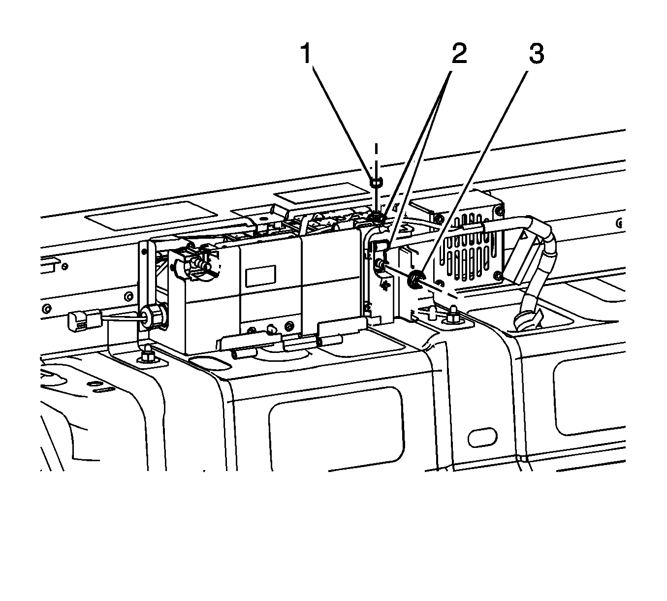
- Remove the 36-volt negative battery cable ground nut (1).
- Remove the 36-volt positive battery cable retainer bolt (1).
- Remove and discard the 36-volt positive battery cable lead nut (3).
- Remove the 36-volt positive battery cable lead nut (1).
- Remove the 36-volt positive battery cable leads (2).
- Secure the cables out of the way, ensuring that the cables CANNOT be re-installed without your knowledge.
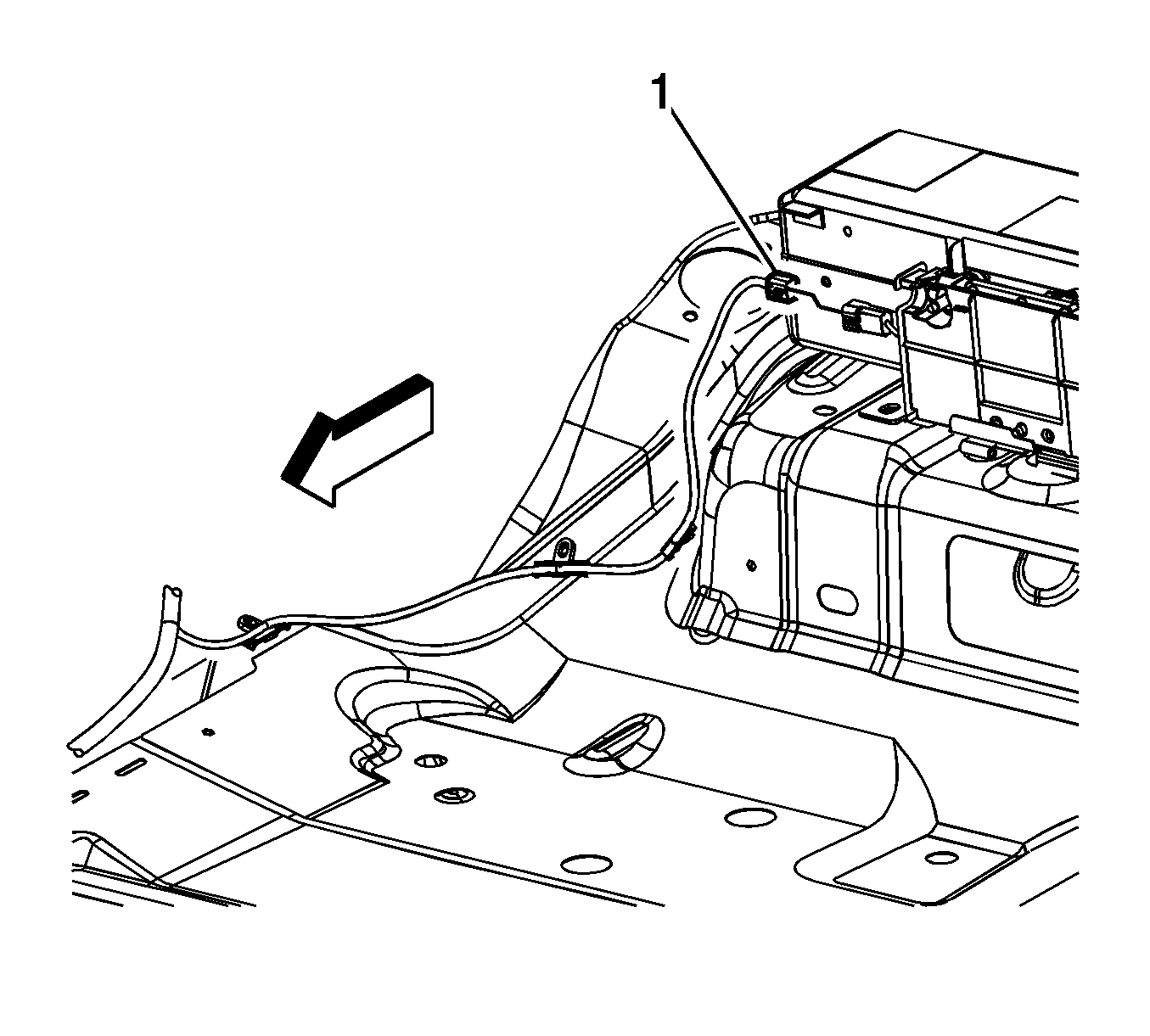
- Disconnect the body wiring harness electrical connector (1) from the generator battery disconnect control module pigtail.
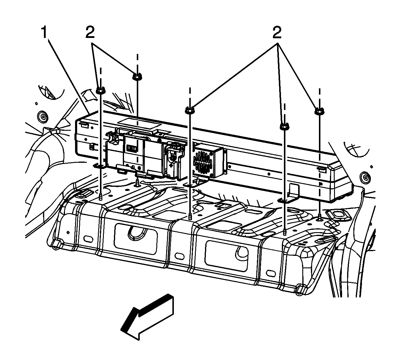
- Remove the generator battery carrier nuts (2).
- With the aid of an assistant, lift the generator battery carrier up off of the studs, and rotate and position the carrier towards the rear of the vehicle.
- With the aid of an assistant, remove the generator battery carrier out though the truck opening. Place the carrier on a workbench.
- Remove the two upper generator battery fan bolts (2).
- Remove the 12 generator battery cover bolts (1).
- Remove the generator battery wiring harness from the clip (3) on the generator battery cover.
- Remove the generator battery cover.
- Remove the generator battery terminal covers (1).
- Remove the generator battery cable nuts (2).
- Remove and reposition the generator battery cable leads (3, 4, 5) from the batteries.
- Disconnect the generator battery temperature sensor wiring harness electrical connectors (1) from the battery temperature sensors.
- Cut the tie straps securing the battery cables to the generator battery temperature sensor wiring harness.
- Disconnect the generator battery temperature sensor wiring harness electrical connectors (2, 5) from the generator control module.
- Remove the generator battery temperature sensor wiring harness.
- Remove the remaining generator battery cable from the battery.
- Remove all the mounting bolts (1) from the 3 generator batteries.
- Remove all 3 generator batteries.
- Remove the 3 temperature sensors from the batteries.
- Remove the four generator battery control module assembly bolts.
- Remove the generator battery control module assembly from the carrier.
- Remove the two remaining lower vent fan bolts and fan from carrier.
- Clean any corrosion or battery acid that is present on the inside of the hybrid battery case by using a sponge that is lightly dampened with soapy water. It is not necessary to use a neutralizer, such as baking soda.
- Dry the inside of the hybrid battery case using several shop towels.
- Apply black paint to any areas inside of the hybrid battery case where bare metal is present.
- Install the vent fan to the carrier and secure with two lower bolts.
- Install the generator battery control module assembly to the carrier.
- Install the generator battery control module assembly bolts.
- Install the 3 temperature sensors to the new batteries. Polarity does NOT matter.
- Install the new generator batteries.
- Install the generator battery bolts.
- Position and install the generator battery temperature sensor wiring harness.
- Connect the generator battery temperature sensor wiring harness electrical connectors to the battery temperature sensors.
- Connect the generator battery temperature sensor wiring harness electrical connectors to the generator control module.
- Position and install the generator battery cable leads to the battery terminals.
- Install the generator battery cable nuts to the batteries.
- Install the generator battery terminal covers.
- Install NEW tie straps in order to secure the battery cables to the generator battery temperature sensor wiring harness.
- Install the generator battery cover.
- Install the 12 generator battery cover bolts.
- Install the two generator battery fan bolts.
- With the aid of an assistant, install the generator battery carrier in though the truck opening and rotate and position the carrier towards the front of the vehicle.
- With the aid of an assistant, lift the generator battery carrier up onto the studs.
- Install the generator battery carrier nuts.
- Connect the body wiring harness electrical connector to the generator battery disconnect control module pigtail.
- Install the 36-volt positive battery cable leads.
- Install the 36-volt positive battery cable lead nut.
- Install a NEW 36-volt positive battery cable lead nut. Start the nut finger tight, and then torque to the specification given.
- Position the 36-volt positive battery cable retainer to the fan cover.
- Install the 36-volt positive battery cable retainer bolt.
- Install the 36-volt negative battery cable ground nut.
- Install the generator battery cover bolt.
- Tilt the load floor rear compartment cover towards the rear of the vehicle slightly in order to insert the tabs into the battery tray rear support.
- Set the load floor rear compartment cover down ensuring that the retaining clips align to the proper locations, carefully push down securing the cover.
- Return both rear seats backs to their proper positions.
- Connect the 12 volt negative battery cable.
- Reprogram the ECM with the latest calibrations if a P1A5A DTC was stored with the P1A59 DTC.
- After programming, clear any DTC codes that may be present.


Important: Never assume the battery pack is disabled when the generator battery disconnect control module cover is opened.
| 9.1. | Set the voltmeter to DC voltage. |
| 9.2. | Measure the vehicle's 12-volt battery voltage (at 12-volt positive jumper location and negative battery cable). |
| 9.3. | The meter should read greater than +12 volts DC. |
| 10.1. | Measure from the positive (3) stud to the negative stud (2). The voltage should be less than 3 volts. |
| 10.2. | Measure from the positive (3) stud to vehicle chassis ground (1). The voltage should be less than 3 volts. |
| 10.3. | Measure from the negative (2) stud to vehicle chassis ground (1). The voltage should be less than 3 volts. |
| 10.4. | After verifying that there is no voltage present, the vehicle is now safe to work on. |
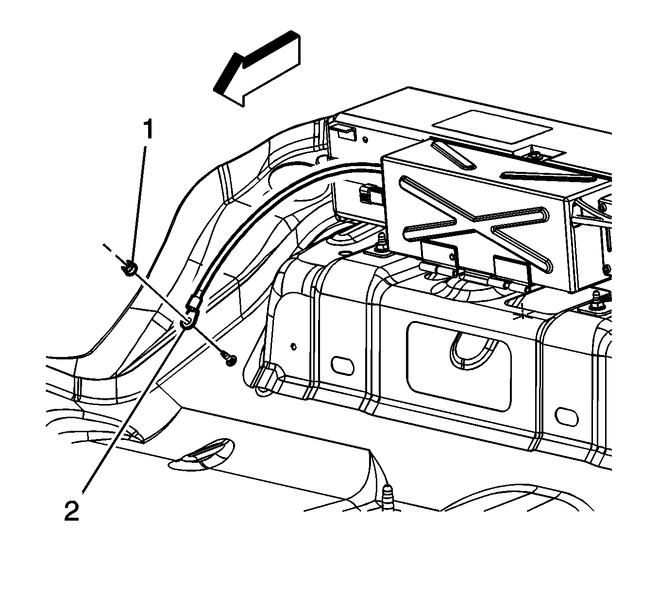


Important: Removing the interconnect cables will disable the 36 volts within the generator battery control module.


Important: Each failed hybrid battery must be placed in two (double) polyethylene 6 mil bags that were provided with the new batteries. If the bags were not included with the batteries, contact your Saturn Parts Service Analysis (PSA) or the Saturn Saab Service Parts Assistance Centre (SPAC) for Canadian retailers. This double bagging procedure must be performed as soon as the hybrid batteries are removed from the vehicle. After bagging the individual battery cassettes, place the batteries in the original shipping container. After the warranty claim is paid, these parts will be requested to be returned through the GM Warranty Parts Center (WPC) process (Refer to Returning the Battery to the WPC below). Place the WPC request number on the outside of the shipping box. Hybrid battery cassettes are not to be shipped or returned until they are double bagged.
Tighten
Tighten the bolts to 10 N·m (89 lb in).
Important: The cable leads must be installed correctly to prevent low voltage DTCs. It is recommended that the disassembly and reassembly be performed at the same time to ensure reinstalling the cables in the correct location. In the event that the battery cable routing is in question, it is important to remember that the battery cable stud and plate covers up (not visible) the polarity indicator in the plastic case. The polarity that is visible is for the terminal NEXT to the stud. This visible polarity indicator is NOT for the battery stud. This was covered in the BAS hybrid training.
Tighten
Tighten the nuts to 8 N·m (71 lb in).
Tighten
Tighten the bolts to 8 N·m (71 lb in).
Tighten
Tighten the bolts to 8 N·m (71 lb in).
Tighten
Tighten the nuts to 25 N·m (18 lb ft).
Tighten
Tighten the nut to 9 N·m (18 lb in).
Tighten
Tighten the nut to 15 N·m (11 lb ft).
Tighten
Tighten the bolt to 8 N·m (71 lb in).
Tighten
Tighten the nut to 9 N·m (80 lb in).
Tighten
Tighten the bolt to 10 N·m (89 lb in).
If the hybrid battery case can not be cleaned by following the above procedure due to extensive damage to the battery mounting structure (bolt attachments), replace the complete hybrid battery assembly, which includes the case, 3 cassettes, BECM, and battery disconnect unit.
Important: Hybrid parts are no longer on restriction through TAC. All hybrid parts can now be ordered through your parts department.
Important: For U.S. Dealers: Hybrid Battery Cassette replacement was recently covered in the October Emerging Issues Seminar (10207.10D). An archived copy of this training seminar should be stored on your Genesis IDL Box. It will also be available on the GM Training Website (www.gmtraining.com) by the end of November 2007. This training seminar highlights BDU and Hybrid Battery Cassette replacement. Once this video is loaded to the GM Training Website and you log in, you will be able to take the following path to locate and view the October Emerging Issues Seminar (10207.10D):
- Click the Service Know-How/ TECHAssist Hyper-link on the left side of the screen.
- Click the Emerging Issues Hyper-link in the center of the screen.
- Click the Searchable Streaming Video Hyperlink in the center of the screen.
- Enter the course number 10207.10D in the search box on the left side of the screen and click Search.
Returning the Battery to the WPC
Hybrid parts will be returned through the Warranty Part Center (WPC) by request using the Saturn Failed Parts Return System. For additional information on the parts return process, reference the latest version of Corporate Bulletin Number 05-00-89-042C - Warranty Parts Center/Saturn Parts Return Program (U.S. Only). Canadian retailers should refer to Service Bulletin 99-00-89-019E for all Warranty Parts Center returns. Do NOT return parts to the WPC without a WPC request. If a WPC part return request is not issued when the warranty claim is paid, please contact the WPC.
Package the part to be returned in the same container that was used to deliver the replacement part. This container has specific labeling for a Class 8 hazardous materials that are exempt from a hazardous material classification for the purposes of transportation.
Use the UPS-ARS label to ship via UPS as explained in the bulletins referenced above.
Parts Information
Part Number | Description |
|---|---|
25964892 | Battery, Generator (Battery Only w/3 Cassettes and Hardware) |
11609746 | Nut, Battery Positive Cable (36V) |
Warranty Information
For vehicles repaired under warranty, use:
Labor Operation | Description | Labor Time |
|---|---|---|
N9582 (AURA)* | Hybrid Battery Corrosion Repair (Replace Batteries, Clean Case and Reprogram ECM) | 2.2 hrs |
N9582 (VUE)* | Hybrid Battery Corrosion Repair (Replace Batteries, Clean Case and Reprogram ECM) | 2.4 hrs |
* This labor operation number is for bulletin use only. This number will not be published in the Labor Time Guide. | ||
