Circuit Description
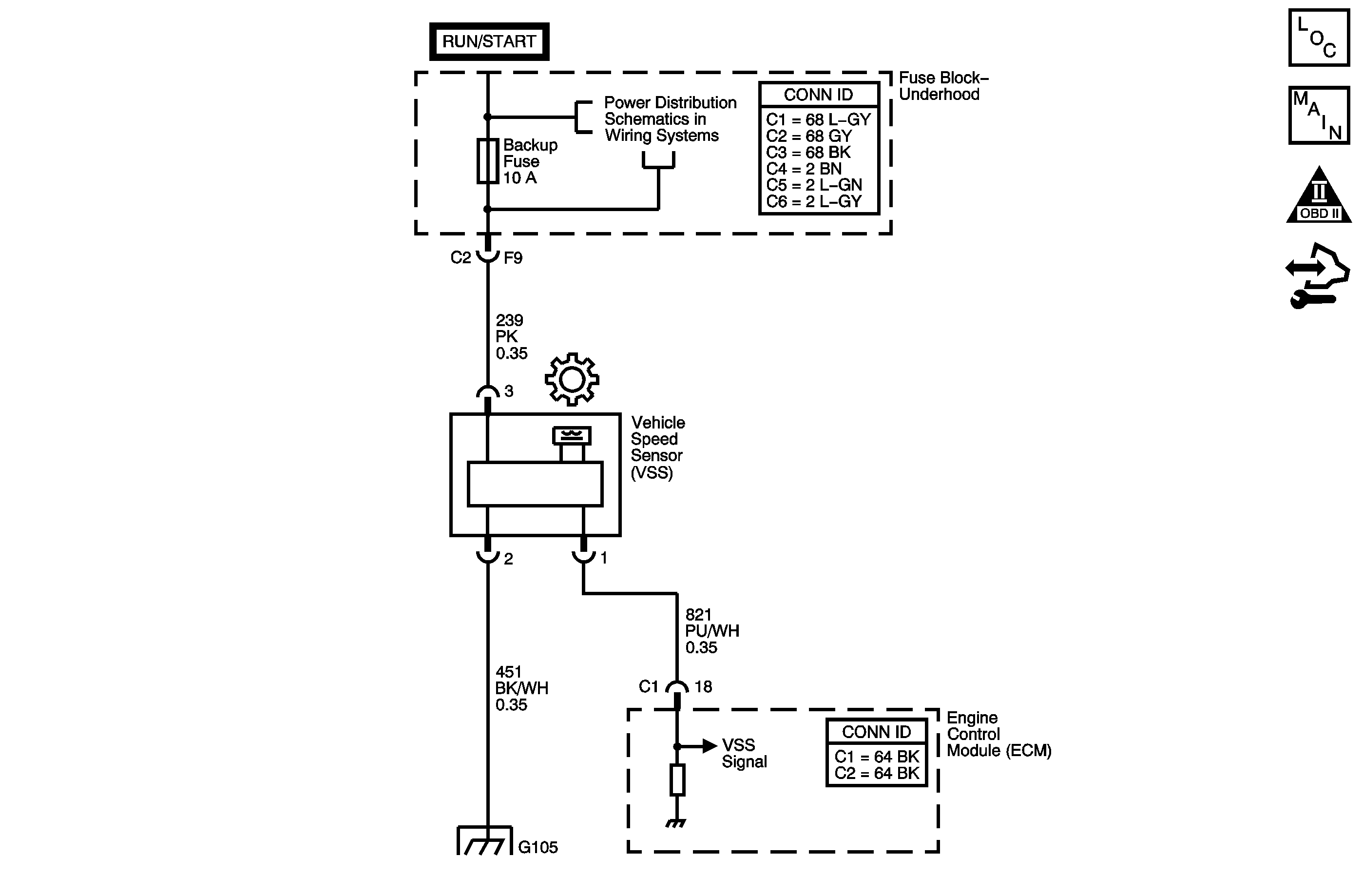
Vehicle speed information is provided to the engine control module (ECM) by the vehicle speed sensor (VSS). The Hall-Effect sensor contains a permanent magnet and a semiconductor plate to which ignition voltage is applied. As the output shaft spins, the rotor directs the field of the permanent magnet either toward or away from the plate. When the ignition is ON and the magnetic field is directed away from the plate, electrons are evenly distributed across the plate. When the rotor directs the field toward the plate, the electrons are redistributed unevenly across the front and back of the plate. The uneven distribution causes a voltage to be produced across the plate. The VSS produces a frequency signal that is proportional to vehicle speed. The ECM converts the VSS signal to vehicle speed, displayed on the scan tool in miles per hour and kilometers per hour. The ECM also uses the VSS signal to generate the 4,000 pulses per mile vehicle speed signal used by the instrument cluster.
When the ECM detects a very low vehicle speed, while the vehicle is in motion, DTC P0502 sets. DTC P0502 is a type B DTC.
DTC Descriptor
This diagnostic procedure supports the following DTC:
DTC P0502 Vehicle Speed Sensor (VSS) Circuit Low Voltage
Conditions for Running the DTC
| • | Engine speed is 1,700-3,600 RPM. |
| • | The TP angle is between 2-23 percent. |
| • | The MAP sensor is 60-80 kPa (9-12 psi). |
Conditions for Setting the DTC
The VSS indicates a speed of less than 3 km/h (2 mph) for a total of 6 seconds.
Action Taken When the DTC Sets
| • | The ECM illuminates the malfunction indicator lamp (MIL) during the second consecutive trip in which the Conditions for Setting the DTC are met. |
| • | The ECM disables Cruise Control. |
| • | The ECM records the operating conditions when the Conditions for Setting the DTC are met. The ECM stores this information as Freeze Frame and Failure Records. |
| • | The ECM stores DTC P0502 in ECM history during the second consecutive trip in which the Conditions for Setting the DTC are met. |
Conditions for Clearing the MIL/DTC
| • | The ECM turns OFF the MIL during the third consecutive trip in which the diagnostic runs and passes. |
| • | A scan tool can clear the MIL/DTC. |
| • | The ECM clears the DTC from ECM history if the vehicle completes 40 warm-up cycles without an emission-related diagnostic fault occurring. |
| • | The ECM cancels the DTC default actions when the ignition switch is OFF long enough in order to power down the ECM. |
Step | Action | Value(s) | Yes | No | ||||||||||||
|---|---|---|---|---|---|---|---|---|---|---|---|---|---|---|---|---|
1 | Did you perform the Diagnostic System Check - Vehicle? | -- | Go to Step 2 | |||||||||||||
2 |
Important: Before clearing the DTCs, use the scan tool in order to record the Freeze Frame and Failure Records for reference. The Clear Info function will erase the data. Notice: Support the lower control arms in the normal horizontal position in order to avoid damage to the drive axles. Do not operate the vehicle in gear with the wheels hanging down at full travel. Does the scan tool indicate Vehicle Speed increasing when wheel speed increases? | -- | Refer to Testing for Intermittent Conditions and Poor Connections | Go to Step 3 | ||||||||||||
3 |
Does the voltage measure near the specified value? | B+ | Go to Step 4 | Go to Step 9 | ||||||||||||
4 | Measure the voltage from the ignition 1 voltage circuit of the VSS to the VSS ground circuit. Does the voltage measure near the specified value? | B+ | Go to Step 5 | Go to Step 12 | ||||||||||||
5 |
Does the DMM display AC volts above the specified value? | 0.15 V | Go to Step 6 | Go to Step 16 | ||||||||||||
6 |
Does the resistance measure less than the specified value? | 5 ohms | Go to Step 7 | Go to Step 13 | ||||||||||||
7 | Using the DMM, measure the resistance between the VSS signal circuit and ground. Is the resistance less than the specified value? | 50 kohms | Go to Step 14 | Go to Step 8 | ||||||||||||
8 | Using a test lamp connected to the ground, probe the VSS signal circuit. Does the test lamp illuminate? | -- | Go to Step 15 | Go to Step 18 | ||||||||||||
9 |
Was the fuse open? | -- | Go to Step 10 | Go to Step 11 | ||||||||||||
10 |
Important: The condition that affects this circuit may exist in other connecting branches of the circuit. Refer to Power Distribution Schematics for complete circuit distribution. Test the ignition 1 voltage circuit of the VSS for a short to ground. Refer to Testing for Short to Ground . Did you find and correct the condition? | -- | Go to Step 19 | -- | ||||||||||||
11 | Test for an open or high resistance in the ignition 1 voltage circuit of the VSS. Refer to Testing for Continuity . Did you find and correct the condition? | -- | Go to Step 19 | -- | ||||||||||||
12 | Repair the open in the VSS ground circuit. Refer to Wiring Repairs . Did you complete the repair? | -- | Go to Step 19 | -- | ||||||||||||
13 | Repair the open in the VSS signal circuit. Refer to Wiring Repairs . Did you complete the repair? | -- | Go to Step 19 | -- | ||||||||||||
14 | Repair the short to ground in the VSS signal circuit. Refer to Wiring Repairs . Did you complete the repair? | -- | Go to Step 19 | -- | ||||||||||||
15 | Repair the short to voltage on the VSS signal circuit. Refer to Wiring Repairs . Did you complete the repair? | -- | Go to Step 19 | -- | ||||||||||||
16 |
Did you find and correct the condition? | -- | Go to Step 19 | Go to Step 17 | ||||||||||||
17 | Replace the VSS. Refer to Vehicle Speed Sensor Replacement . Did you complete the repair? | -- | Go to Step 19 | -- | ||||||||||||
18 | Replace the ECM. Refer to Control Module References for replacement, setup, and programming. Did you complete the repair? | -- | Go to Step 19 | -- | ||||||||||||
19 | In order to verify your repair, perform the following procedure:
Has the test run and passed? | -- | Go to Step 20 | Go to Step 2 | ||||||||||||
20 | With a scan tool observe the stored information, capture info and DTC Info. Does the scan tool display any DTCs that you have not diagnosed? | -- | System OK |
