Intake Manifold Replacement LAT
Removal Procedure
- Remove the air cleaner outlet duct. Refer to Air Cleaner Outlet Duct Replacement .
- Remove the radiator inlet hose. Refer to Radiator Inlet Hose Replacement .
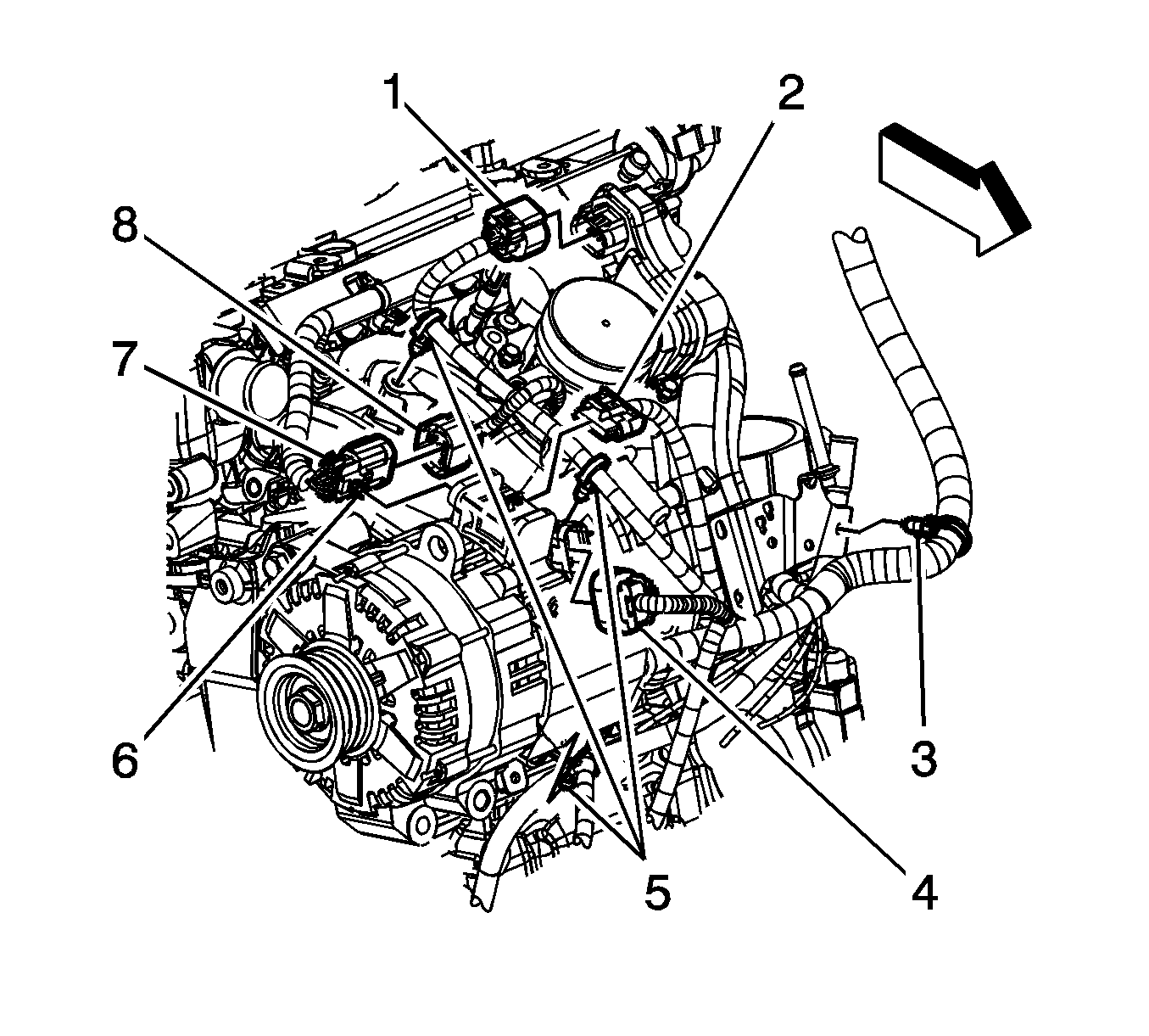
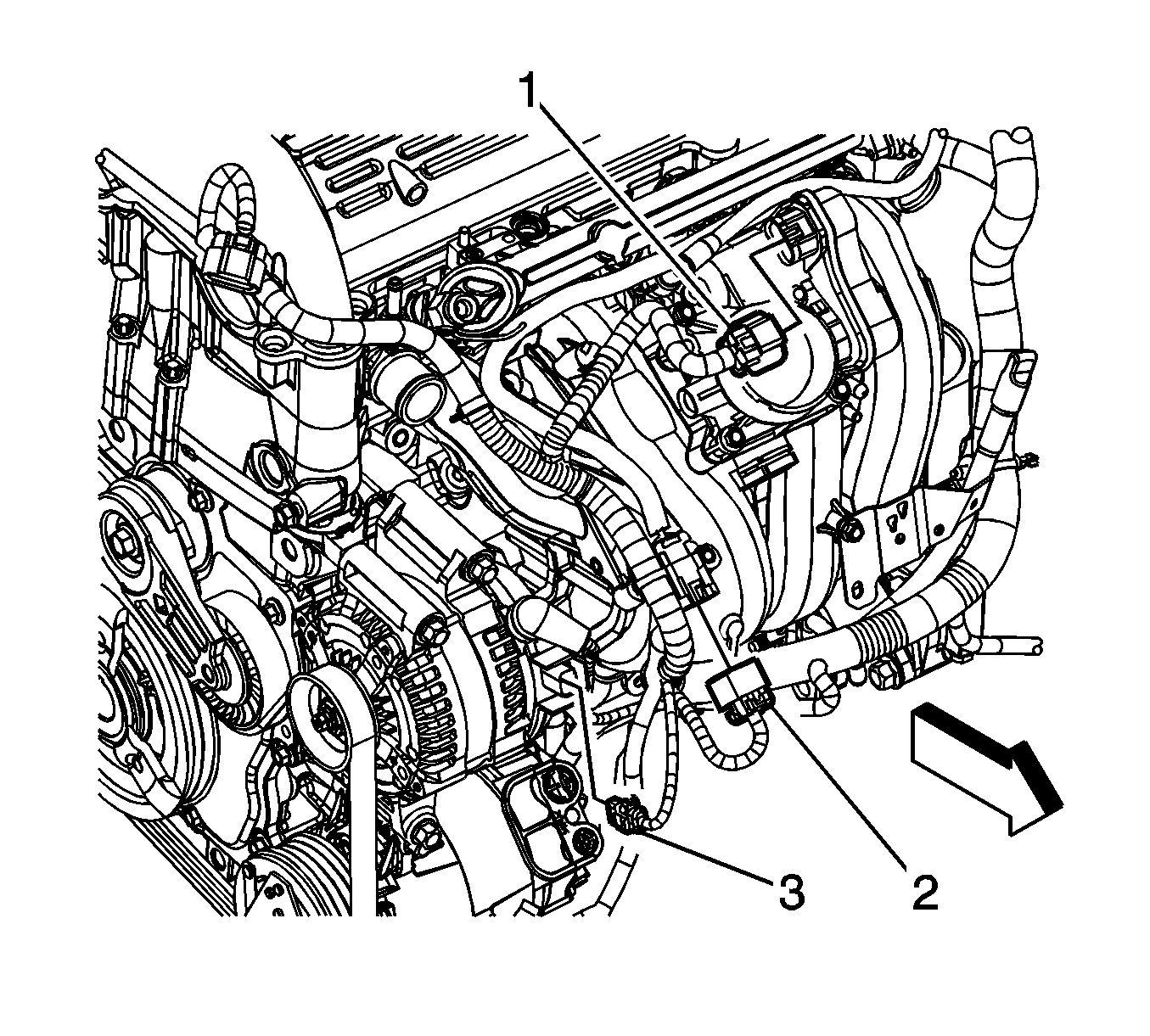
- Disconnect the engine wiring harness electrical connector (1) from the throttle actuator control (TAC).
- Disconnect the engine wiring harness electrical connector (2) from the generator starter.
- Disconnect the engine wiring harness electrical connector (4) from the generator starter.
- Remove the fuel injector wiring harness electrical connector retainer (6) from the generator starter.
- Disconnect the fuel injector wiring harness electrical connector (7) from the engine wiring harness electrical connector (8).
- Remove the engine wiring harness clips (5) from the intake manifold.
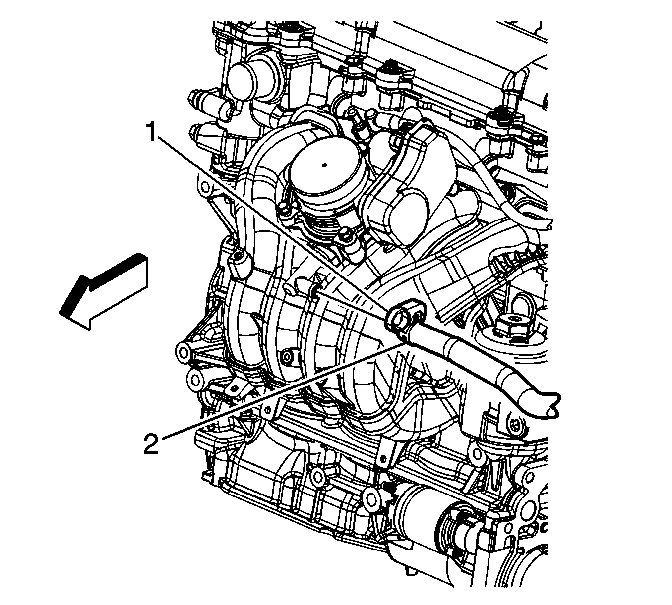
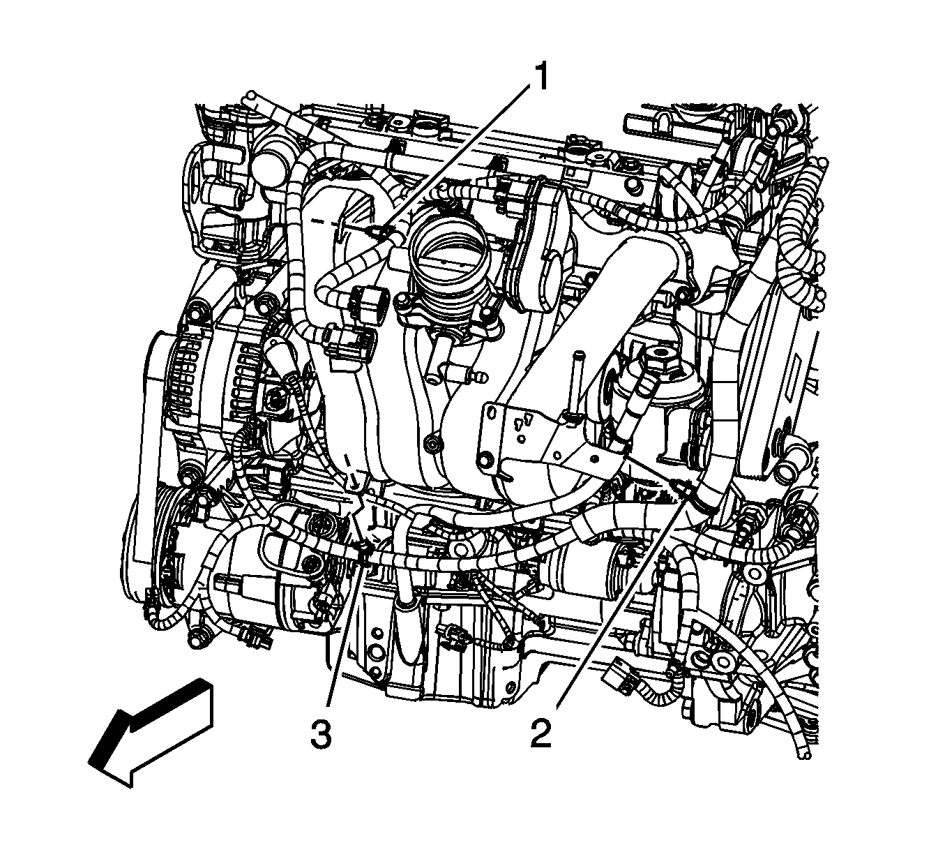
- Reposition the vacuum brake booster hose clamp (1) at the intake manifold.
- Remove the vacuum brake booster hose (2) from the intake manifold.
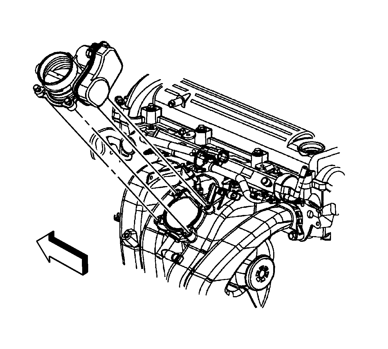
- Remove the throttle body bolts.
- Remove the throttle body and seal.
- Remove and inspect the throttle body seal.
- Disconnect the engine wiring harness electrical connector from the manifold absolute pressure (MAP) sensor.
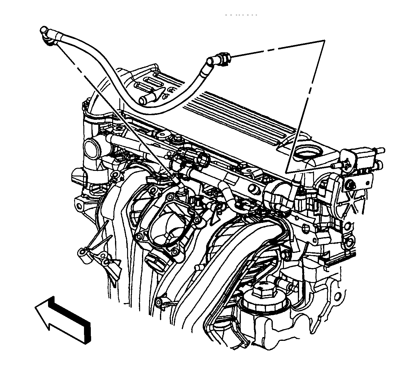
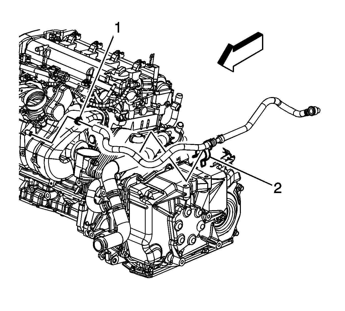
- Disconnect the evaporative emission (EVAP) canister purge tube from the intake manifold and the EVAP solenoid. Refer to Plastic Collar Quick Connect Fitting Service .
- Remove the oil level indicator tube. Refer to Oil Level Indicator and Tube Replacement .
- Remove the fuel rail. Refer to Fuel Injection Fuel Rail Assembly Replacement .
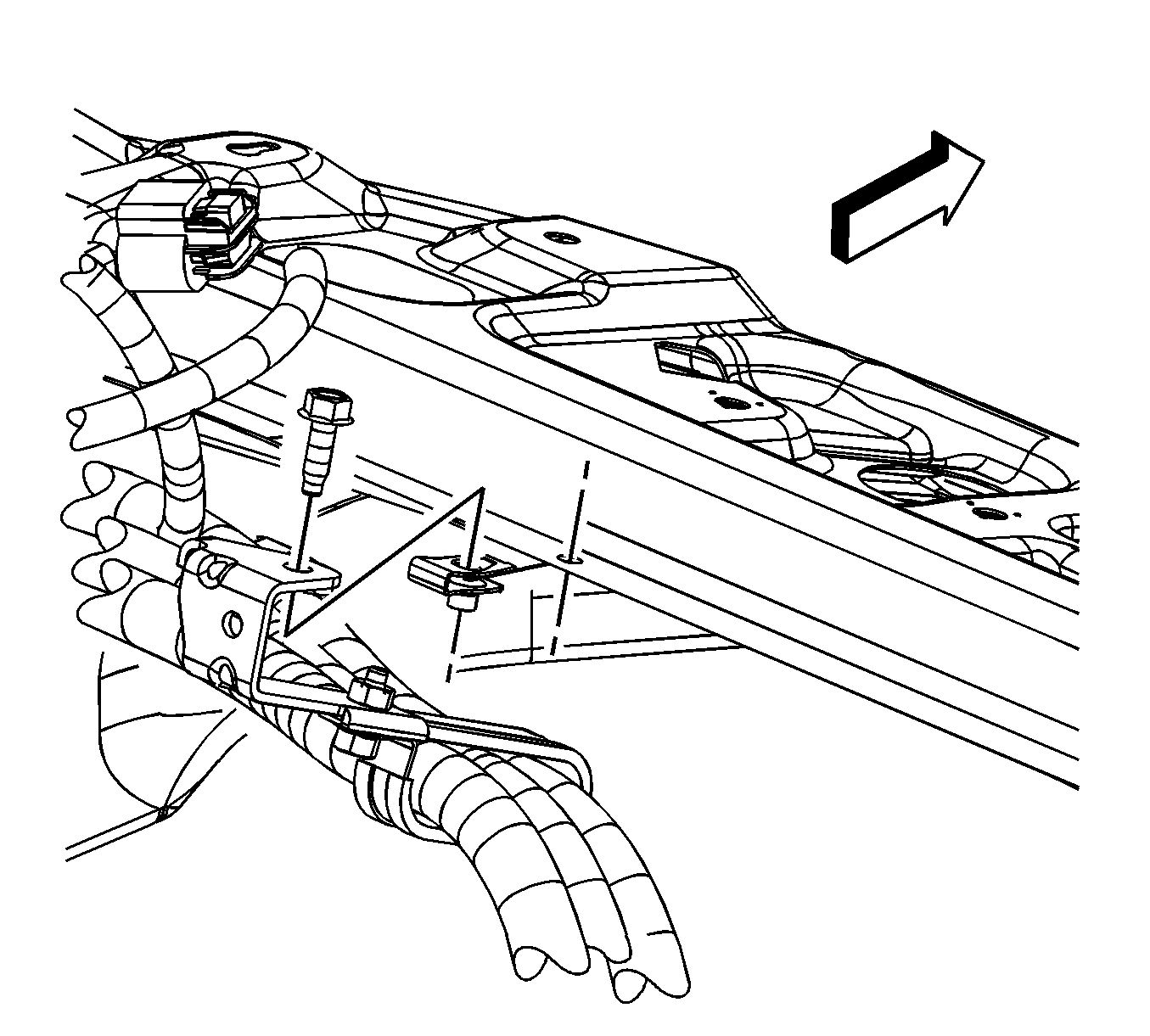
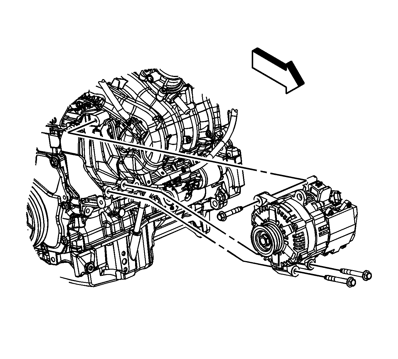
- Remove the 3-phase voltage cable bracket bolt at the tie bar.
- Remove the generator starter bolts.
- Reposition and secure the generator starter out of the way.
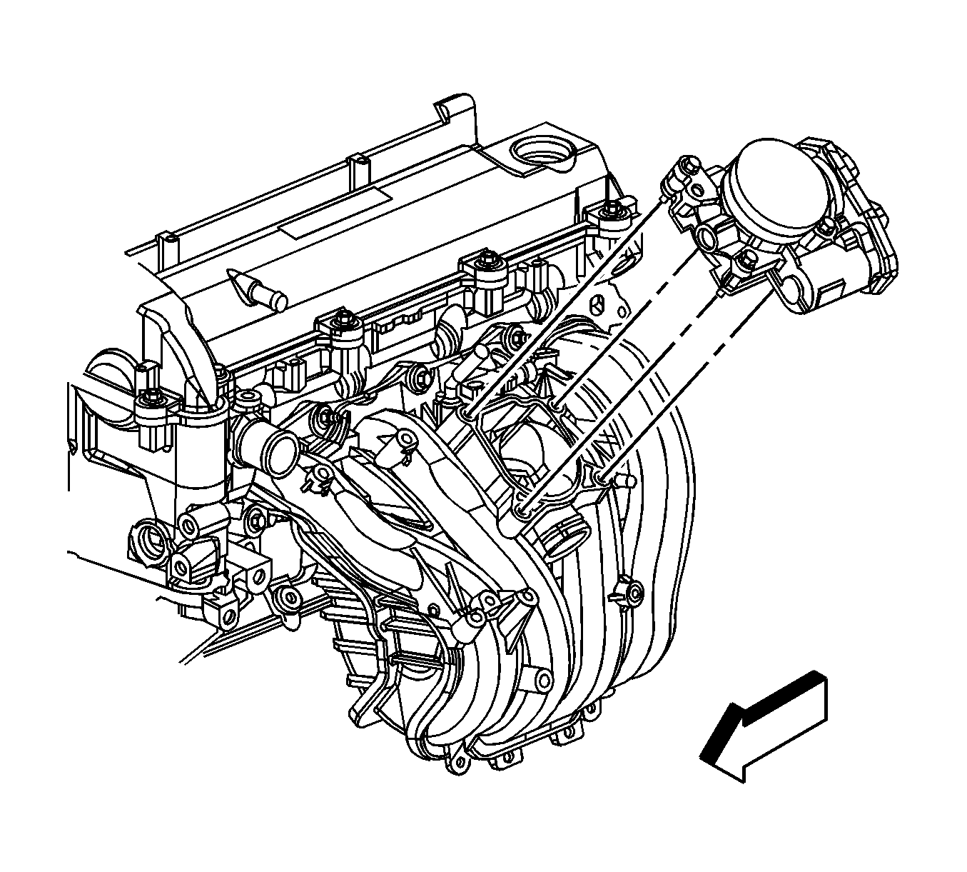
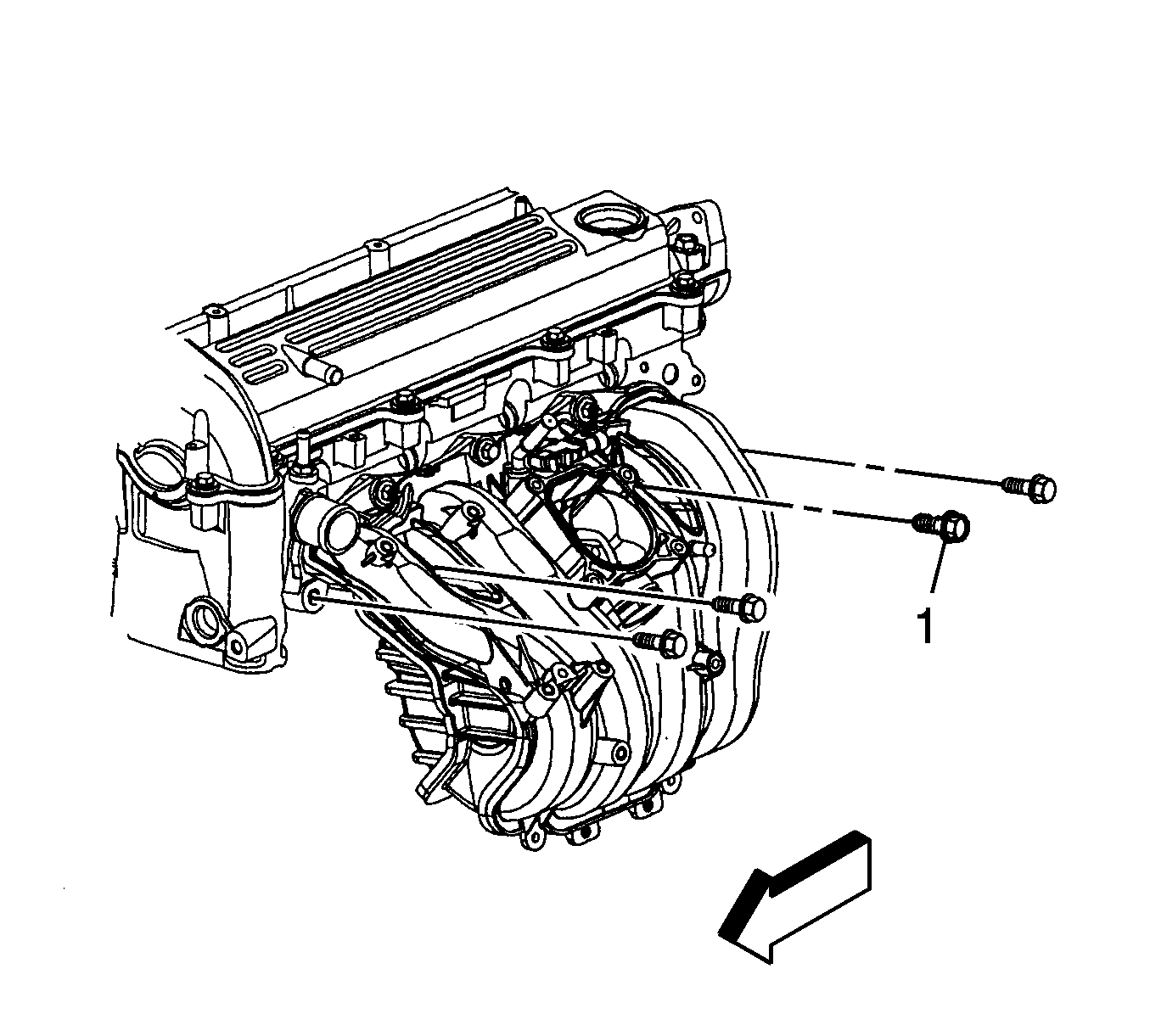
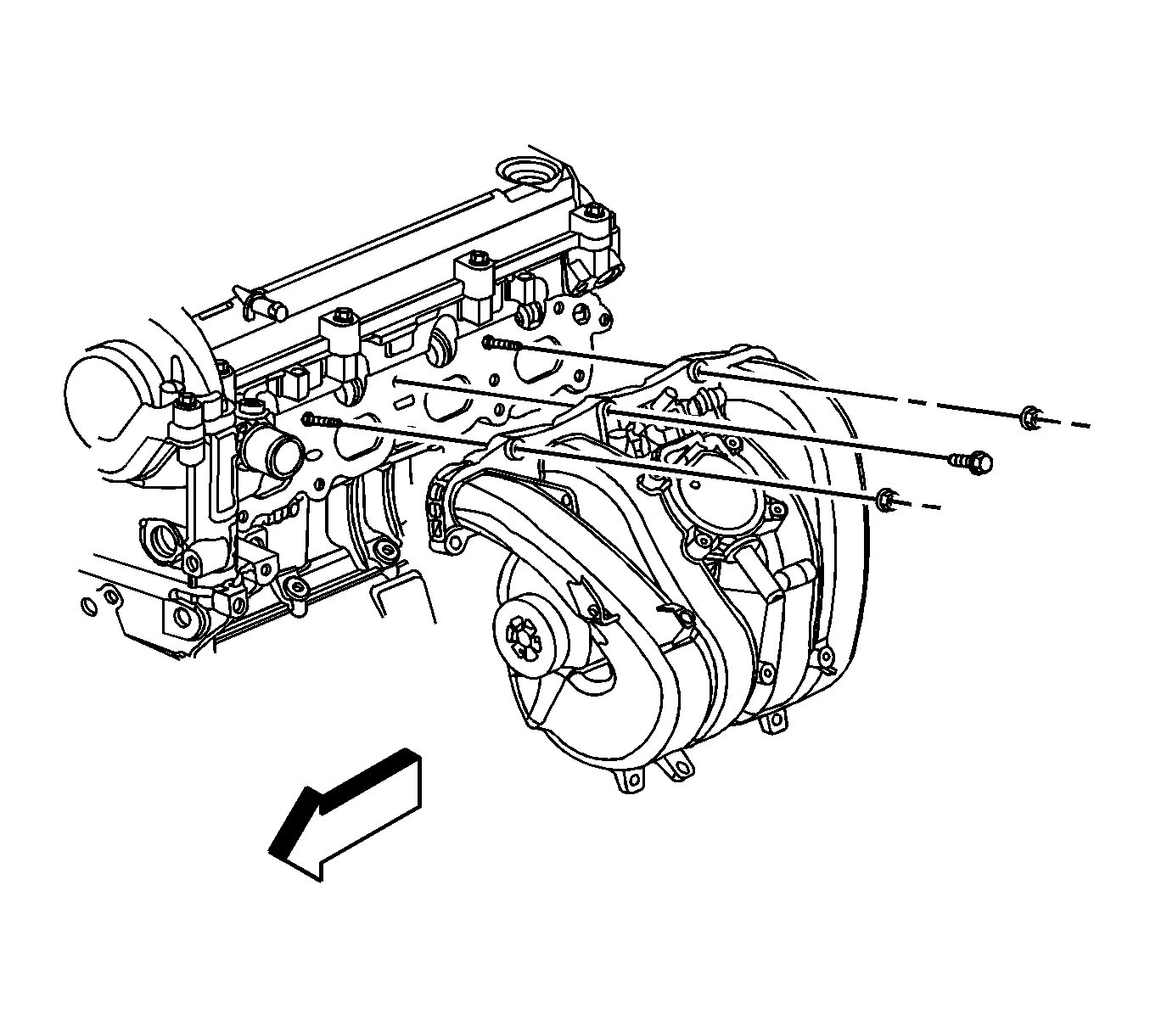
- Remove the intake manifold lower bolts.
- Remove the intake manifold upper bolt and nuts.
- Remove the intake manifold.
- Remove and inspect the intake manifold gasket.
Important: The throttle body seal is reusable, only replace the seal if damaged.
Important: The intake manifold gasket is reusable, only replace the gasket if damage has occurred.
Installation Procedure
- Install a NEW intake manifold gasket if necessary, otherwise install the old gasket.
- Install the intake manifold.
- Install the intake manifold upper bolt and nuts.
- Install the intake manifold lower bolts.
- Position the starter/generator to the bracket.
- Install the starter/generator bolts until snug.
- Tighten the starter generator bolts in the following sequence:
- Install the 3-phase voltage cable bracket to the tie bar.
- Install the 3-phase voltage cable bracket bolt at the tie bar.
- Install the fuel rail. Refer to Fuel Injection Fuel Rail Assembly Replacement .
- Install the oil level indicator tube. Refer to Oil Level Indicator and Tube Replacement .
- Connect the EVAP canister purge tube to the intake manifold and the EVAP solenoid. Refer to Plastic Collar Quick Connect Fitting Service .
- Connect the engine wiring harness electrical connector to the MAP sensor.
- Install a NEW throttle body seal if necessary, otherwise install the old seal.
- Position the throttle body.
- Install the throttle body bolts.
- Install the vacuum brake booster hose (2) to the intake manifold.
- Position the vacuum brake booster hose clamp (1) at the intake manifold.
- Install the engine wiring harness clips (5) to the intake manifold.
- Connect the fuel injector wiring harness electrical connector (7) to the engine wiring harness electrical connector (8).
- Install the fuel injector wiring harness electrical connector retainer (6) to the generator starter.
- Connect the engine wiring harness electrical connector (4) to the generator starter.
- Connect the engine wiring harness electrical connector (2) to the generator starter.
- Connect the engine wiring harness electrical connector (1) to the TAC.
- Install the radiator inlet hose. Refer to Radiator Inlet Hose Replacement .
- Install the air cleaner outlet duct. Refer to Air Cleaner Outlet Duct Replacement .
Notice: Refer to Fastener Notice in the Preface section.
Tighten
Tighten the bolts/nuts to 10 N·m (89 lb in).
| 7.1. | Front |
| 7.2. | Bottom |
Tighten
Tighten the bolts to 58 N·m (43 lb ft).
Tighten
Tighten the bolt to 10 N·m (89 lb in).
Tighten
Tighten the bolts to 10 N·m (89 lb in).
Intake Manifold Replacement LE5
Removal Procedure
- Remove the intake manifold cover. Refer to Intake Manifold Cover Replacement .
- Remove the air cleaner outlet duct. Refer to Air Cleaner Outlet Duct Replacement .
- Disconnect the engine harness electrical connector (1) from the throttle actuator control (TAC).
- Disconnect the engine harness electrical connector (2) from the fuel injector harness.
- Disconnect the engine harness electrical connector from the manifold absolute pressure (MAP) sensor.
- Disconnect the engine harness clips (1 and 3) from the intake manifold.
- Disconnect the engine harness clip (2) from the oil level indicator tube.
- Disconnect the fuel injector electrical connector clip from the intake manifold.
- Reposition the vacuum brake booster hose clamp (1) at the intake manifold.
- Remove the vacuum brake booster hose from the intake manifold.
- Remove the throttle body bolts.
- Remove the throttle body and seal.
- Remove and inspect the throttle body seal.
- Disconnect the evaporative emission (EVAP) canister purge tube from the intake manifold and the EVAP solenoid. Refer to Plastic Collar Quick Connect Fitting Service .
- Remove the oil level indicator tube. Refer to Oil Level Indicator and Tube Replacement .
- Remove the fuel rail. Refer to Fuel Injection Fuel Rail Assembly Replacement .
- Remove the intake manifold lower bolts.
- Remove the intake manifold upper bolt and nuts.
- Remove the intake manifold.
- Remove and inspect the intake manifold gasket.
Important: The throttle body seal is reusable, only replace the seal if damaged.
Important: The intake manifold gasket is reusable, only replace the gasket if damage has occurred.
Installation Procedure
- Install a NEW intake manifold gasket if necessary, otherwise install the old gasket.
- Install the intake manifold.
- Install the intake manifold upper bolt and nuts.
- Install the intake manifold lower bolts.
- Install the fuel rail. Refer to Fuel Injection Fuel Rail Assembly Replacement .
- Install the oil level indicator tube. Refer to Oil Level Indicator and Tube Replacement .
- Connect the EVAP canister purge tube to the intake manifold and the EVAP solenoid. Refer to Plastic Collar Quick Connect Fitting Service .
- Install a NEW throttle body seal if necessary, otherwise install the old seal.
- Position the throttle body.
- Install the throttle body bolts.
- Install the vacuum brake booster hose to the intake manifold.
- Position the vacuum brake booster hose clamp (2) at the intake manifold.
- Connect the engine harness clips (1 and 3) to the intake manifold.
- Connect the engine harness clip (2) to the oil level indicator tube.
- Connect the fuel injector electrical connector clip to the intake manifold.
- Connect the engine harness electrical connector (2) to the fuel injector harness.
- Connect the engine harness electrical connector to the MAP sensor.
- Connect the engine harness electrical connector (1) to the TAC.
- Install the air cleaner outlet duct. Refer to Air Cleaner Outlet Duct Replacement .
- Install the intake manifold cover. Refer to Intake Manifold Cover Replacement .
Notice: Refer to Fastener Notice in the Preface section.
Tighten
Tighten the bolts/nuts to 10 N·m (89 lb in).
Tighten
Tighten the bolts to 10 N·m (89 lb in).
