For 1990-2009 cars only
Removal Procedure
- Perform the High Voltage Disabling procedure. Refer to High Voltage Disabling.
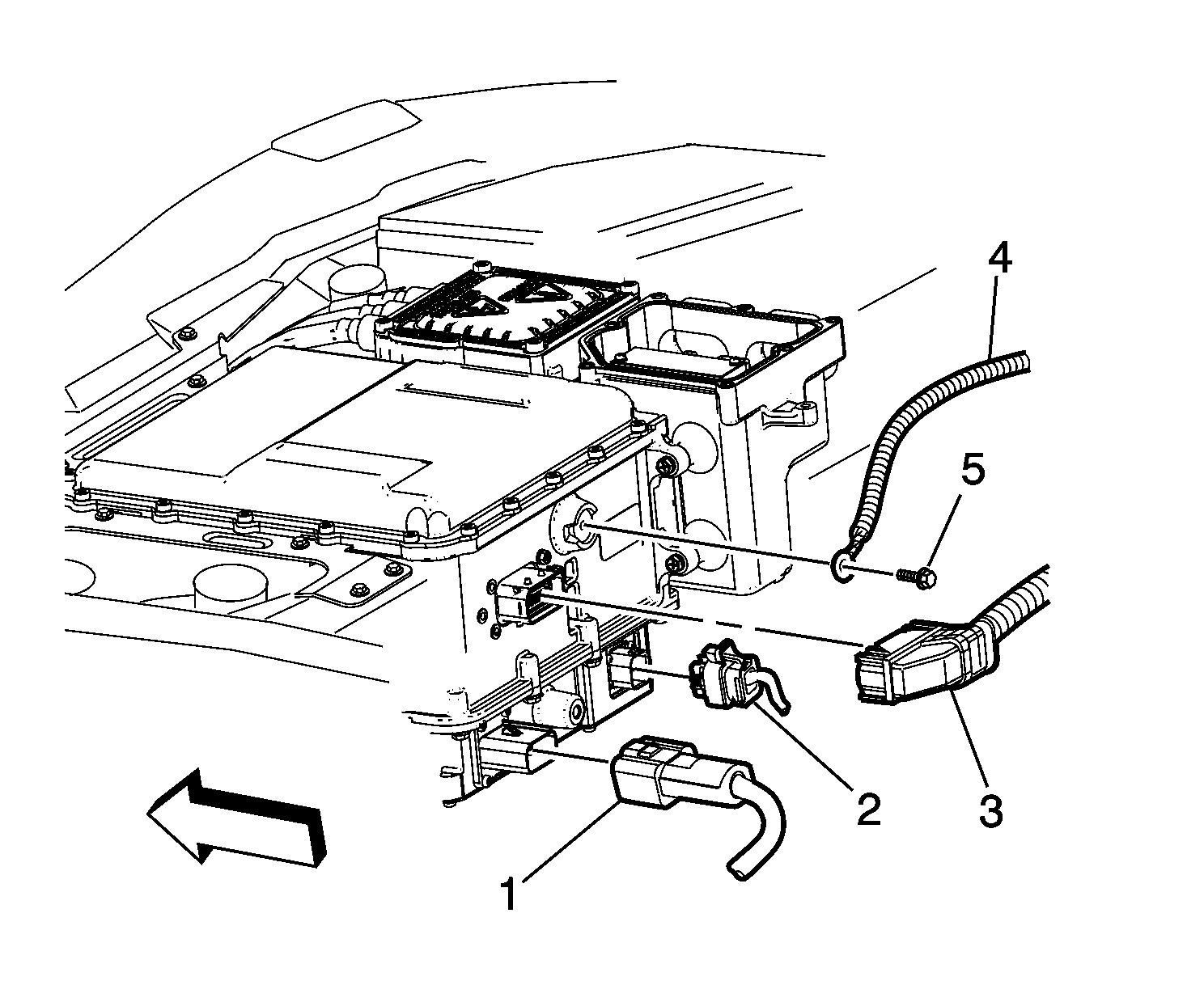
- Disconnect the drive motor generator control module assembly connector (3).
- Remove the drive motor generator position sensor shield circuit fastener (5).
- Remove the shield circuit harness (4).
- Disconnect the accessory DC power control module (APM) assembly connector (2) using the following procedure:
- Disconnect the remaining APM assembly connector (1).
- Drain the power electronics cooling system. Refer to Generator Control Module Cooling System Draining and Filling.
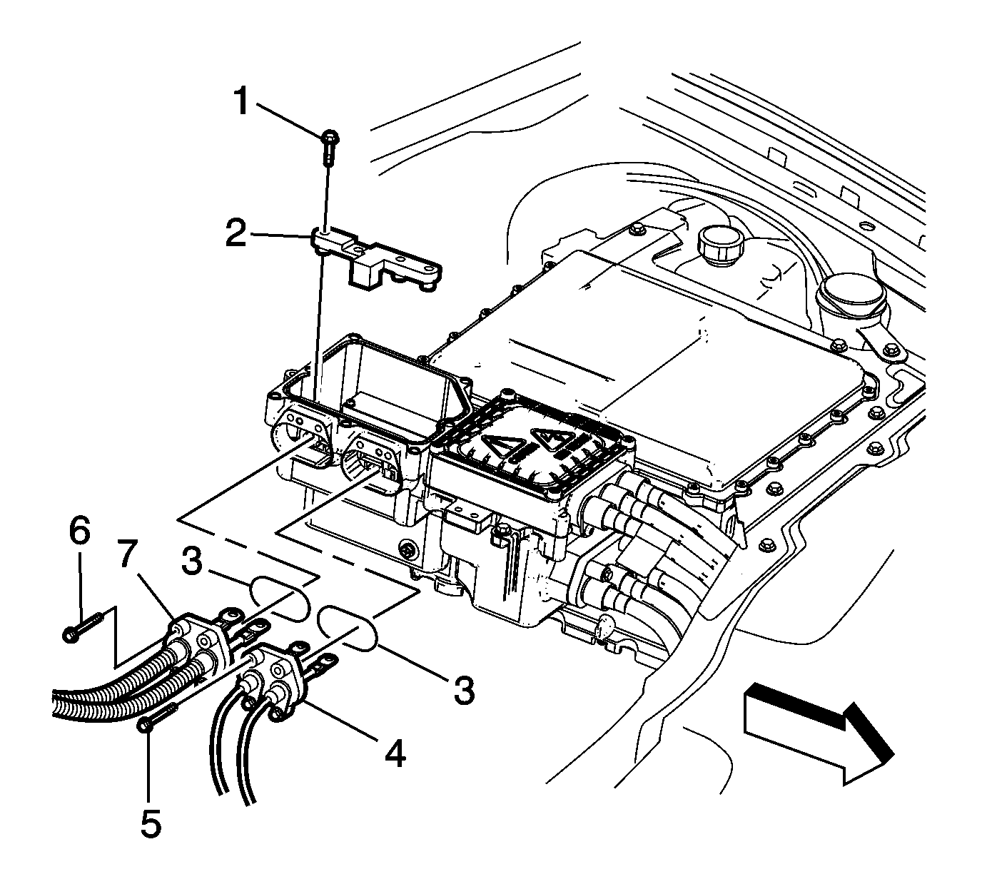
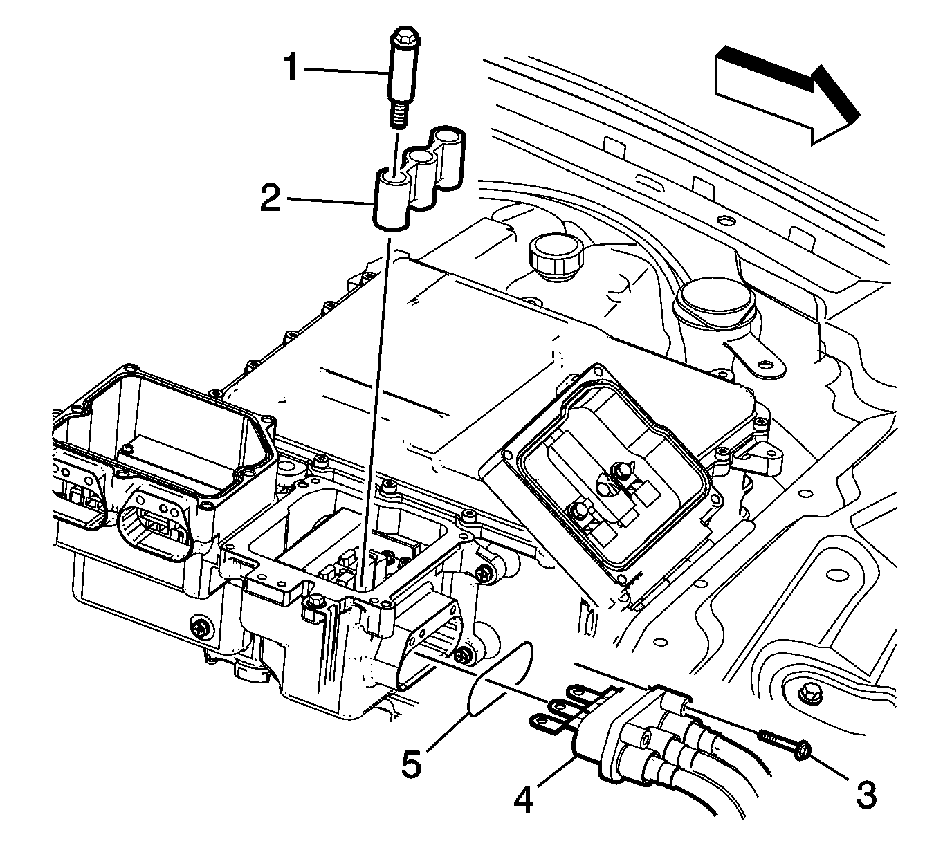
- Remove the HV dc cable terminal fasteners (1).
- Remove the HV dc cable terminal bolt installation guide assembly (2).
- Remove the HV dc electric air conditioning compressor module (ACCM) cable mounting fasteners (5).
- Remove the HV dc electric ACCM cable (4) from the PIM distribution box.
- Remove the HV dc battery cable mounting fasteners (6).
- Remove the HV dc battery cable (7) from the PIM distribution box.
- Inspect and retain the seals (3).
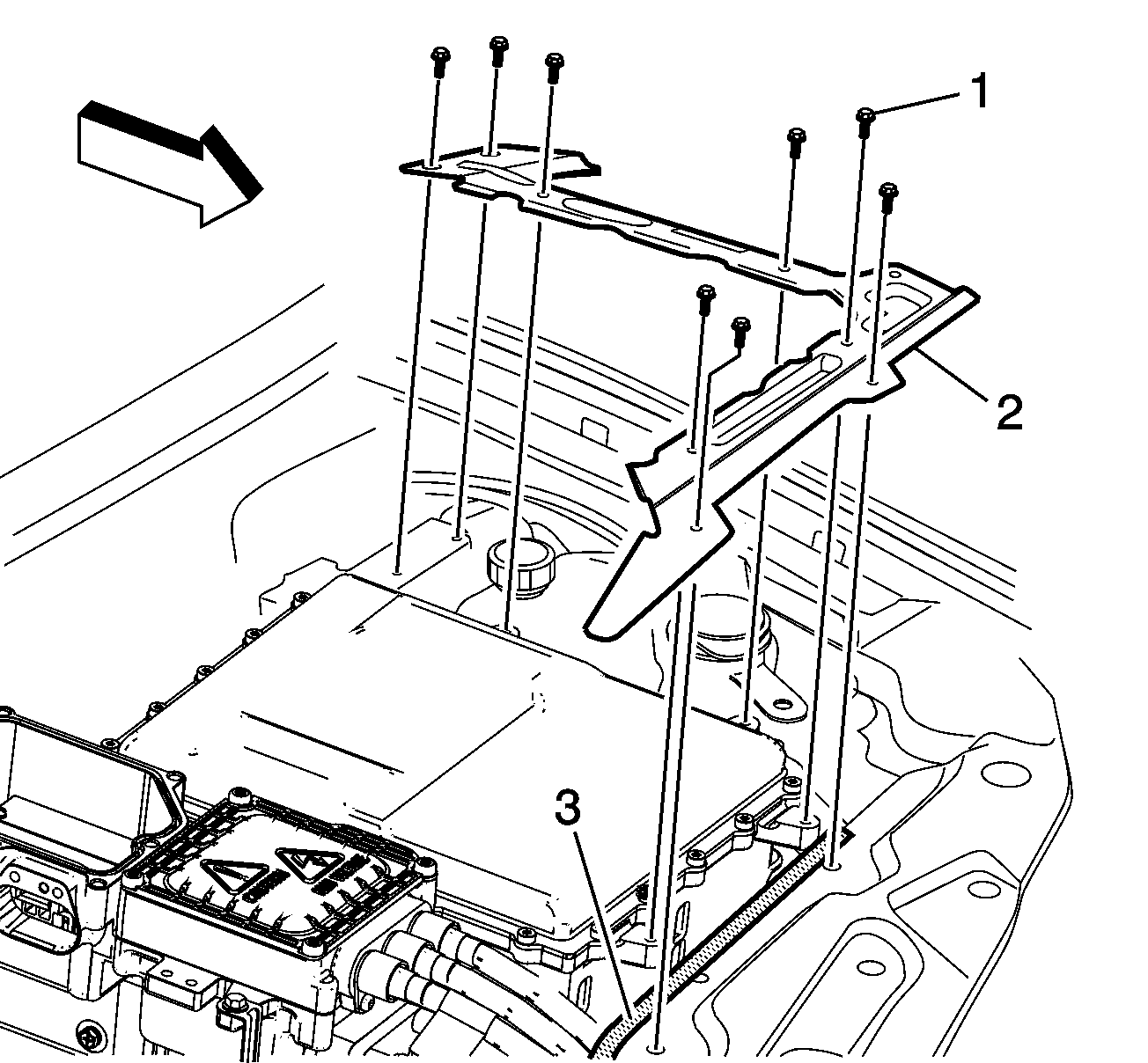
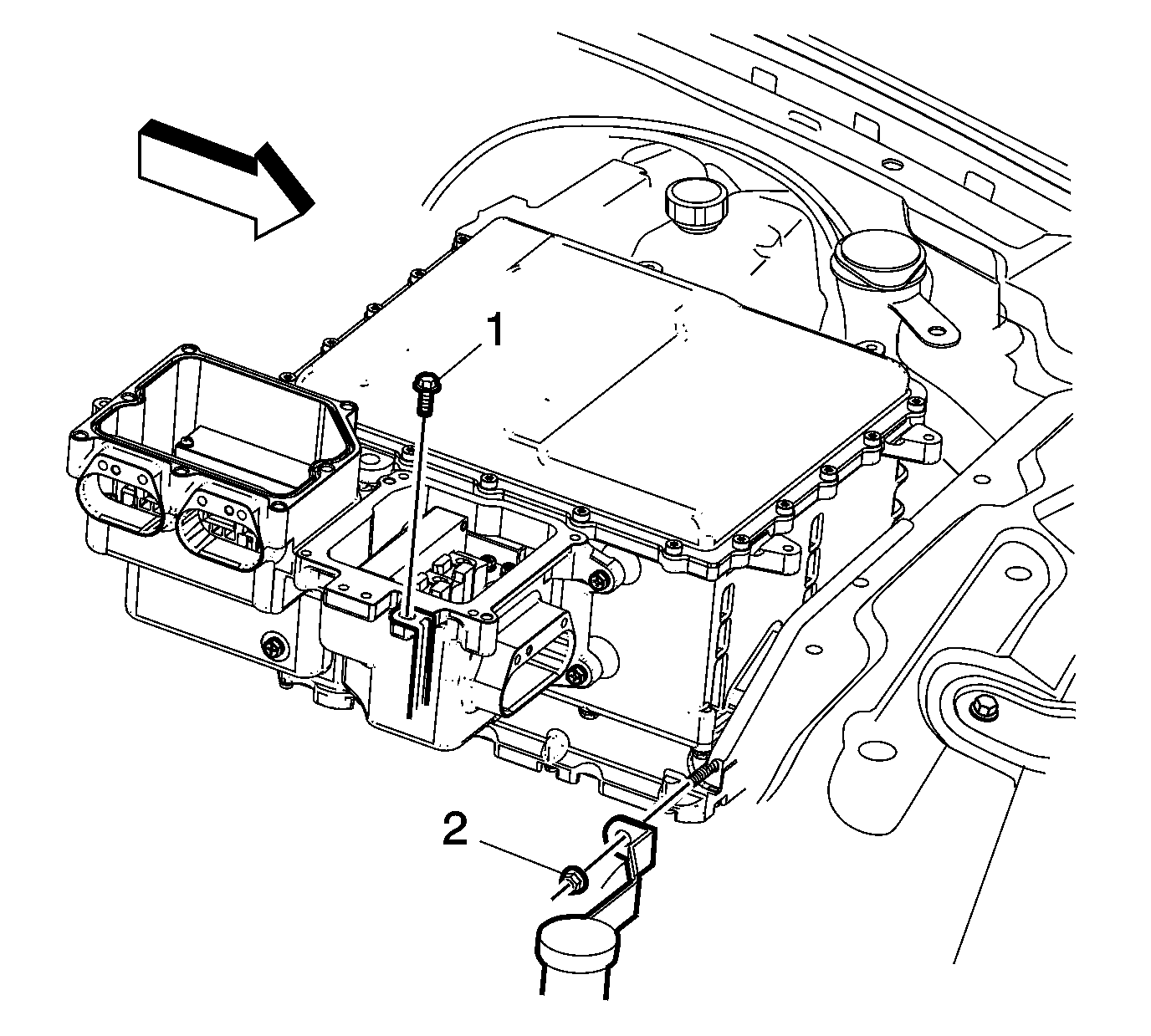
- Remove the drive motor generator control module brace bolts (1) and brace (2).
- Place a protective guard (3) such as wiring conduit along the sharp edge of the front crossmember to protect the high voltage cables.
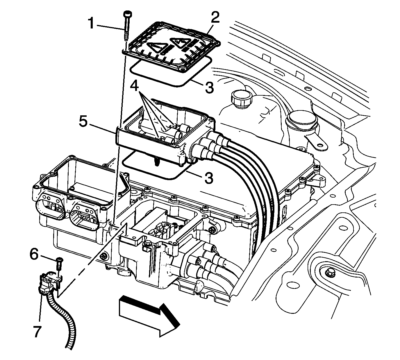
- Remove the drive motor generator power inverter control module (PIM) 3 phase cable terminal cover fasteners (1).
- Remove the PIM 3 phase cable terminal cover (2).
- Remove the PIM 3 phase cable terminal fastener (4).
- Remove the PIM 3 phase cable terminal seals (3) and discard.
- Remove the sight shield circuit breaker fasteners (6).
- Remove the sight shield circuit breaker (7).
- Remove the PIM 3 phase cable terminal fasteners (1) and installation guide assembly (2).
- Remove the PIM 3 phase cable mounting fasteners (3) and terminal (4).
- Remove the PIM 3 phase cable terminal seal (3) and discard.
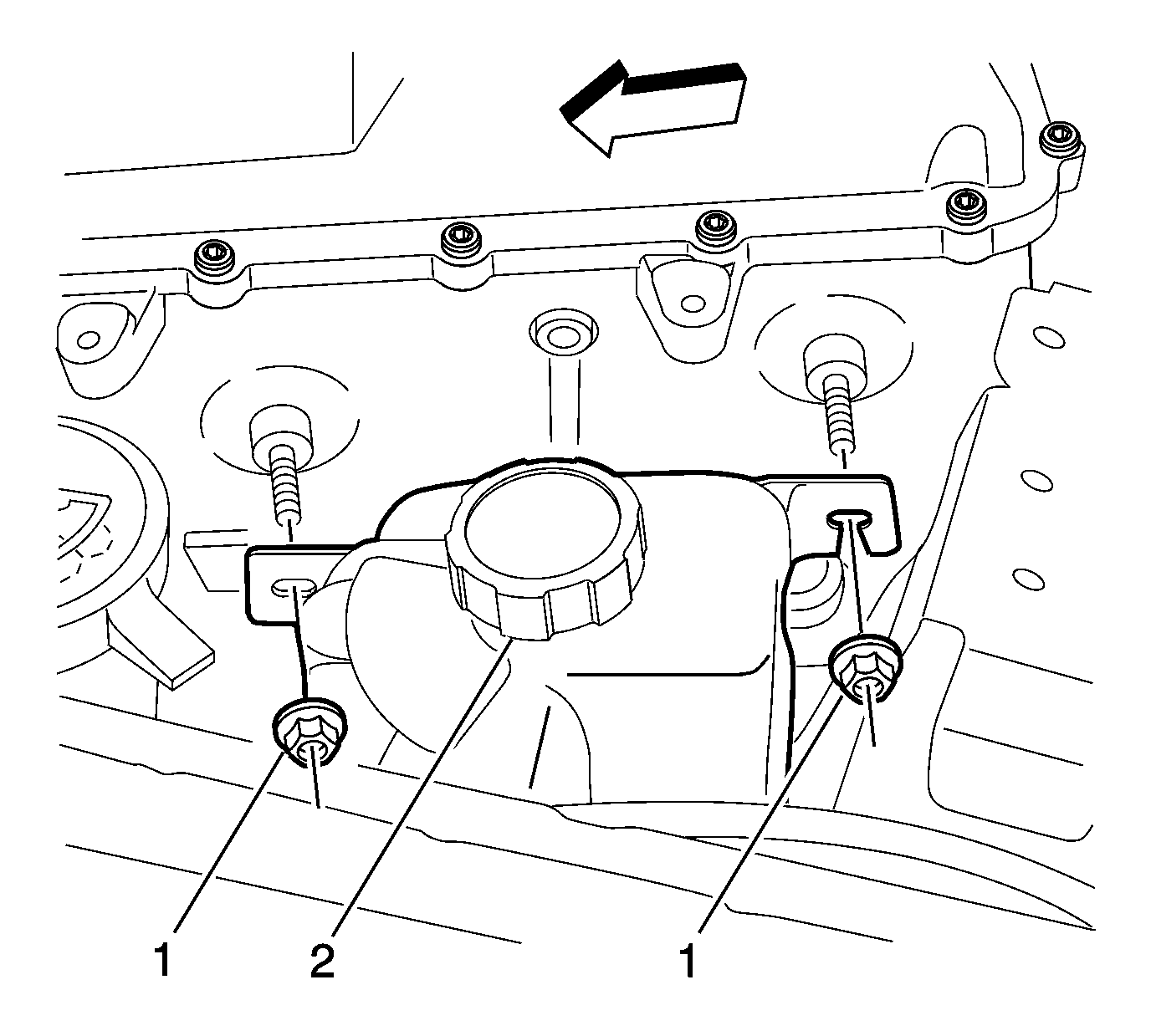
- Remove the hybrid cooling reservoir fasteners (1) and pull the reservoir (2) off of the control module studs.
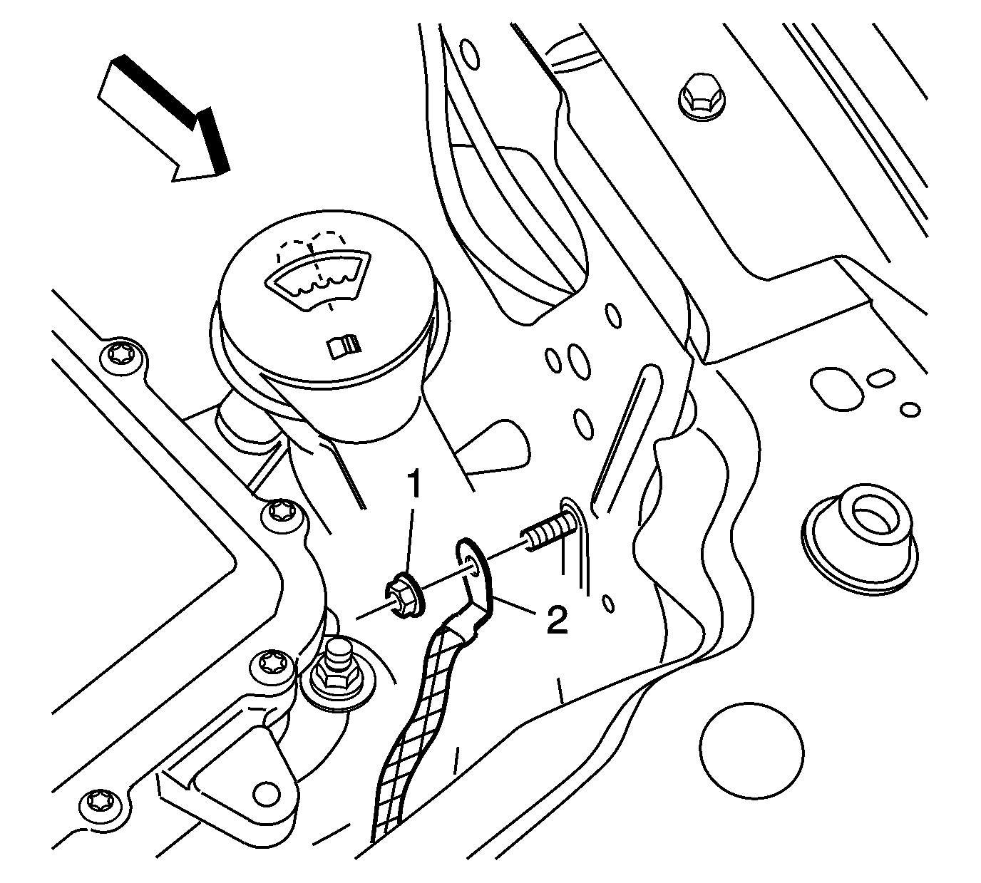
- Remove the ground strap fastener (1) and strap (2) from the left front inner fender.
- Remove the underhood fuse block support fastener (1) and pull the support away from the control module.
- Remove the engine coolant surge tank support fastener (2) and pull the support from the control module stud.
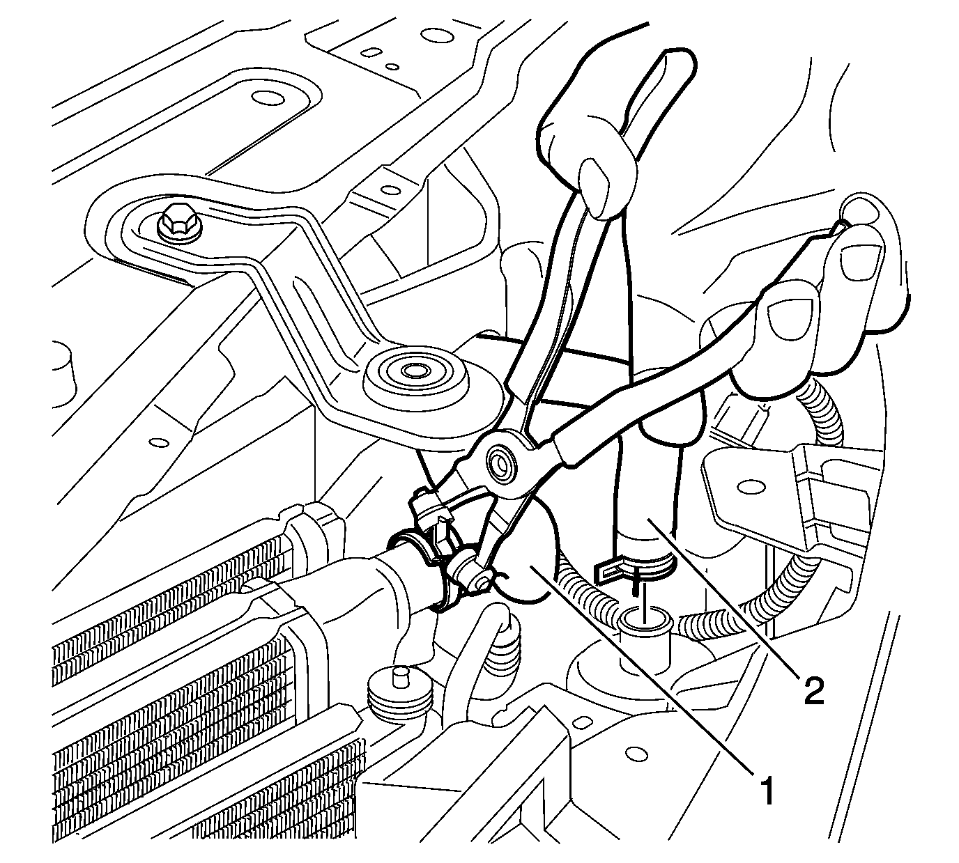
- Remove the coolant hoses (1-2) from the cooler and the air separator.
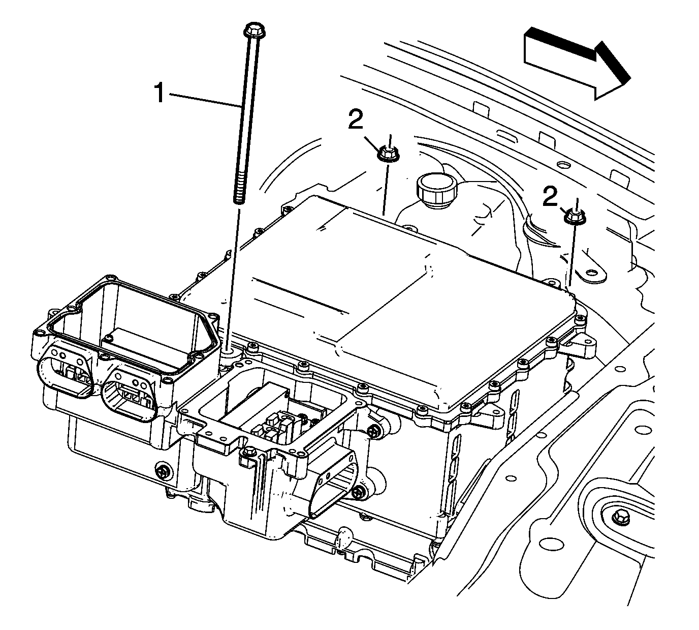
- Remove the control module retainer bolt (1) and nuts (2).
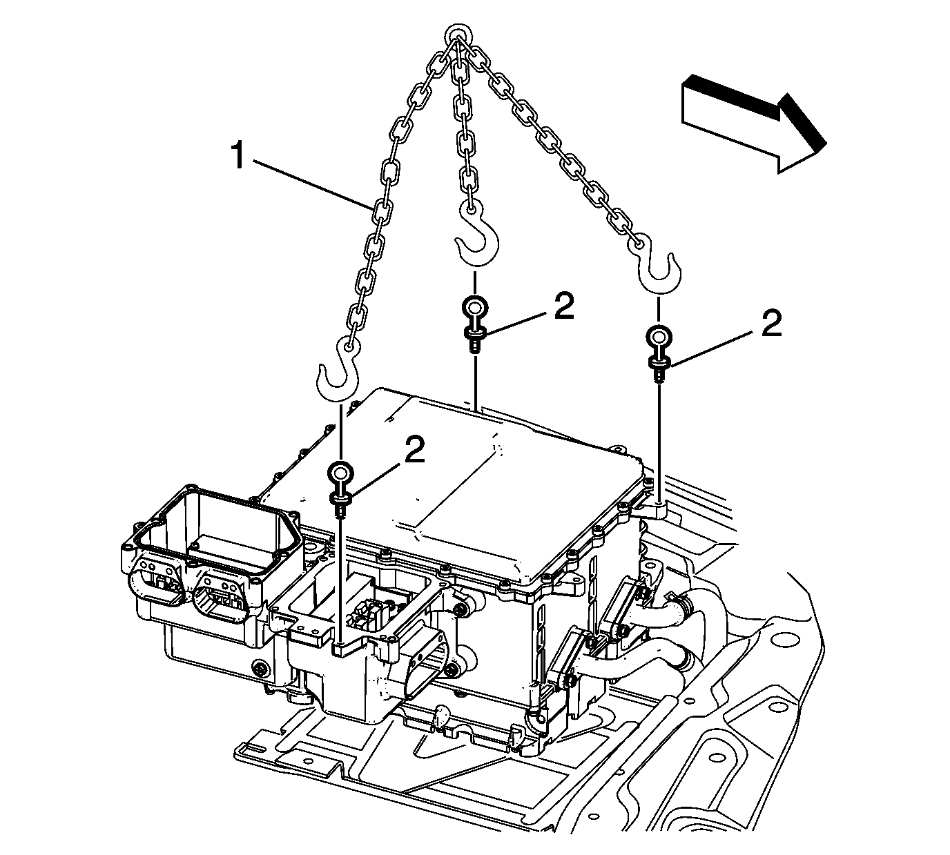
- Attach a lifting device (1 and 2) to the drive motor generator control module assembly at the 3 identified locations.
- Lift the drive motor generator control module assembly from the vehicle while feeding the coolant hoses through the support opening.
- To replace the drive motor generator power inverter module (PIM) assembly, refer to Drive Motor Generator Power Inverter Module Removal and Installation. To replace the accessory DC power control module (APM), refer to Accessory DC Power Control Module Removal and Installation.
Danger: Always perform the High Voltage Disabling procedure prior to servicing any High Voltage component or connection. Personal Protection Equipment (PPE) and proper procedures must be followed.
The High Voltage Disabling procedure will perform the following tasks:| • | Identify how to disable high voltage. |
| • | Identify how to test for the presence of high voltage. |
| • | Identify condition under which high voltage is always present and personal protection equipment (PPE) and proper procedures must be followed. |
| 5.1. | Remove the locking tab. |
| 5.2. | Insert a small flat blade screwdriver into the locking tab area and raise the tab while pulling on the connector. |
Caution: High Voltage (HV) cables should never be removed from the mounting block. Removal of the individual HV cable from the mounting block may result in HV cable and/or component damage from improper:
• Cable sealing • Electrical shielding • Terminal position assurance
Installation Procedure
- Attach a lifting device (1-2) to the drive motor generator control module assembly at the three identified locations.
- Lower the drive motor generator control module assembly into the vehicle while feeding the coolant hoses through the support opening.
- Install the coolant hoses (1-2) onto the cooler and the air separator.
- Install the control module retaining bolt (1), mounting nuts (2), and tighten the mounting bolt and nuts to 9 N·m (80 lb in).
- Install the underhood fuse block support and fastener (1) onto the control module. Tighten the bolt to 5 N·m (44 lb in).
- Install the engine coolant surge tank support and nut (2) onto the control module stud. Tighten the nut to 5 N·m (44 lb in).
- Install the ground strap (2) and fastener (1) onto the left front inner fender stud and tighten to 9 N·m (80 lb in).
- Install the hybrid cooling reservoir (2) and fasteners (1) onto the control module studs and tighten to 9 N·m (80 lb in).
- Install a new seal (5) and the PIM 3 phase cable terminal (4).
- Install the PIM 3 phase cable terminal mounting fasteners (3) and tighten to 9 N·m (80 lb in).
- Install the PIM 3 phase cable terminal installation guide assembly (2) and fasteners (1). Tighten to 9 N·m (80 lb in).
- Install NEW PIM 3 phase cable terminal seals (3).
- Install the PIM 3 phase cable terminal (5).
- Install the PIM 3 phase cable terminal fasteners (4) and tighten to 9 N·m (80 lb in).
- Install the PIM 3 phase cable terminal cover (2).
- Install the PIM 3 phase cable terminal cover fasteners (1) and tighten to 9 N·m (80 lb in).
- Install the sight shield circuit breaker (7).
- Install the sight shield circuit breaker fasteners (6) and tighten to 9 N·m (80 lb in).
- Remove the protective guard (3) from the front crossmember.
- Install the drive motor generator control module brace (2) and bolts (1). Tighten the bolts to 9 N·m (80 lb in).
- Inspect and install the seals (3).
- Install the HV dc battery cable (7) onto the PIM distribution box.
- Install the HV dc battery cable mounting fasteners (6) and tighten to 9 N·m (80 lb in).
- Install the HV dc electric ACCM cable (4) onto the PIM distribution box.
- Install the HV dc electric ACCM cable mounting fasteners (5) and tighten to 9 N·m (80 lb in).
- Install the HV dc cable terminal bolt installation guide assembly (2).
- Install the HV dc cable terminal fasteners (1) and tighten to 9 N·m (80 lb in).
- Connect the APM assembly connectors (1-2) and install any removed locking tabs.
- Connect the drive motor generator control module assembly connector (3) using the following procedure:
- Install the shield circuit harness (4) and retainer (5). Tighten to 9 N·m (80 lb in).
- Fill the power electronics cooling system and test for leaks at all serviced connections. Refer to Generator Control Module Cooling System Draining and Filling.
- Install the sight shield. Refer to Drive Motor Generator Control Module Sight Shield Replacement.
- Perform the High Voltage Enabling procedure. Refer to High Voltage Enabling
- For control module programming and setup procedures, refer to Control Module References.


Caution: Refer to Fastener Caution in the Preface section.


| 29.1. | Push the lever up. |
| Note: Install the connector (3) without disturbing the position of the lever. DO NOT use the lever to install the connector in place. |
| 29.2. | Install the connector (3) onto the terminals by pushing on the connector only. |
| 29.3. | Rotate the lever after the terminals are engaged. |
| 29.4. | Push the green tab to lock the lever. |
