Removal Procedure
- Loosen the clamp at the air cleaner assembly and throttle body assembly.
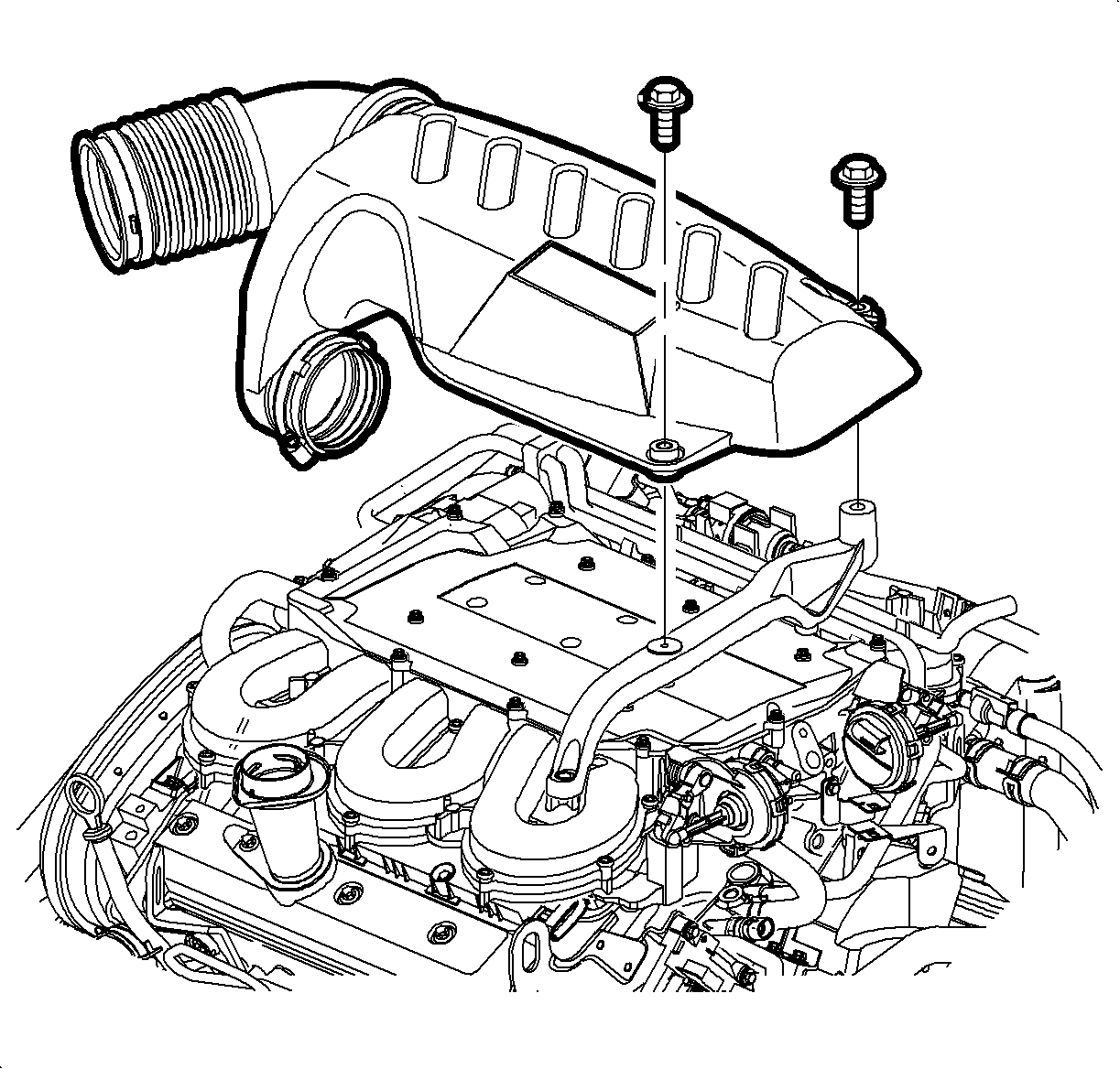
- Remove the attachment bolts from the outlet resonator/duct assembly to support bracket.
- Remove the outlet resonator/duct assembly.
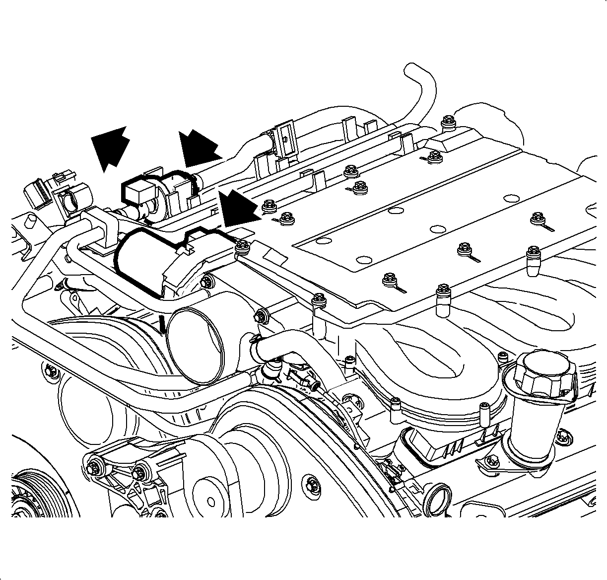
- Disconnect the purge solenoid from the manifold to allow sufficient clearance when removing the upper exhaust manifold nut.
- Remove the middle exhaust manifold nut using a boxed end wrench.
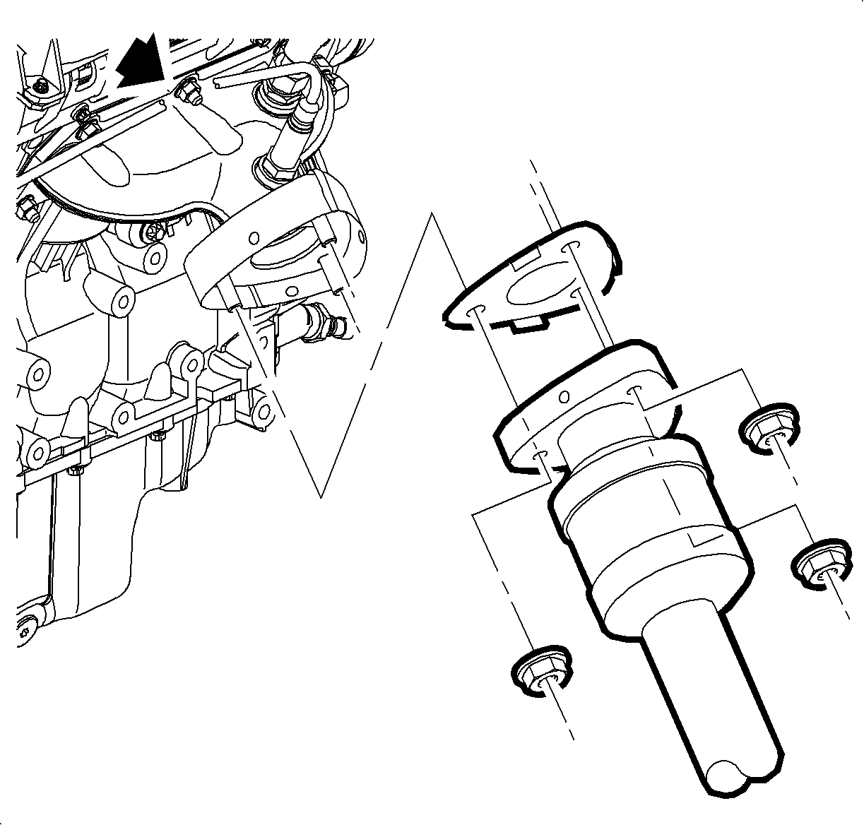
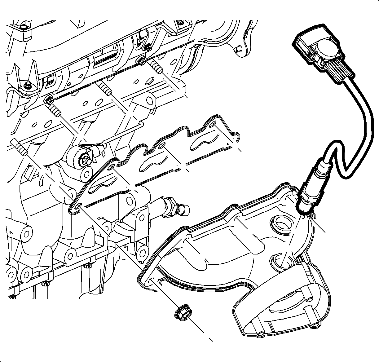
- Disconnect the bank #1 02 sensor #1 connector at the rear of the engine.
- Raise the vehicle.
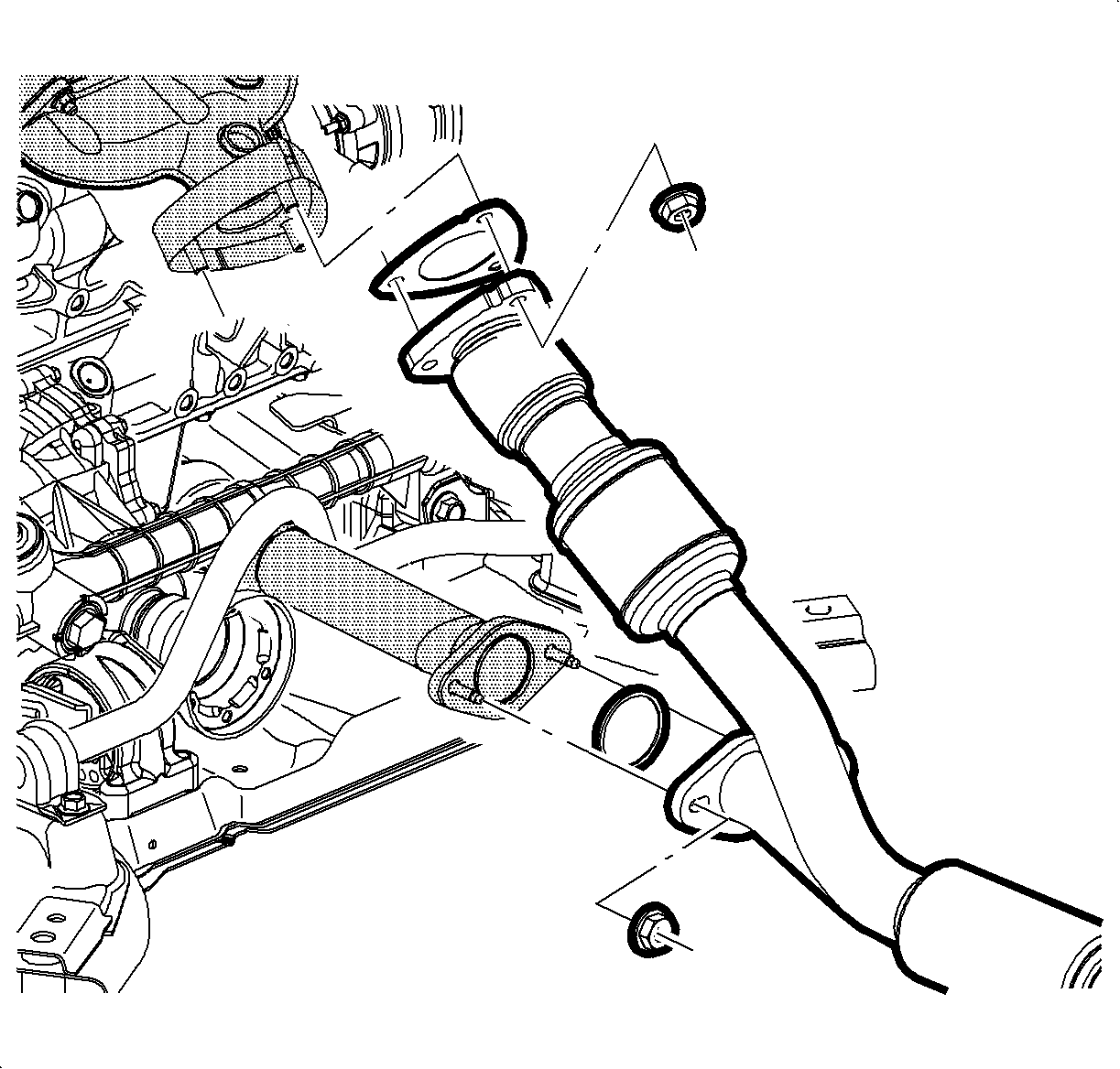
- Remove the rear exhaust down pipe assembly. Refer to Exhaust Manifold Pipe Replacement
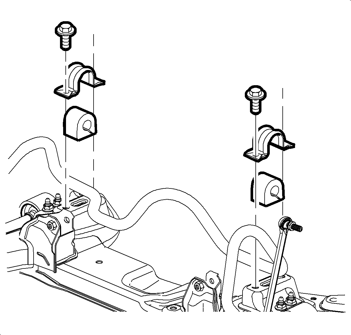
- Remove the right hand stabilizer bar to frame mounting bolts.
- Remove the left and right hand stabilizer bar to lower link nut and discard the nut.
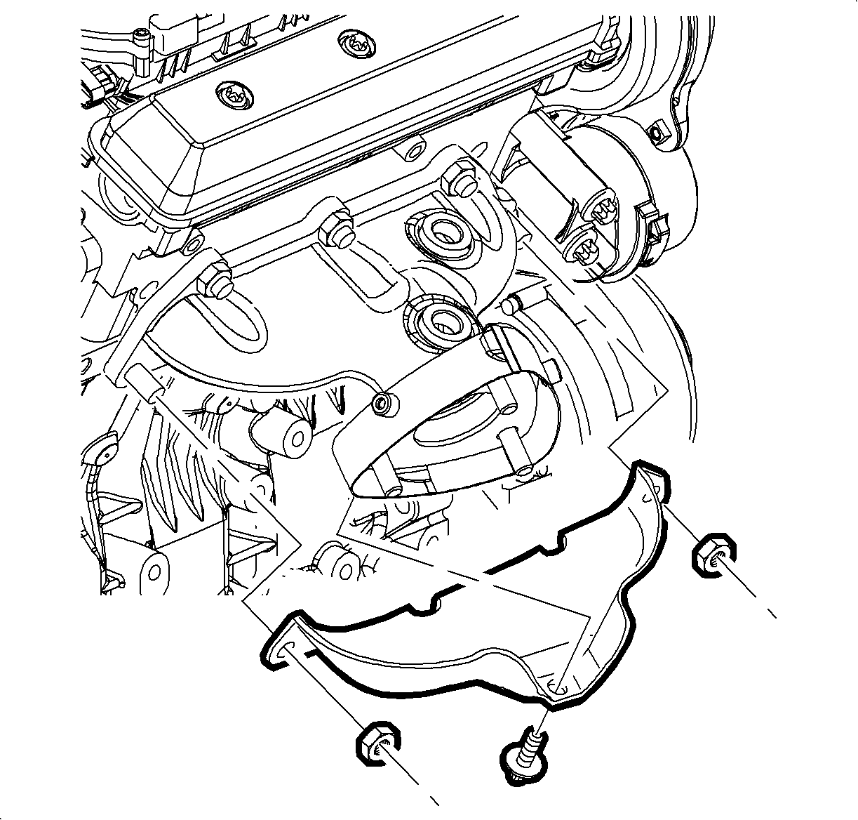
- Remove the exhaust heat shield bolts.
- Remove the exhaust heat shield.
- Remove the exhaust manifold nuts to the cylinder head.
- Remove the rear exhaust manifold and gasket.
Important: Access to the middle exhaust manifold nut to limited from under vehicle.
Important: Due to a clearance issue, when removing rear exhaust manifold (with 02 sensor), the right hand side of stabilizer bar must be rotated and positioned away from exhaust manifold.
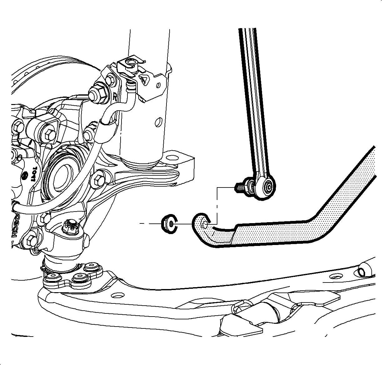
Notice: Do not allow the stud to rotate when removing or installing the right hand stabilizer nut. Secure the stud with a wrench while removing or installing the nut to prevent damage to the link.
Installation Procedure
- Transfer the 02 sensor to the manifold if the manifold is being replaced.
- Install the new manifold gasket on the cylinder head.
- Install the exhaust manifold.
- Install the exhaust manifold nuts except for the outer nuts that will hold the heat shield to the manifold.
- Install the exhaust heat shield.
- Install the exhaust manifold heat shield nuts and bolt.
- Connect the 02 sensor connector near the rear of the engine.
- Install the right hand stabilizer bar to frame bolts.
- Install the new nuts, left and right hand stabilizer bar to stabilizer link and tighten.
- Install the rear exhaust manifold down pipe assembly. Exhaust Manifold Pipe Replacement .
- Lower the vehicle.
- Attach the 02 electrical connector to bracket.
- Install the middle exhaust manifold nut.
- Re-position the purge valve to the intake manifold.
- Install the outlet resonator/duct assembly into position.
- Tighten the clamp at the throttle body assembly into position.
- Position the outlet resonator/duct assembly to support bracket and install the bolts.
- Tighten the clamp at the air cleaner assembly.
Important: Whenever the oxygen sensor is removed, coat the threads with nickel-based anti-seize compound such as SA P/N 21485279 (or equivalent). Never use silicon products, silicon products will cause damage to oxygen sensor.
Tighten
Tighten the oxygen sensor-to-exhaust manifold pipe - L81 to 45 N·m
(33 lb ft).
Tighten
Tighten the exhaust manifold nuts - L81 to 20 N·m (15 lb ft).
Tighten
Tighten the exhaust manifold nuts - L81 to 20 N·m (15 lb ft).
Tighten
Tighten the exhaust manifold heat shield bolt - L81 to 25 N·m
(15 lb ft)
Tighten
Tighten the stabilizer bar-to-frame bolts -- L81 to 50 N·m
(37 lb ft).
Notice: Do not allow the stud to rotate when removing or installing the right hand stabilizer nut. Secure the stud with a wrench while removing or installing the nut to prevent damage to the link.
Tighten
Tighten the stabilizer link nuts - L81 to 65 N·m (48 lb ft).
Tighten
Tighten the exhaust manifold nuts - L81 to 20 N·m(15 lb ft).
Tighten
Tighten outlet resonator/duct assembly-to-support bracket bolts -
L81 10 N·m (89 lb in).
