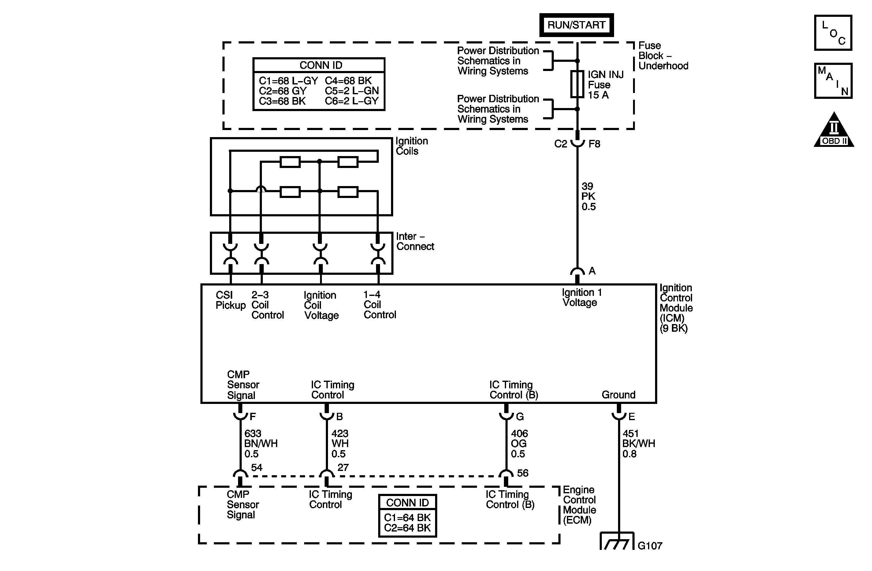
System Description
The powertrain control module (PCM) uses information from the crankshaft position (CKP) sensor and the ignition control module (ICM) in order to determine when an engine misfire is occurring. By monitoring variations in the crankshaft rotation speed for each cylinder, the PCM is able to detect individual misfire events. A misfire rate that is high enough can cause the 3-way catalytic converter (TWC) to overheat under certain driving conditions. The malfunction indicator lamp (MIL) will flash ON and OFF when the conditions for TWC overheating are present. If the PCM detects a misfire rate for a specific cylinder sufficient to cause emission levels to exceed mandated standards, DTC P0301, P0302, P0303, or P0304 will set.
Conditions for Running the DTC
| • | DTC P0105, P0107, P0108, P0112, P0113, P0116, P0117, P0118, P0122, P0123, P0125, P0128, P0130, P0131, P0132, P0133, P0134, P0171, P0172, P0335, P0341, P0502, P0503, P0506, P0507, P0601, P0742, P1133, P1336, P1621 are not set. |
| • | The engine speed is between 469-6,400 RPM. |
| • | The ignition voltage is between 9-17 volts. |
| • | The engine coolant temperature (ECT) is between -7 and +130°C (20-254°F). |
| • | The engine has been running more than 5 seconds. |
| • | The fuel level is more than 10 percent. |
Conditions for Setting the DTC
The PCM is detecting a crankshaft rotation speed variation indicating a misfire sufficient to cause emission levels to exceed mandated standards.
Action Taken When the DTC Sets
| • | The control module illuminates the malfunction indicator lamp (MIL) on the second consecutive ignition cycle that the diagnostic runs and fails. |
| • | The control module records the operating conditions at the time the diagnostic fails. The first time the diagnostic fails, the control module stores this information in the Failure Records. If the diagnostic reports a failure on the second consecutive ignition cycle, the control module records the operating conditions at the time of the failure. The control module writes the operating conditions to the Freeze Frame and updates the Failure Records. |
Conditions for Clearing the MIL/DTC
| • | The control module turns OFF the malfunction indicator lamp (MIL) after 3 consecutive ignition cycles that the diagnostic runs and does not fail. |
| • | A current DTC, Last Test Failed, clears when the diagnostic runs and passes. |
| • | A history DTC clears after 40 consecutive warm-up cycles, if no failures are reported by this or any other emission related diagnostic. |
| • | Clear the MIL and the DTC with a scan tool. |
Step | Action | Values | Yes | No |
|---|---|---|---|---|
1 | Did you perform the Diagnostic System Check-Engine Controls? | -- | Go to Step 2 | |
2 |
Are any of the misfire current counters incrementing? | -- | Go to Step 3 | Go to Intermittent Conditions |
3 | Are any DTCs other than DTC P0300 set? | -- | Go to Step 4 | |
4 | Can any abnormal engine noise be heard? | -- | Go to Symptoms - Engine Mechanical in Engine Mechanical | Go to Step 5 |
5 |
Important: DO NOT remove the ignition control (IC) module and connector from the ignition coil housing. Important: Not grounding the ignition coil housing may cause erratic spark. Does the spark tester spark? | -- | Go to Step 7 | Go to Step 6 |
6 | Inspect the affected cylinder spark plug boot for a missing or damaged ignition coil spring. Did you find and correct the condition? | -- | Go to Step 16 | Go to Step 15 |
7 |
Does the spark plug appear to be OK? | -- | Go to Step 8 | Go to Step 9 |
8 |
Did the misfire move with the spark plug? | -- | Go to Step 14 | Go to Step 12 |
9 | Is the spark plug oil or coolant fouled? | -- | Go to Symptoms - Engine Mechanical in Engine Mechanical | Go to Step 10 |
10 | Is the spark plug gas fouled? | -- | Go to Step 12 | Go to Step 11 |
11 | Does the spark plug show any signs of being cracked, worn, or improperly gapped? | -- | Go to Step 13 | Go to Step 12 |
12 | Perform the fuel injector coil test. Refer to Fuel Injector Solenoid Coil Test . Did you find and correct the condition? | -- | Go to Step 16 | Go to Symptoms - Engine Mechanical in Engine Mechanical |
13 | Replace or gap the spark plug. Refer to Spark Plug Replacement . If an improper gap is found, be sure to gap the spark plugs using a wire type gage. Did you complete the action? | -- | Go to Step 16 | -- |
14 | Replace the faulty spark plug. Refer to Spark Plug Replacement . Did you complete the replacement? | -- | Go to Step 16 | -- |
15 | Replace the ignition coil housing. Refer to Ignition Coil Housing Replacement . Did you complete the replacement? | -- | Go to Step 16 | -- |
16 | Was the customer concern the MIL flashing? | -- | Go to Step 17 | Go to Step 18 |
17 |
Does the DTC run and pass? | 2,500 RPM | Go to Step 18 | Go to DTC P0420 |
18 |
Did the DTC fail this ignition? | -- | Go to Step 2 | Go to Step 19 |
19 | Observe the Capture Info with a scan tool. Are there any DTCs that have not been diagnosed? | -- | System OK |
