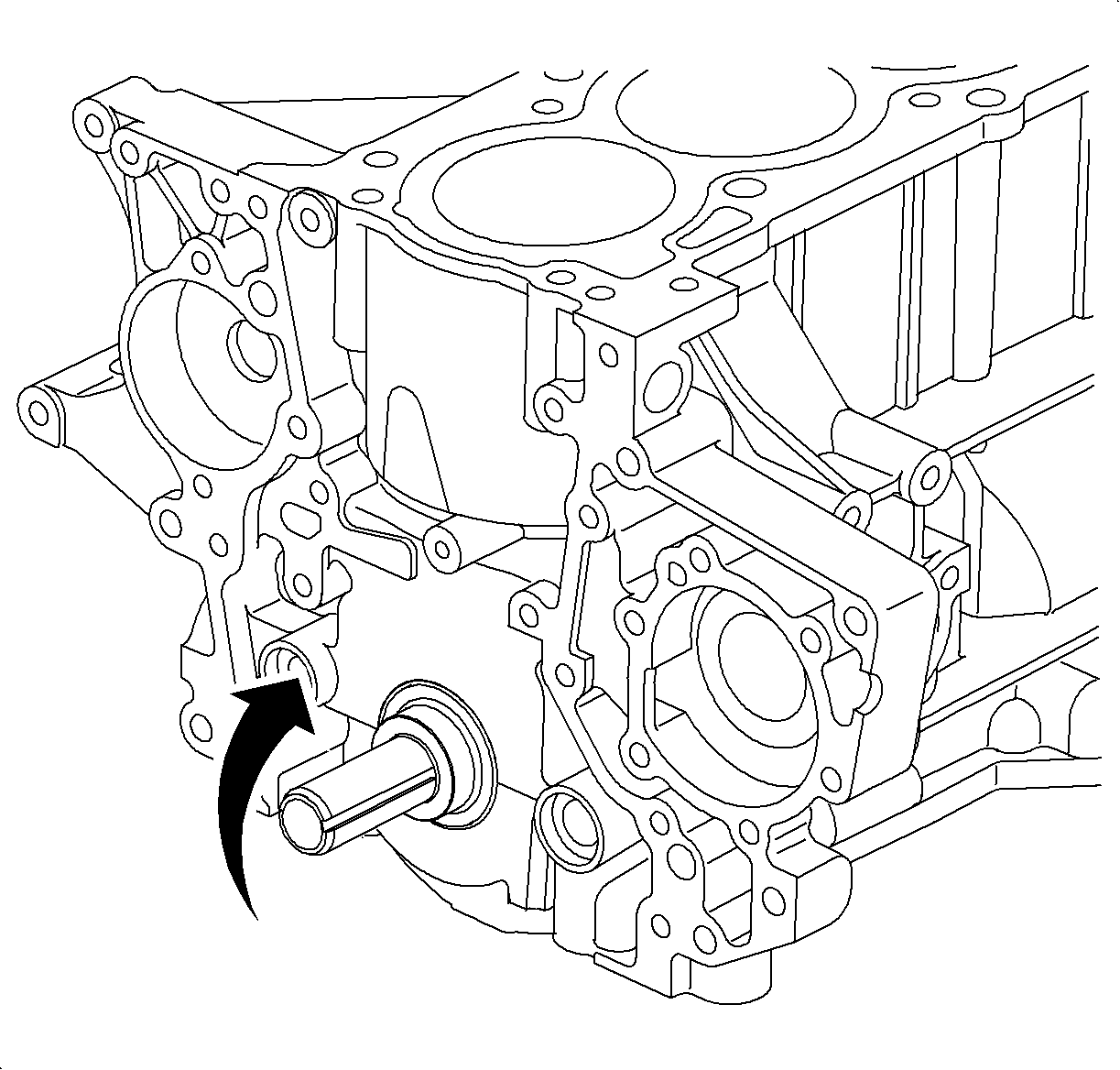
- Clean the top of the pistons
and the top of the block:
| 1.1. | Turn the crankshaft and bring each piston to top dead center (TDC).
Using a gasket scraper, remove all of the carbon from the piston top. |
| | Important: Cover the front of the engine with a shop towel to prevent debris from
entering the engine.
|
| 1.2. | Remove all gasket material from the top of the block using a plastic
or wood scraper. |
| | Caution: Wear safety glasses when using compressed air in order to prevent eye injury.
|
| 1.3. | Blow carbon and oil from the bolt holes. |
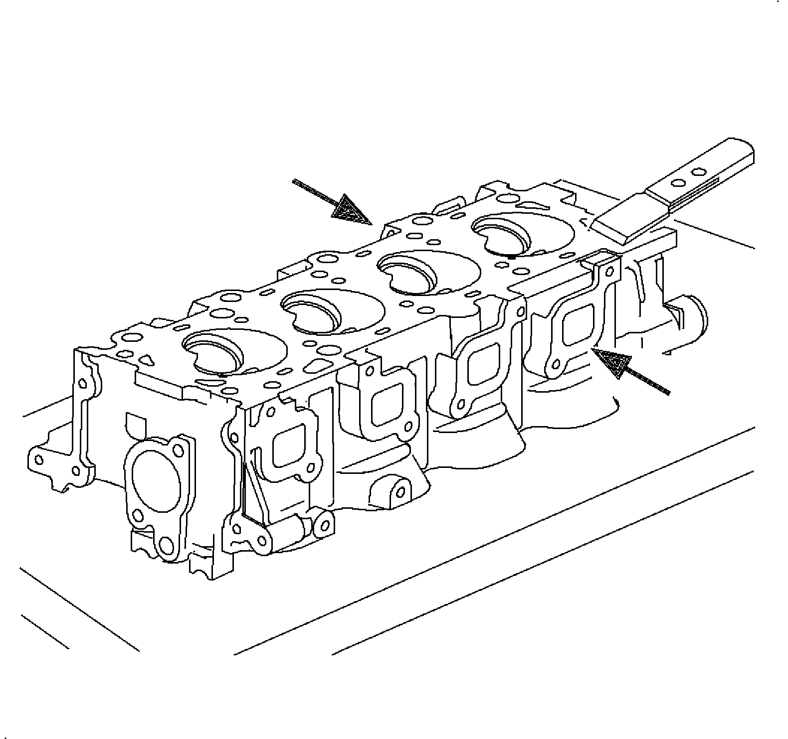
Notice: Intake and exhaust manifold stud threads can be damaged during removal and must
be replaced when a new machined cylinder head casting is installed.
Notice: Be careful not to damage the aluminum the aluminum cylinder head and block gasket
sealing surfaces when removing the cylinder head or during cleaning.
- To remove gasket material, use a plastic or wood gasket
scraper. Remove all gasket material from the manifold and head surfaces.
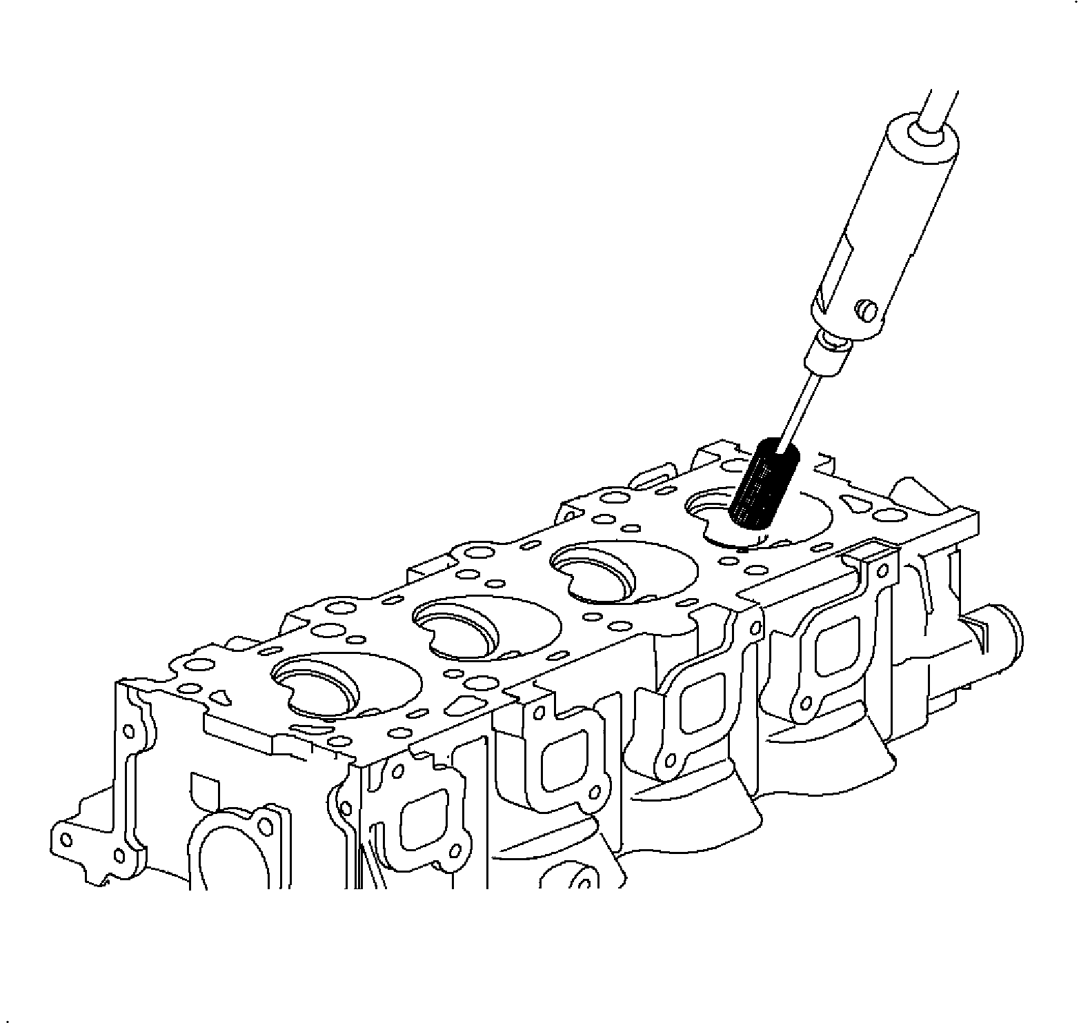
- Using a wire brush, remove
all carbon from the combustion chambers.
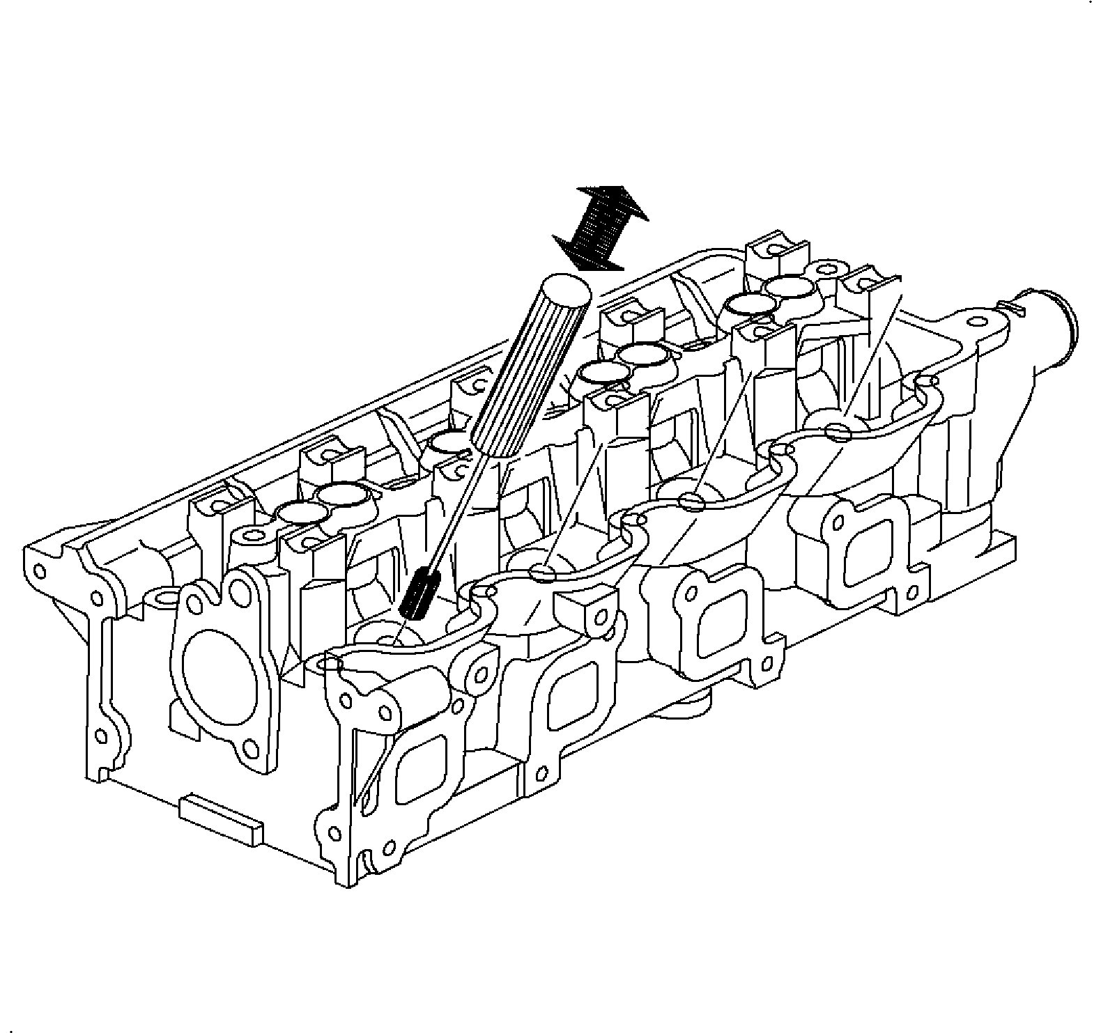
- Using a valve guide brush
and solvent, clean all of the valve guide bushings.
- Using a soft brush and solvent, thoroughly clean the cylinder
head:
| • | Intake and exhaust parts |
| • | Intake and exhaust valve seats |
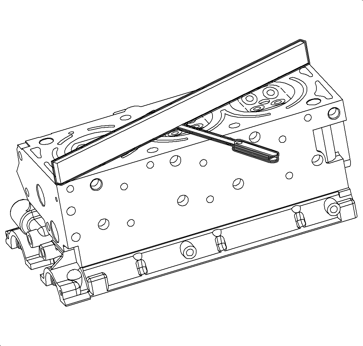
- Inspect the cylinder head
for flatness. Using a precision SA9177NE
and SA91101NE
, measure the surfaces contacting the cylinder block and manifolds
for warpage. If warpage is greater than the maximum, replace the cylinder
head.
Specifications
The maximum warpage cylinder block side is 0.025 mm/100 mm
(0.0010 in/3.917 in).
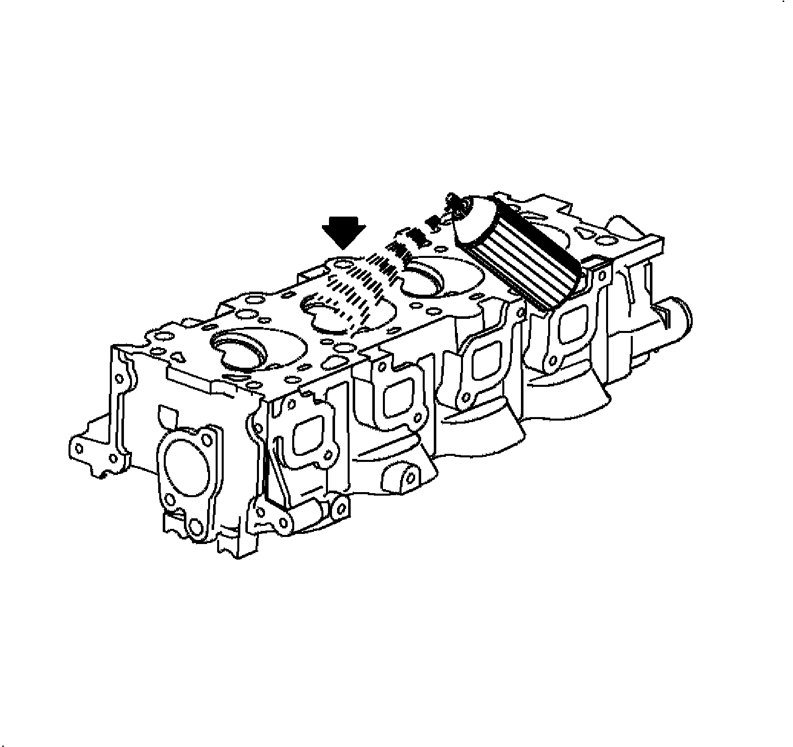
- Inspect the cylinder head
for cracks. Using a dye penetrant, check the combustion chamber intake and
exhaust ports, head surface, and the top of the head for cracks. If cracked,
replace the cylinder head.
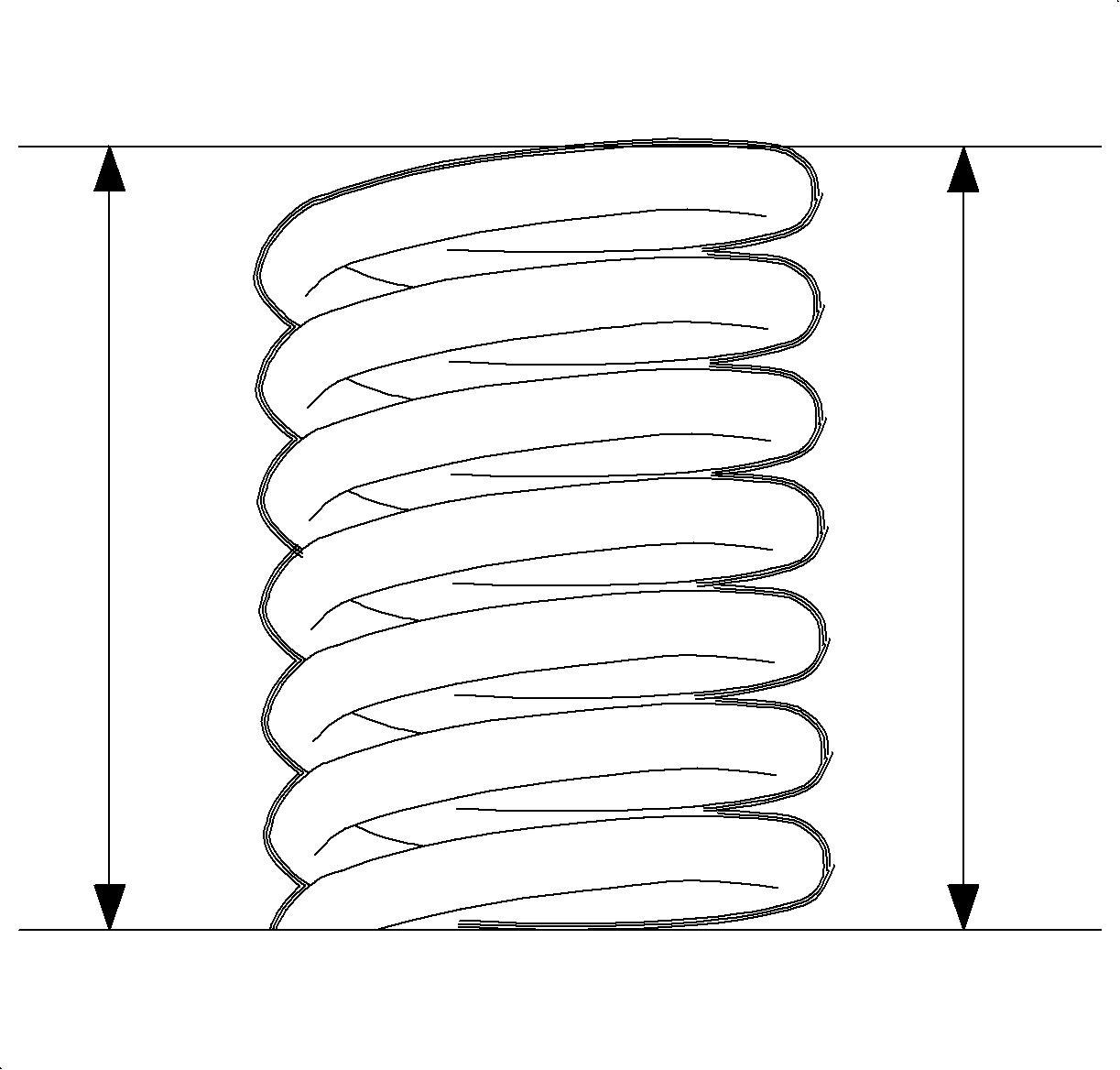
- Inspect the valve spring.
Using calipers, measure the height of the valve spring at 4 locations.
If the spring is bent, replace it.
Specifications
The intake and exhaust valve squareness service limit is 1.58 mm
(0.0622 in) maximum.
- Inspect the valve spring
again. Using calipers, measure the free length of the valve spring. If the
free length is not within specification, replace the valve spring.
Specifications
The free length standard is 39.2 mm (1.543 in) minimum.
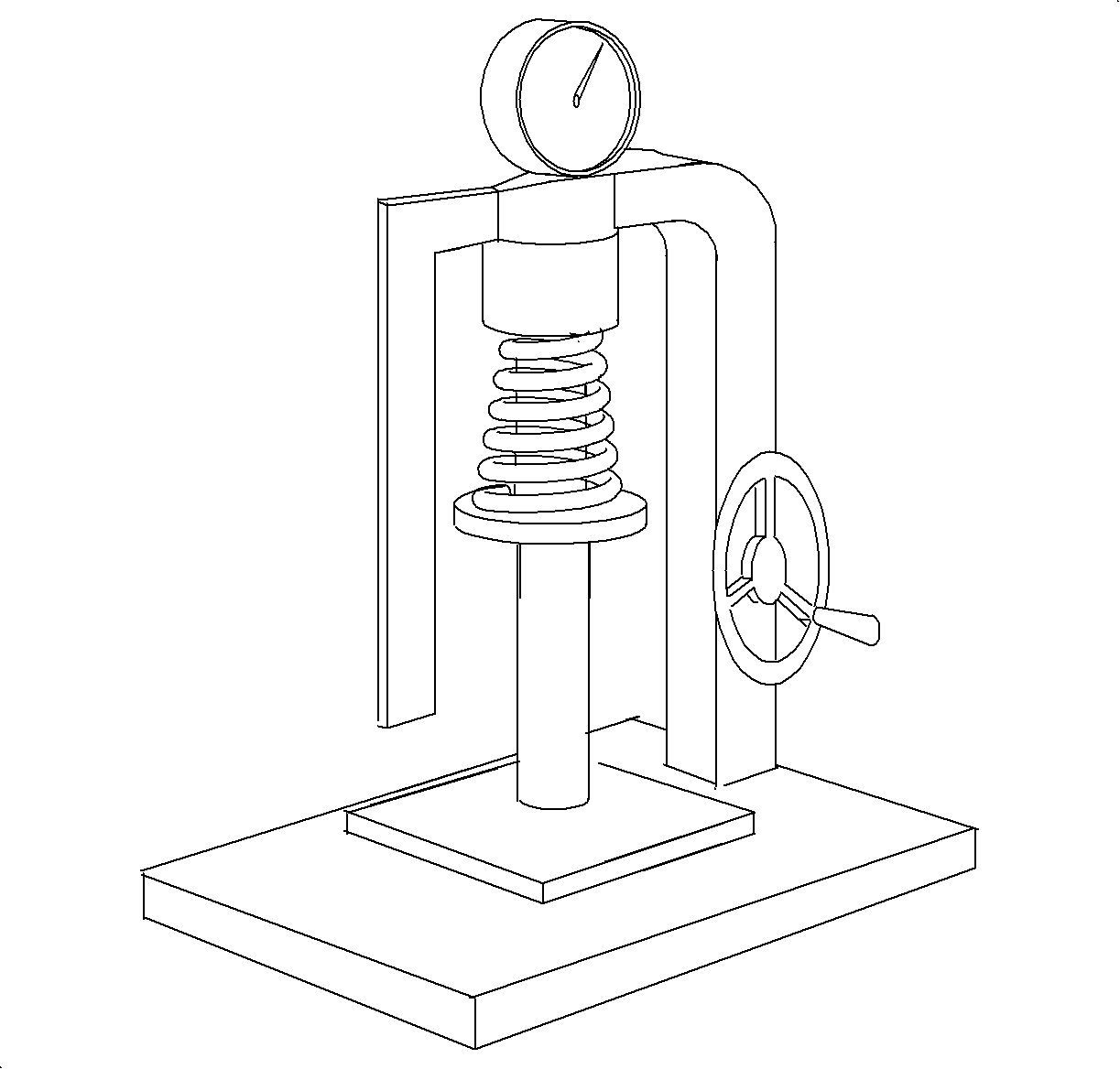
- Using a SA9183NE
, or equivalent, fully collapse the spring 3 times,
then measure the tension of the intake and exhaust valve springs at the specified
installed length. If the installed tension is not as specified, replace the
valve spring.
Specifications
The standard is 34 mm (1.338 in) at 252 N (56.6 lb).
- Clean the valves.
| 11.1. | Using a gasket scraper or wire brush, remove all carbon from the
valve head. |
| 11.2. | Using a wire brush, thoroughly clean the valve. |
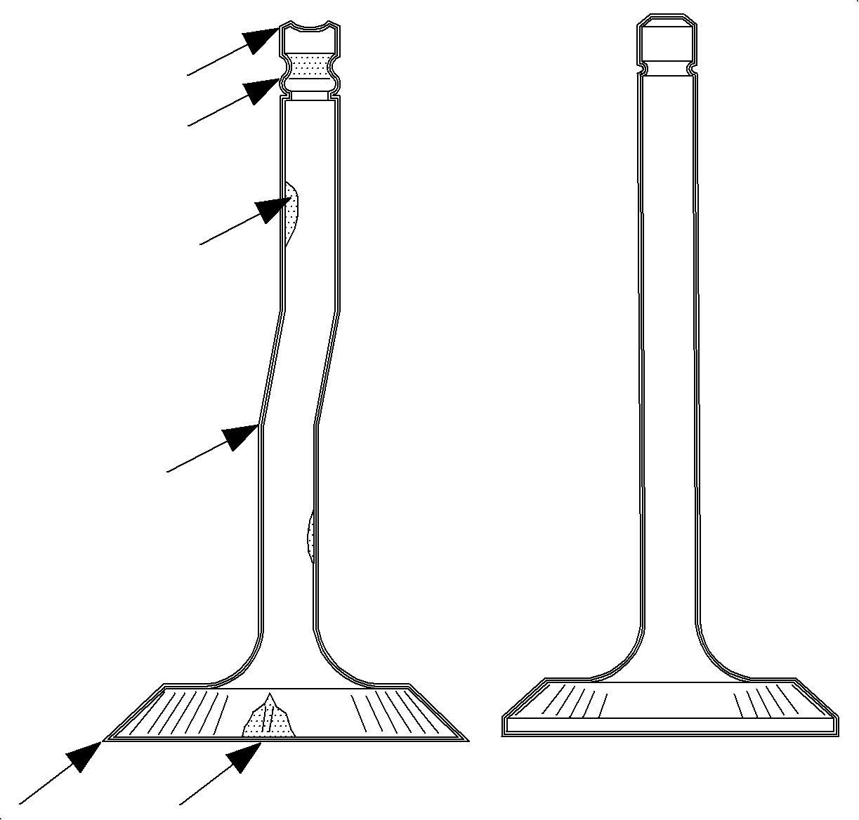
Notice: Small scratches, scores, or scuffs on the valve stem will damage and wear out
the valve stem seal. Always lubricate the valve guide and valve stem before installing
a new valve stem seal. If a valve stem seal is removed after installation, it must
be discarded.
- Inspect the valve stems and guides for wear, scratches,
and burrs.
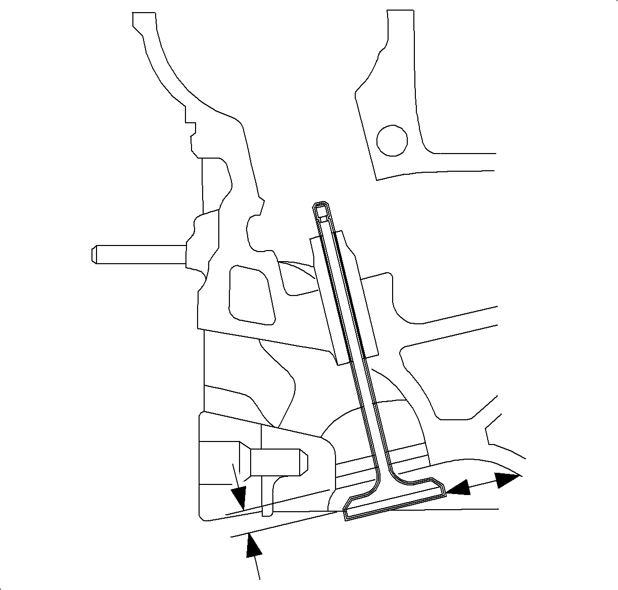
- Replace the spring if
the spring length is less than 34 mm (1.338 in) when subjected
to a compressive force of 252 N (56.6 lbs).
- Perform the following steps to inspect the valve stem-to-valve
guide clearance:
| 14.1. | Clamp the J 8001
on
the exhaust port side of the cylinder head. |
| 14.2. | Locate the indicator so that the movement of the valve stem from
side to side, crosswise to cylinder head, will cause a direct movement of
the indicator stem. |
| 14.3. | Measure the valve head with the valve protruding 10 mm
(0.39 in) from the seat. |
| 14.4. | Drop the valve head about 10 mm (0.39 in) off the
valve seat. |
| 14.5. | Use light pressure to move the stem of the valve from side to
side to obtain a clearance reading. |
| 14.6. | The intake valve clearance should be 0.03-0.057 mm
(0.001-0.0022 in). |
| 14.7. | The exhaust valve clearance should be 0.03-0.057 mm
(0.001-0.0022 in). |
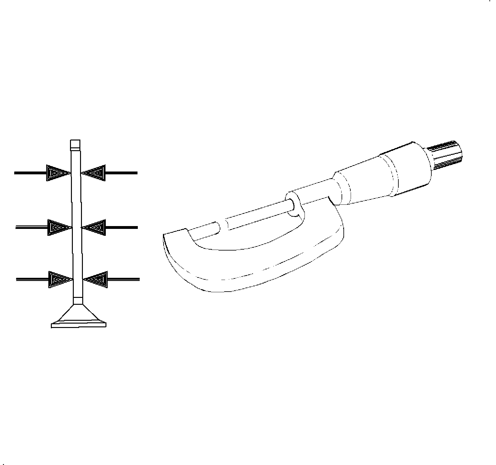
- Measure the valve stem
in 3 locations. If the valve clearance is out of specifications, then
compare the lowest measurement to the specifications below. Replace the valve
if the valve stem is out of specification:
Specifications
| • | The intake valve stem is 5.955-5.970 mm (0.2344-0.235 in). |
| • | The exhaust valve stem is 5.945-5.960 mm (0.234-0.2346 in). |
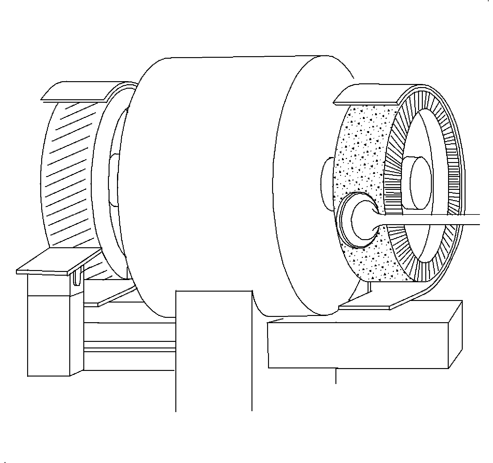
- Ream the valve guide and use an oversized valve if the valve stem
is not within the specification, using J 42096
.


