Removal Procedure
Caution: Ensure that the vehicle is properly supported and squarely positioned. To help avoid personal injury when a vehicle is on a hoist, provide additional support for the vehicle on the opposite end from which the components are being removed.
- Position the vehicle on the hoist and raise the vehicle. Refer to Lifting and Jacking the Vehicle in General Information.
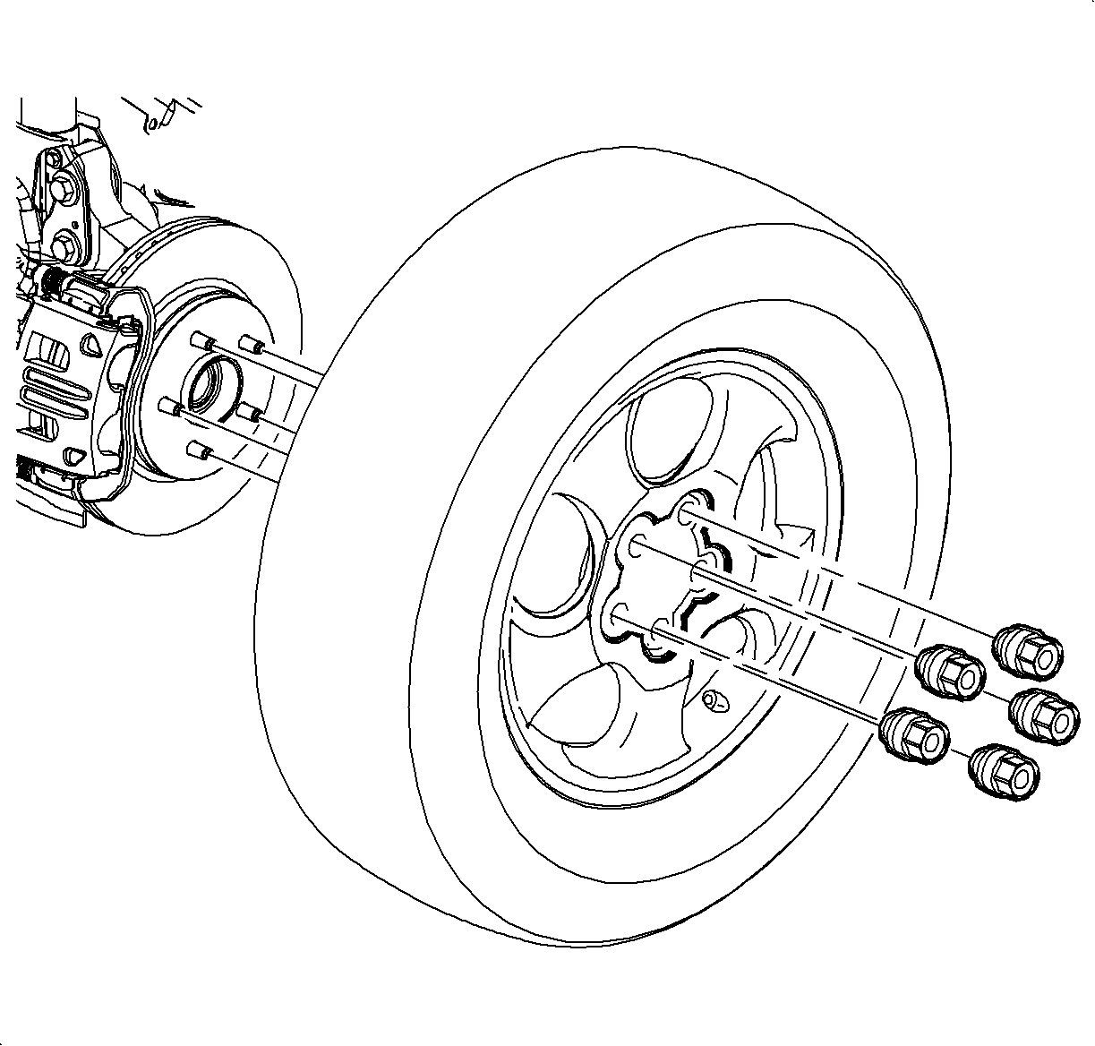
- Remove the left wheel and tire assembly.
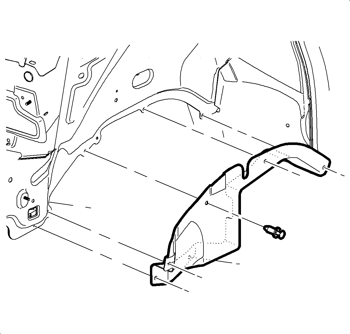
- Remove the left-hand splash shield.
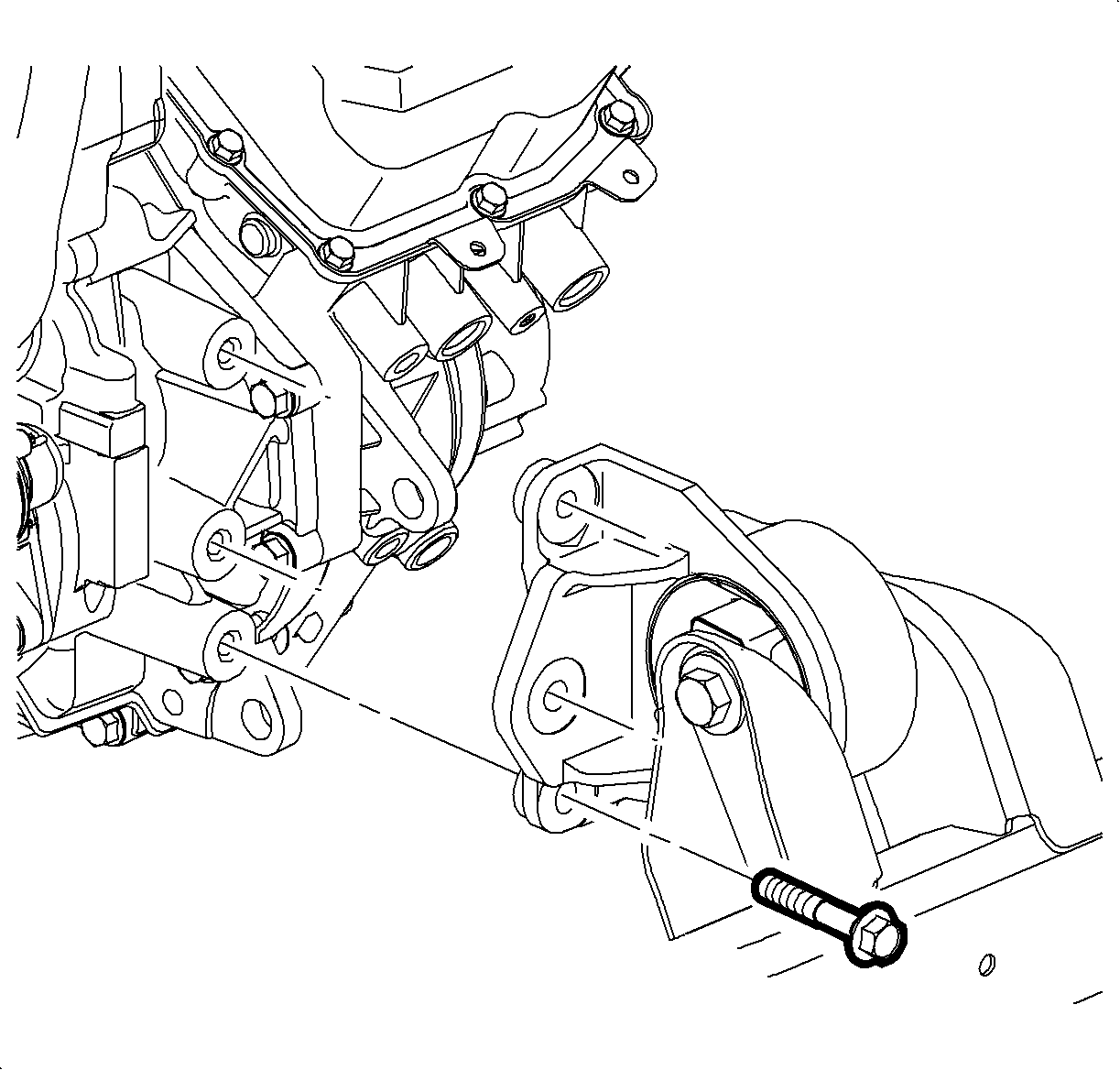
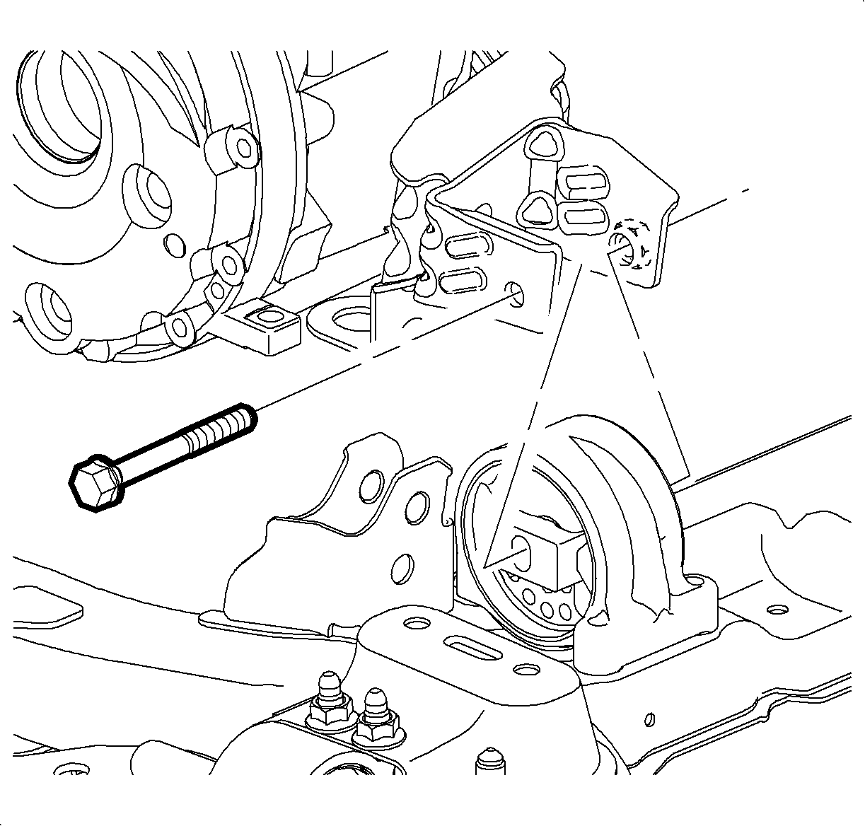
- Remove the front pitch restrictor-to-transaxle bolts.
- Remove the front pitch restrictor through-bolt and the front pitch restrictor.
- Remove the transaxle oil cooler lines from the transaxle.
- Remove the bolts (28) and washers from the control valve body cover (29).
- Remove the control valve body cover.
- Disconnect the solenoid wire connectors.
- Remove the fluid temperature sensor bolt.
- Remove the fluid temperature sensor clamp.
- Remove the fluid temperature sensor and O-ring.
- Remove the wiring harness from the clamps.
- With a twisting motion remove the complete wiring harness assembly.
- Remove the control valve body fluid passage cover bolts, cover, and gasket.
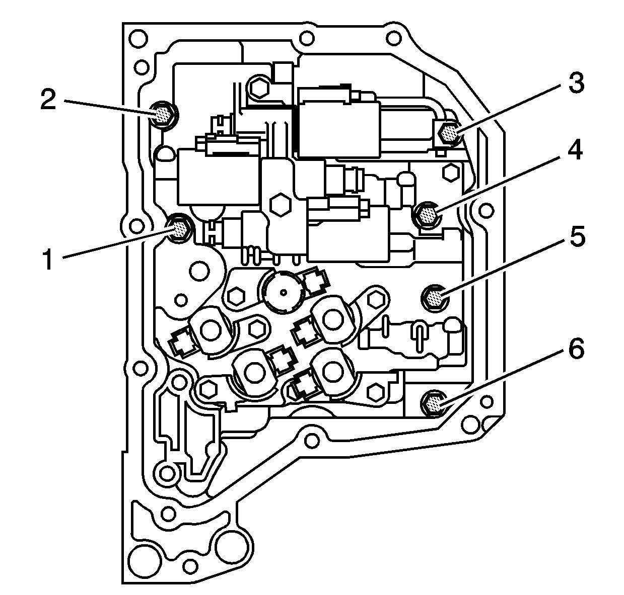
- Remove the valve body assembly to transaxle case bolts (1,2,3,4,5,6).
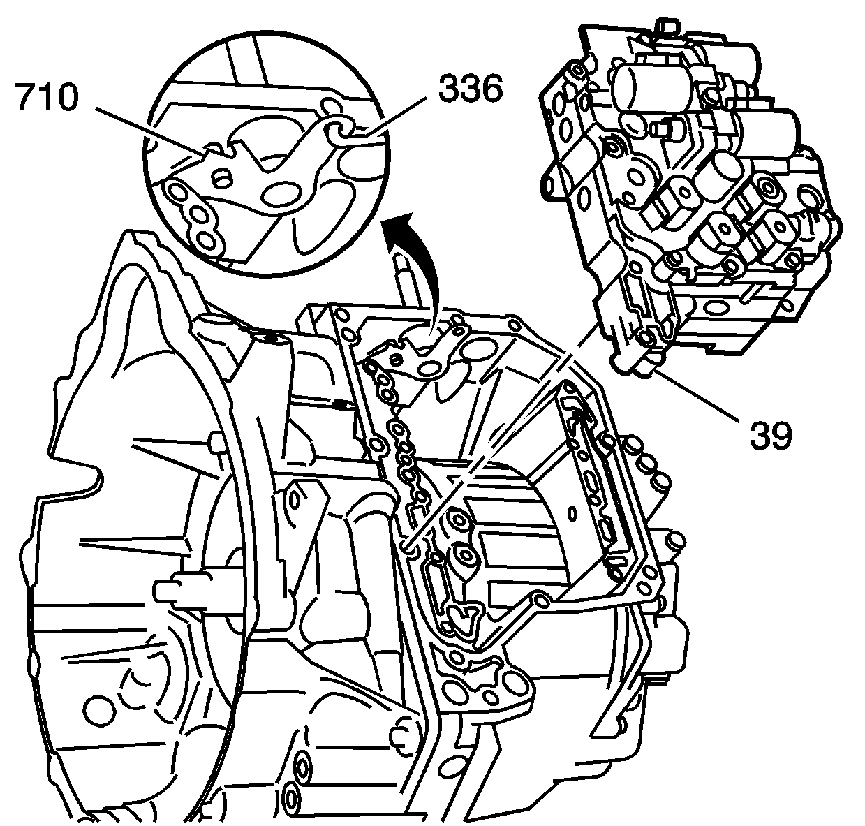
- While holding the valve body assembly, disconnect the manual shift detent lever assembly from the manual valve link.
- Move the detent lever assembly clockwise for ease of removing the manual valve.
- Remove the valve body assembly from the vehicle.
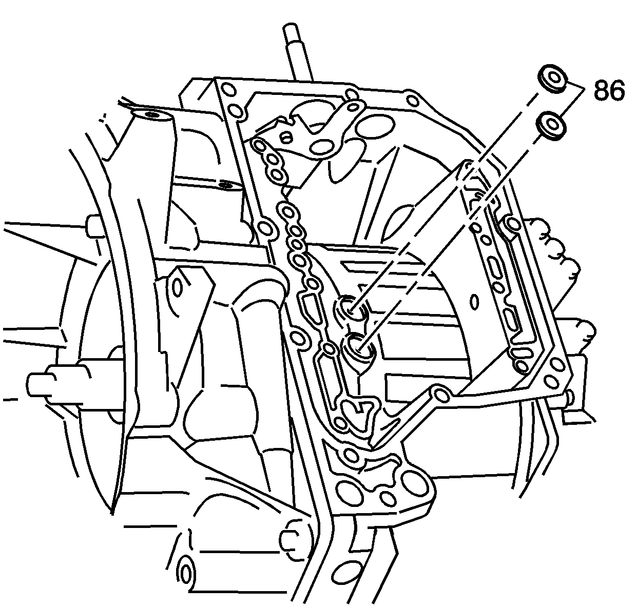
- Remove the case fluid passage seals and discard.
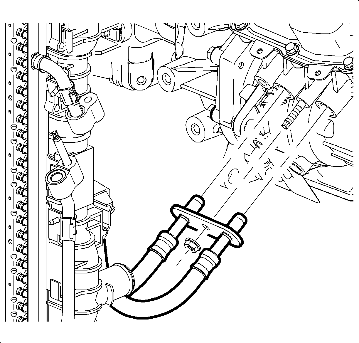
| 6.1. | Place a drain pan or suitable container under vehicle. |
| 6.2. | Remove the transaxle oil cooler line assembly nut from the transaxle. |
| 6.3. | Remove the transaxle oil cooler lines from the vehicle |
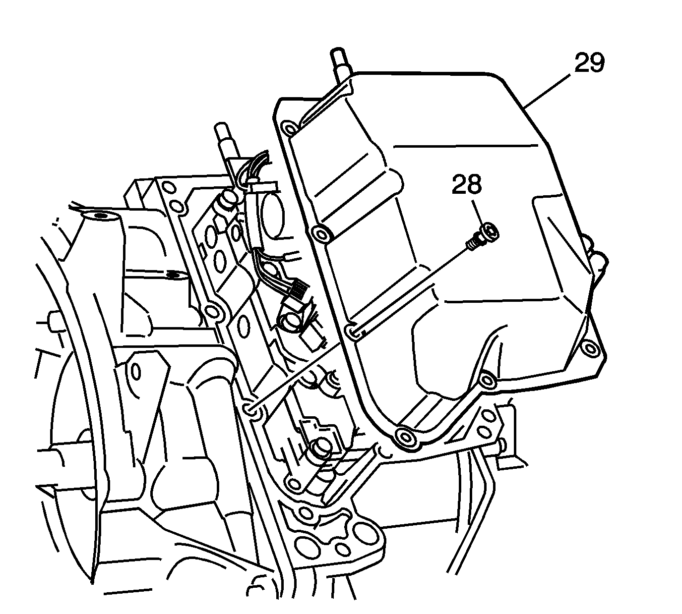
Important: Do not damage the transaxle control valve body cover, case, or sealing surfaces.
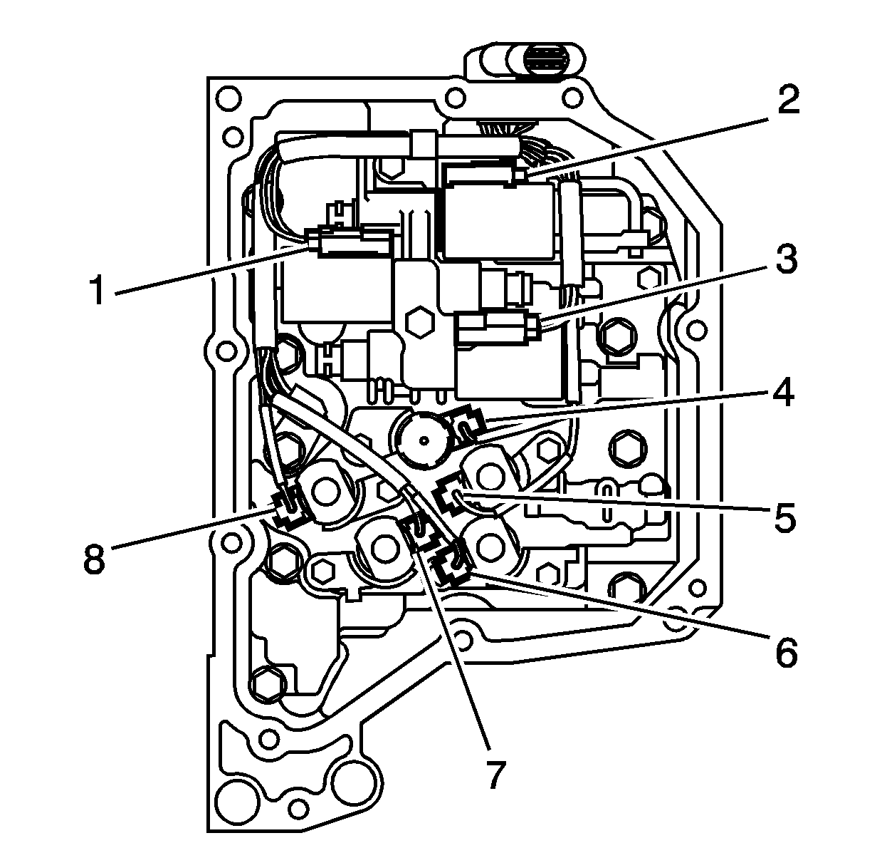
Important: Do not bent the solenoid wire connector pins.
| 9.1. | Blue (1) |
| 9.2. | Black (2) |
| 9.3. | Green (3) |
| 9.4. | Black (4) |
| 9.5. | Blue (5) |
| 9.6. | Gray (6) |
| 9.7. | Green (7) |
| 9.8. | Gray (8) |
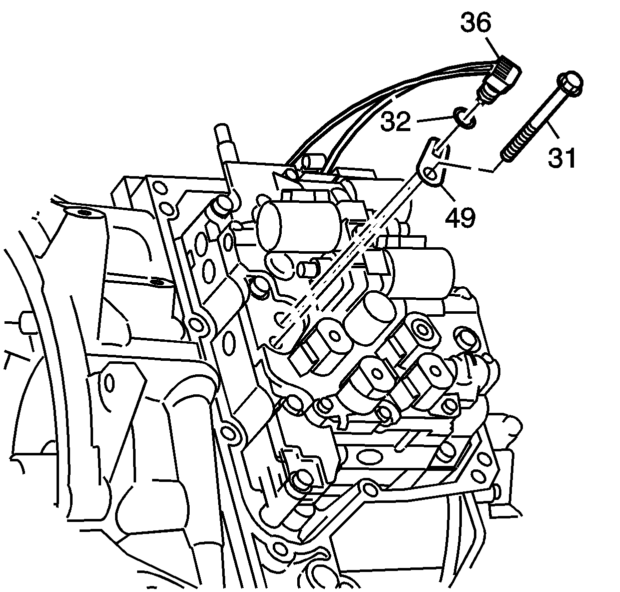
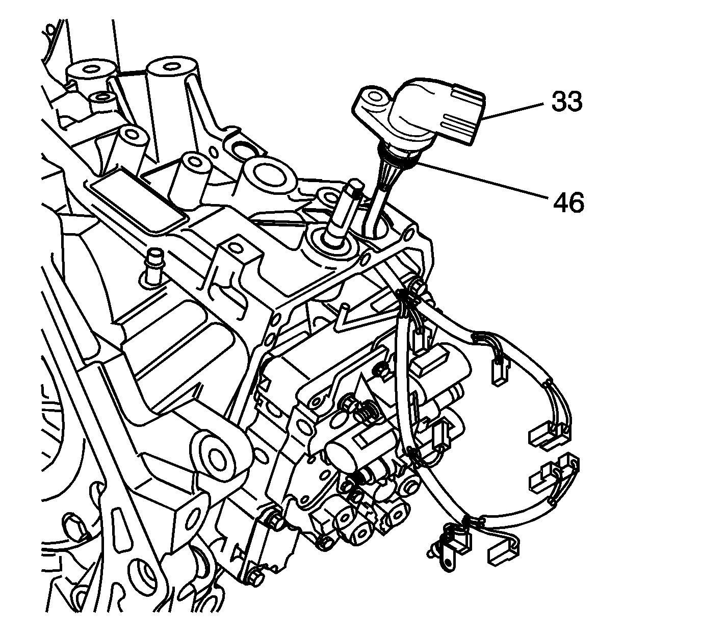
Important: Do not break the wiring harness connectors or the fluid temperature sensor. Remove the harness only for TFT replacement or damaged wiring.
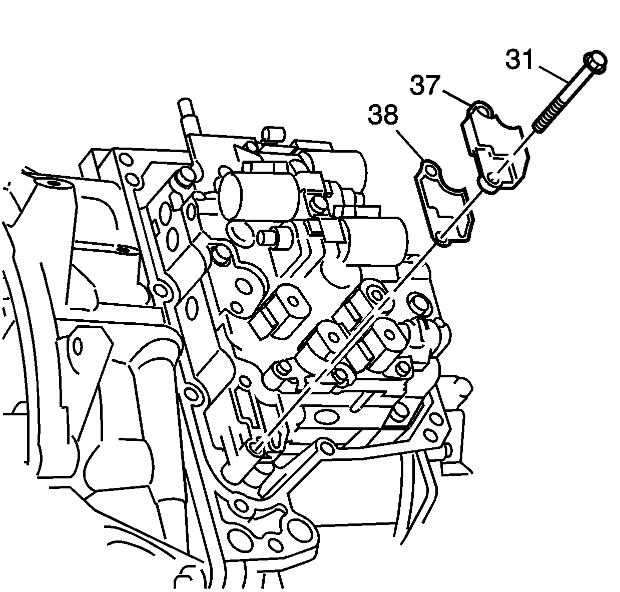
Important: Place the transaxle in neutral (N) position.
Installation Procedure
- Install new case fluid passage seals onto the transaxle case.
- Shift transaxle into neutral (N) position.
- While holding the valve body assembly, connect the manual shift detent lever assembly to the manual valve link.
- Install the valve body assembly-to-transaxle case bolts (34,35,47) and hand tighten.
- Tighten the valve body assembly-to-transaxle case bolts in the sequence shown.
- Install a new control valve body fluid passage cover gasket.
- Install a new control valve body fluid passage cover.
- Install the M6 X 1.0 X 50 mm control valve body bolts.
- Install a new O-ring seal onto the wiring harness.
- Install the wiring harness.
- Install the new O-ring into the groove of the fluid temperature sensor.
- Install the fluid temperature sensor into the valve body.
- Install the fluid temperature sensor clamp.
- Install the fluid temperature sensor bolt.
- Connect the solenoid harness connectors in the following order:
- Clean and inspect the valve body cover and transaxle gasket surfaces for gasket material and debris.
- Install RTV sealer Saturn P/N 89020326 onto the control valve body cover.
- Install the control valve body cover onto the transaxle case.
- Apply threadlocker Saturn P/N 21485277 to the bolts. Hand tighten the bolts.
- Tighten the valve body cover bolts using the sequence shown.
- Install the transaxle cooler lines to the transaxle.
- Install the transaxle oil cooler line assembly nut.
- Install the front pitch restrictor through-bolt.
- Install the front pitch restrictor to the transaxle.
- Install the left-hand splash shield.
- Install splash shield push pins.
- Install the left wheel and tire assembly.
- Install the wheel nuts and tighten in a crisscross pattern.
- Install a new front axle to knuckle nut and tighten.
- Lower the vehicle.
- Add fluid to the transaxle as necessary. Refer to the Transmission Fluid Replacement procedure located in this service manual.
- Start the engine and check for leaks.
- Reset the TAP values. Refer to Transmission Adaptive Functions .

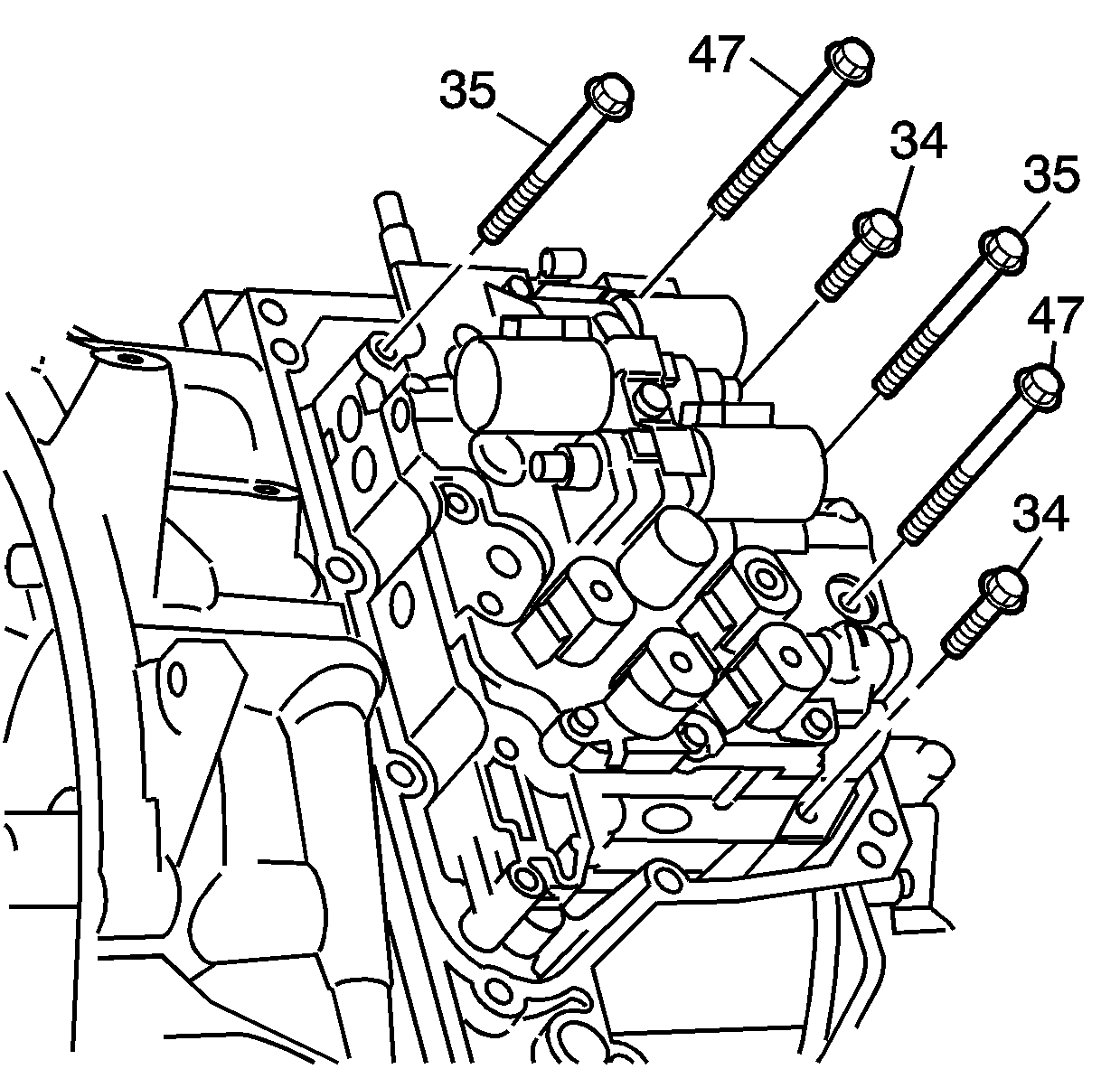
Notice: Refer to Fastener Notice in the Preface section.
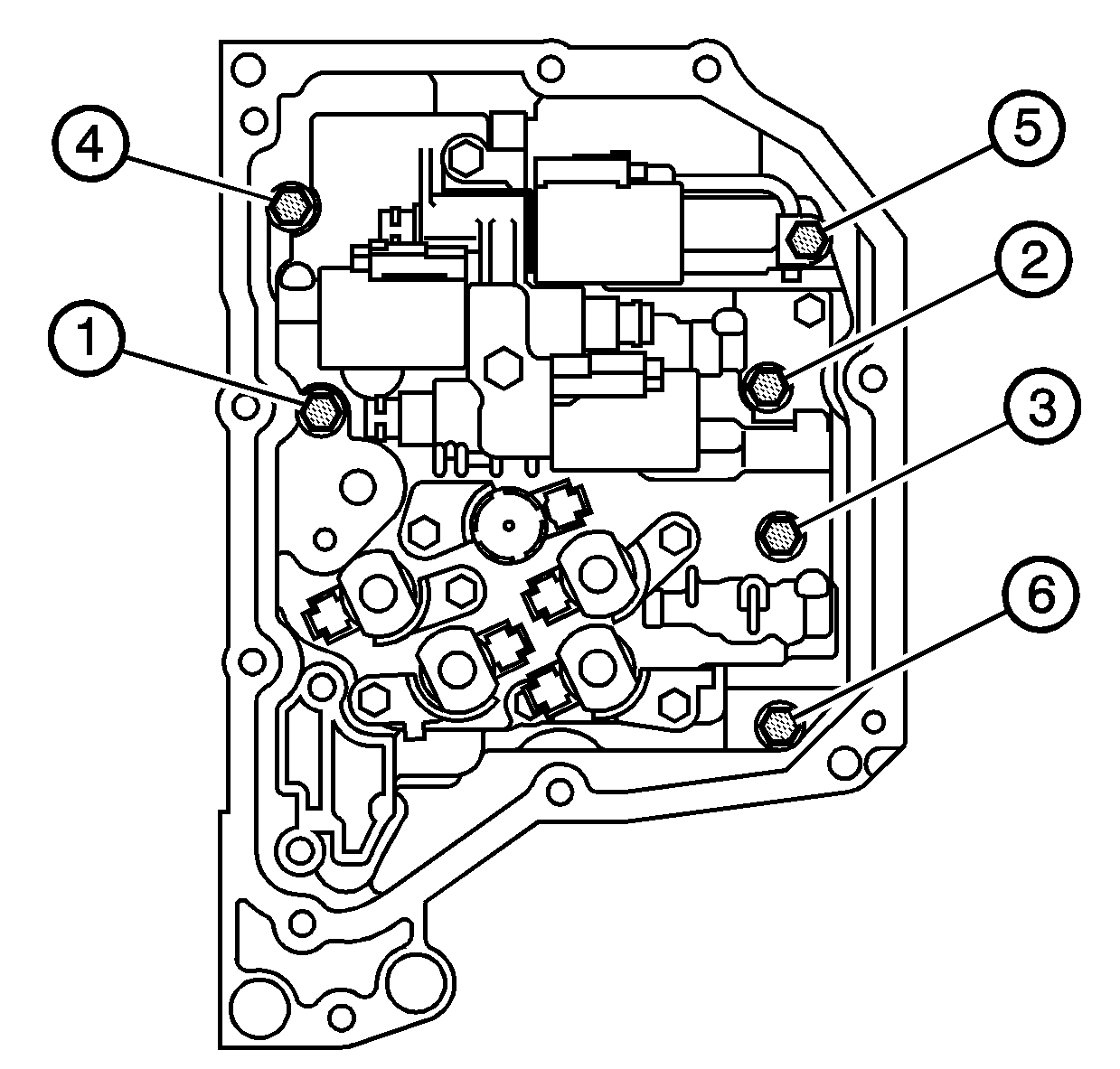
Tighten
Tighten the bolts to 10 N·m(89 lb-in).

Tighten
Tighten the bolts to 10 N·m(89 lb-in).
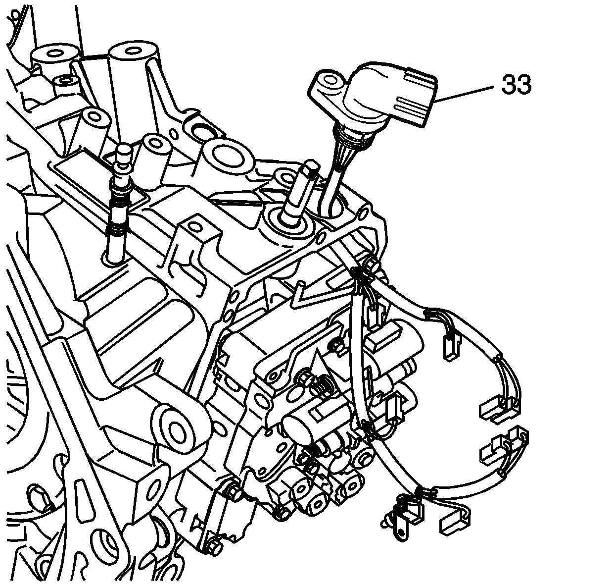
Important: Apply transaxle fluid to the new fluid temperature sensor O-ring.

Important: Apply transaxle fluid to the new O-ring
Tighten
Tighten the bolt to 10 N·m(89 lb-in).

Important: Do not bend solenoid wire connector pins.
| 15.1. | Blue (1) |
| 15.2. | Black (2) |
| 15.3. | Green (3) |
| 15.4. | Black (4) |
| 15.5. | Blue (5) |
| 15.6. | Gray (6) |
| 15.7. | Green (7) |
| 15.8. | Gray (8) |
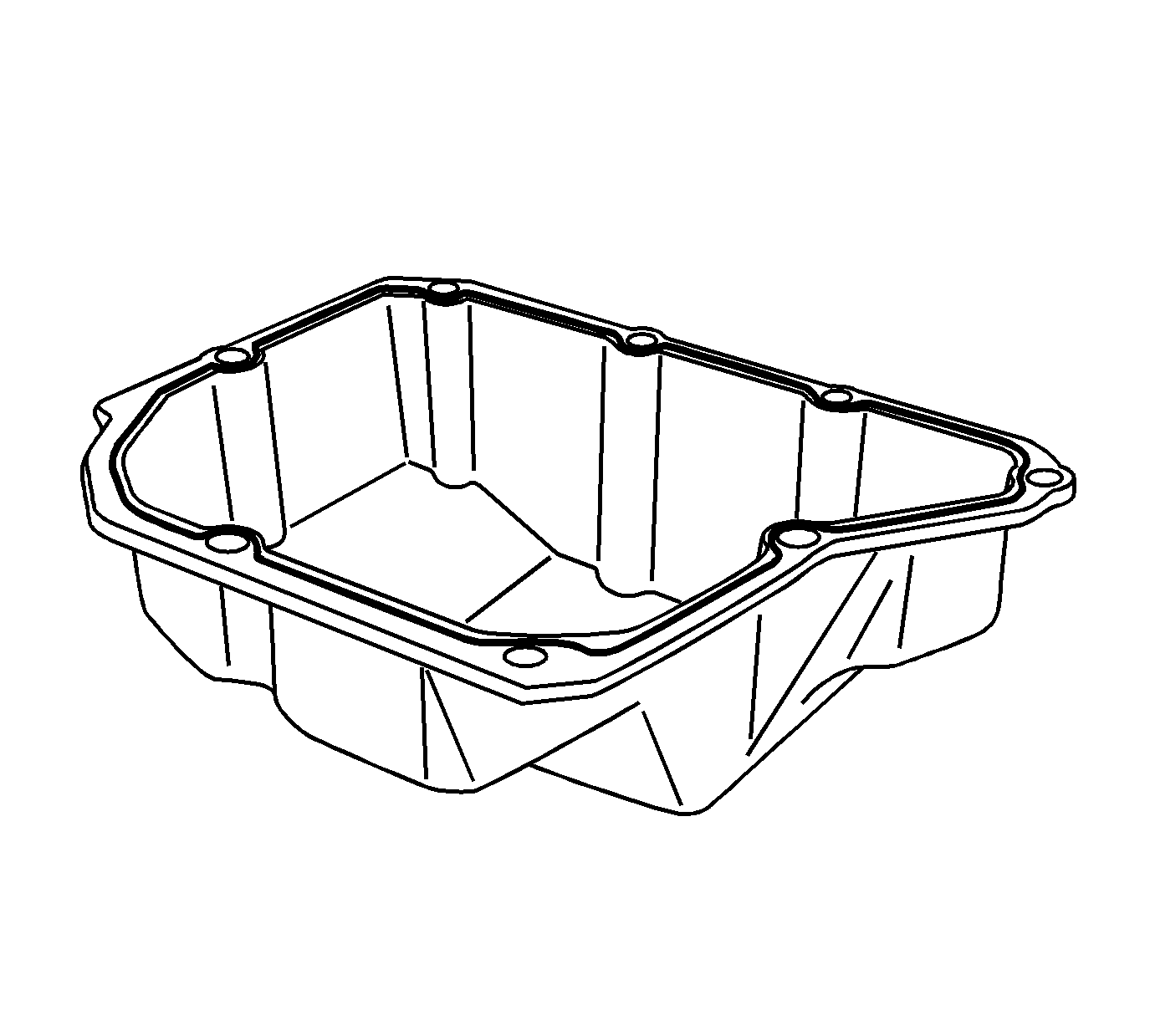
Important: The cover and transaxle must be free of dirt, gasket material and debris in order to seal properly.

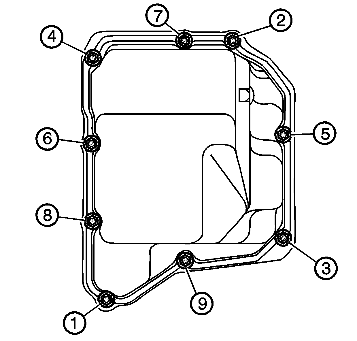
Tighten
Tighten the bolts to 13 N·m(10 lb-ft)

Tighten
Tighten the transaxle oil cooler line nut to 7 N·m(62 lb-in)

Tighten
Tighten the front pitch restrictor through-bolt to 110 N·m(81 lb-ft)

Tighten
Tighten the front pitch restrictor bolts to 50 N·m(37 lb-ft)


Tighten
Tighten the wheel nuts to 125 N·m(92 lb-ft)
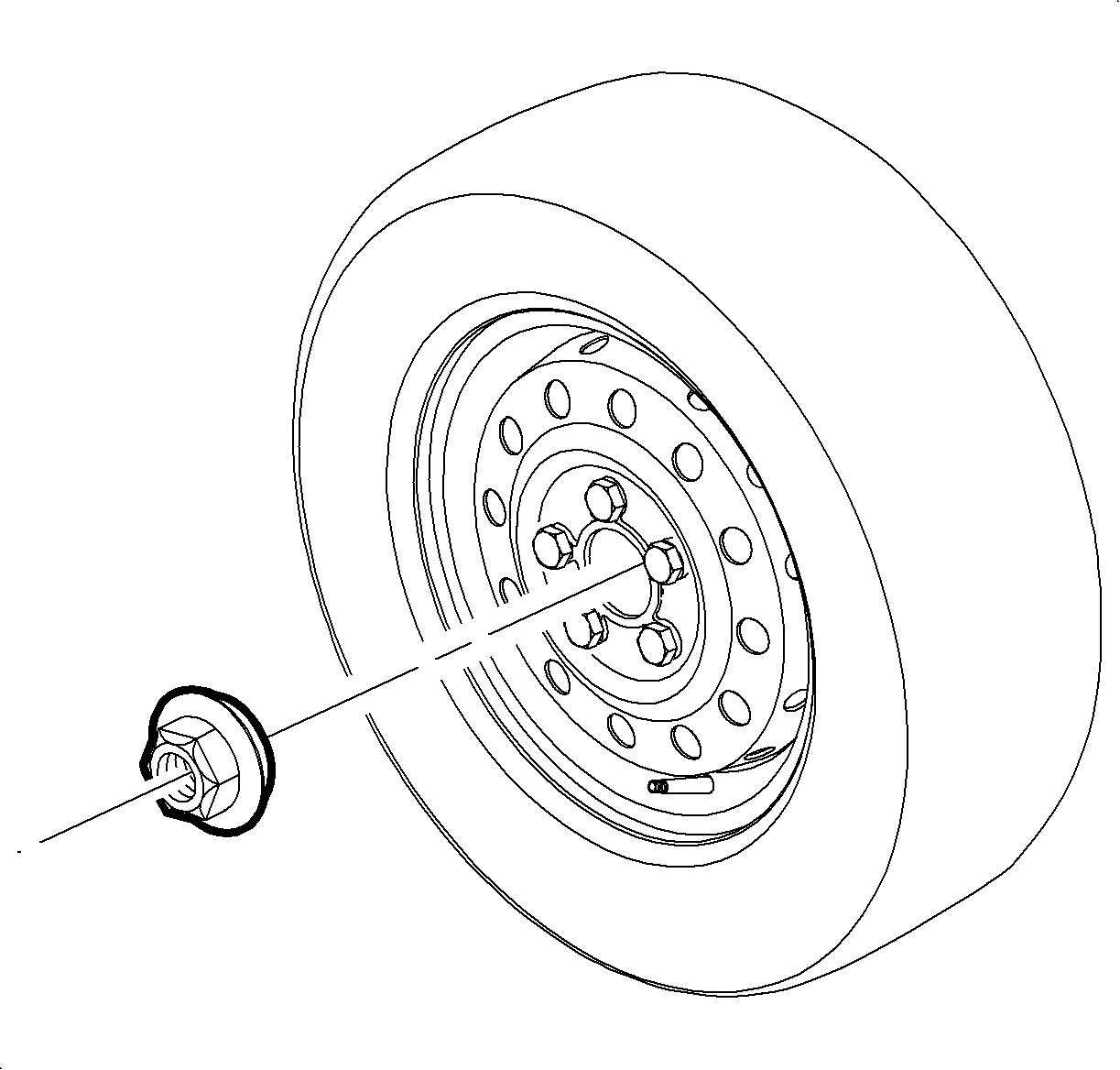
Tighten
Tighten the front axle shaft hub nut to 205 N·m(151 lb-ft)
Notice: Saturn automatic transaxle fluid (ATF), P/N 21005966 and P/N 21019223, is not compatible with this transaxle. If Saturn ATF is used, transaxle damage will result. This transaxle uses Saturn T-IV fluid P/N 22689186.
Important: It is recommended that transmission adaptive pressure (TAP) information be reset.
Resetting the TAP values using a scan tool will erase all learned values in all cells. As a result, The ECM, PCM or TCM will need to relearn TAP values. Transmission performance may be affected as new TAP values are learned.