For 1990-2009 cars only
Tools Required
| • | J 44851 Pinion Seal Installer |
| • | J 44873 Pinion Flange Holder and Remover |
Removal Procedure
- Raise and support the vehicle. Refer to Lifting and Jacking the Vehicle .
- Index mark the propeller shaft at the power take-off unit (PTU) output flange and at the rear drive module input flange.
- Place an adjustable support at the front and the rear of the propeller shaft.
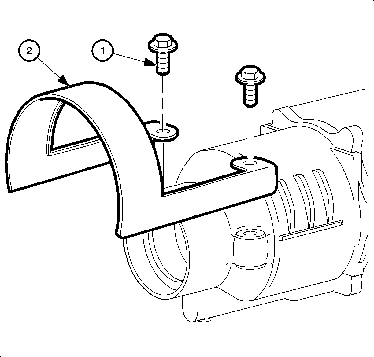
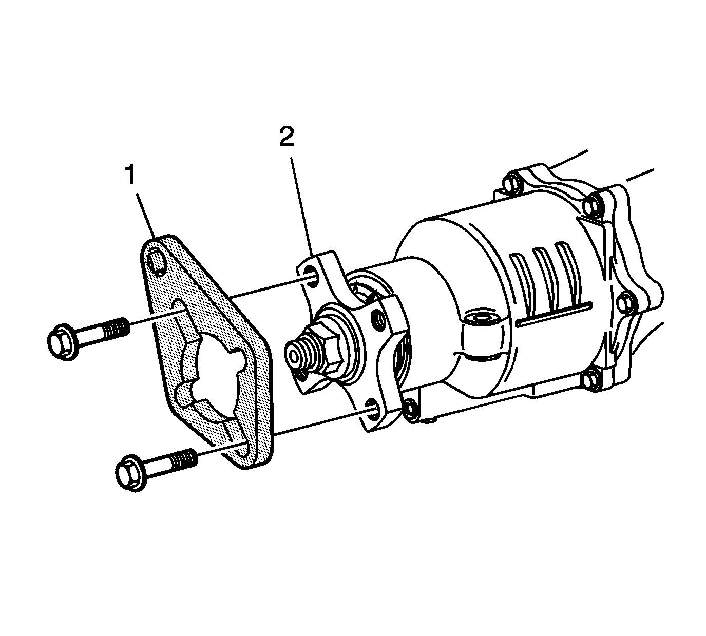
- Remove the rear drive module (RDM) propeller shaft guard (2) mounting bolts (1)
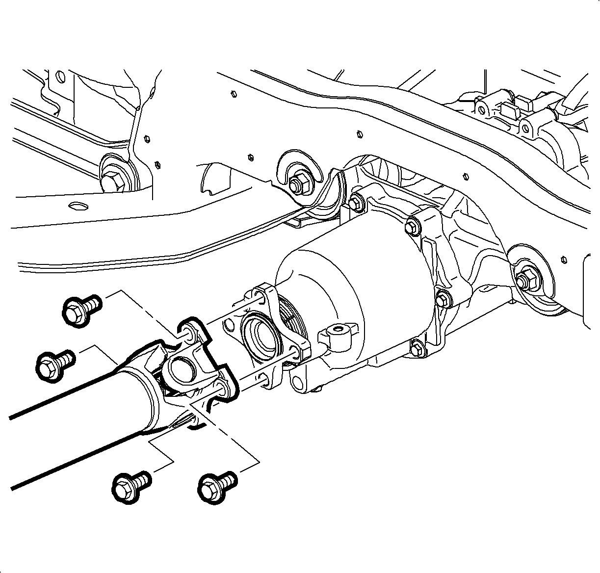
- Remove the bolts securing the propeller shaft to the RDM flange.
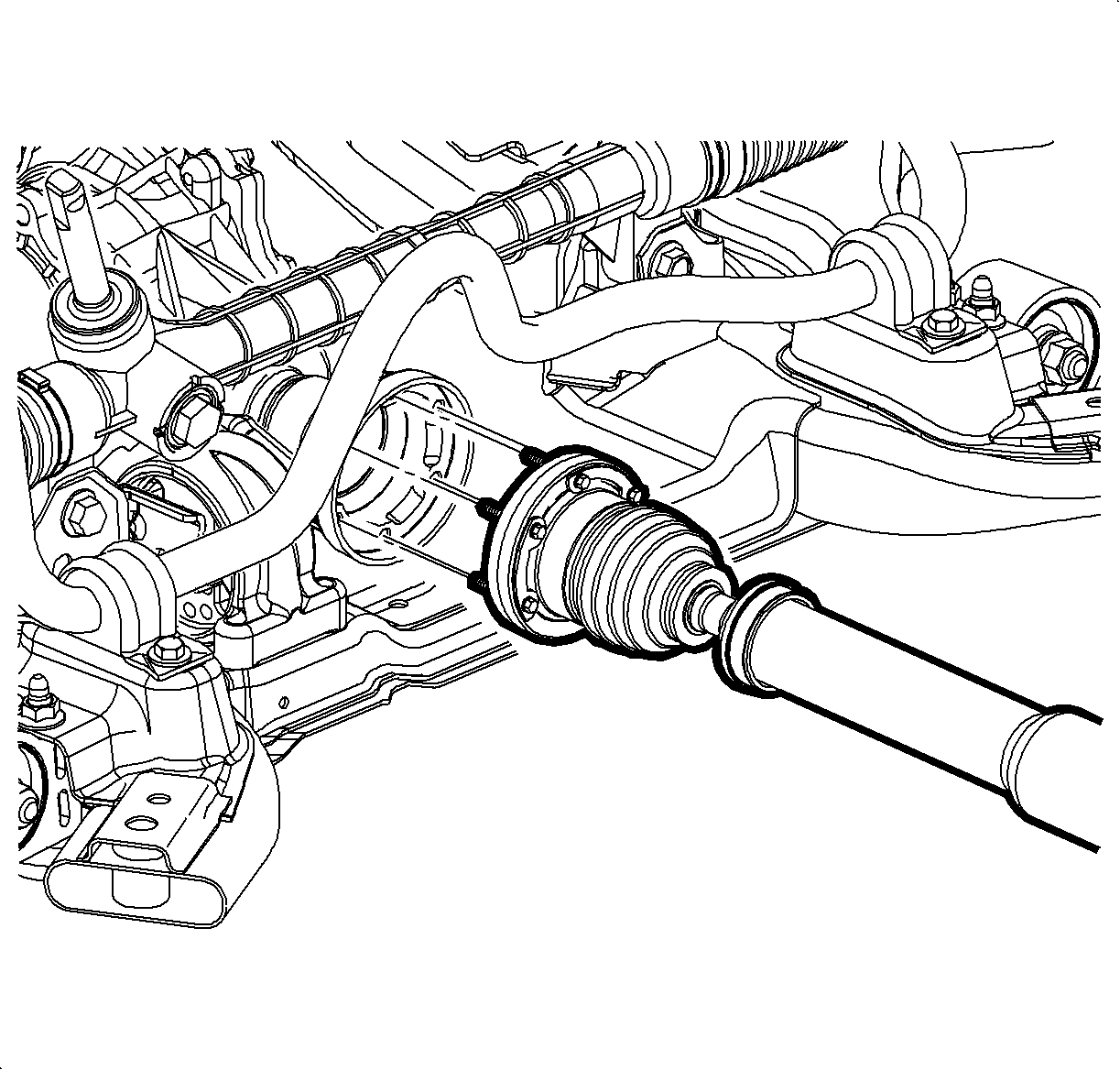
- Remove the bolts securing the propeller shaft to the PTU.
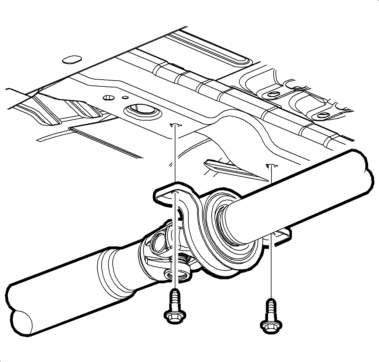
- Remove the bolts securing the support bearing to the vehicle underbody.
- Remove the propeller shaft from the vehicle.
- Install the J 44873 (1) to the pinion flange (2).
- While holding the J 44873 with a breaker bar, loosen the pinion flange nut.
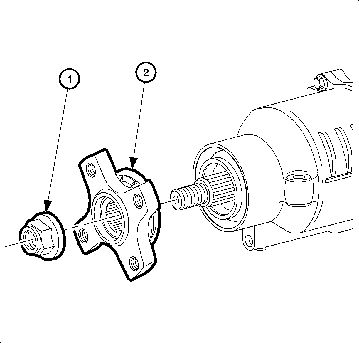
- Remove and discard the pinion flange nut (1).
- Remove the flange (2).
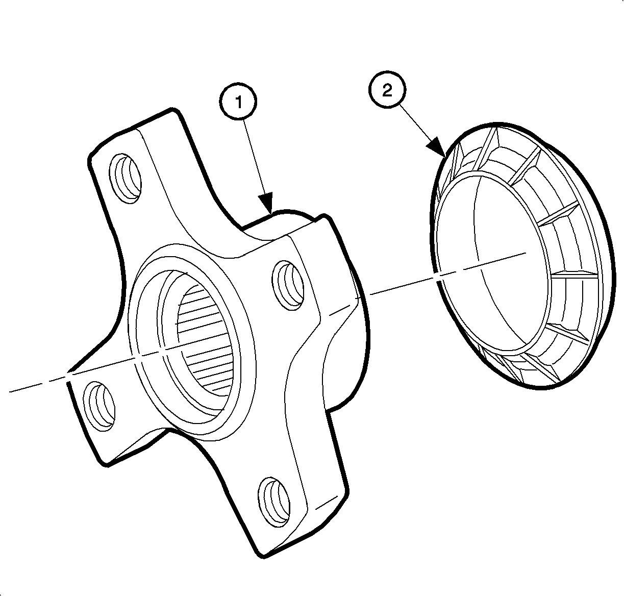
- Remove the dust deflector (2) from the pinion flange (1).
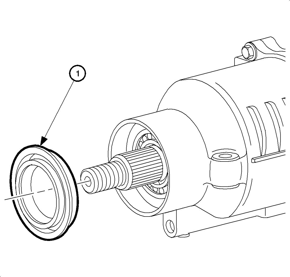
- Remove and discard the pinion oil seal (1).
Installation Procedure
- Thoroughly clean the pinion oil seal mounting surface of the RDM housing (1).
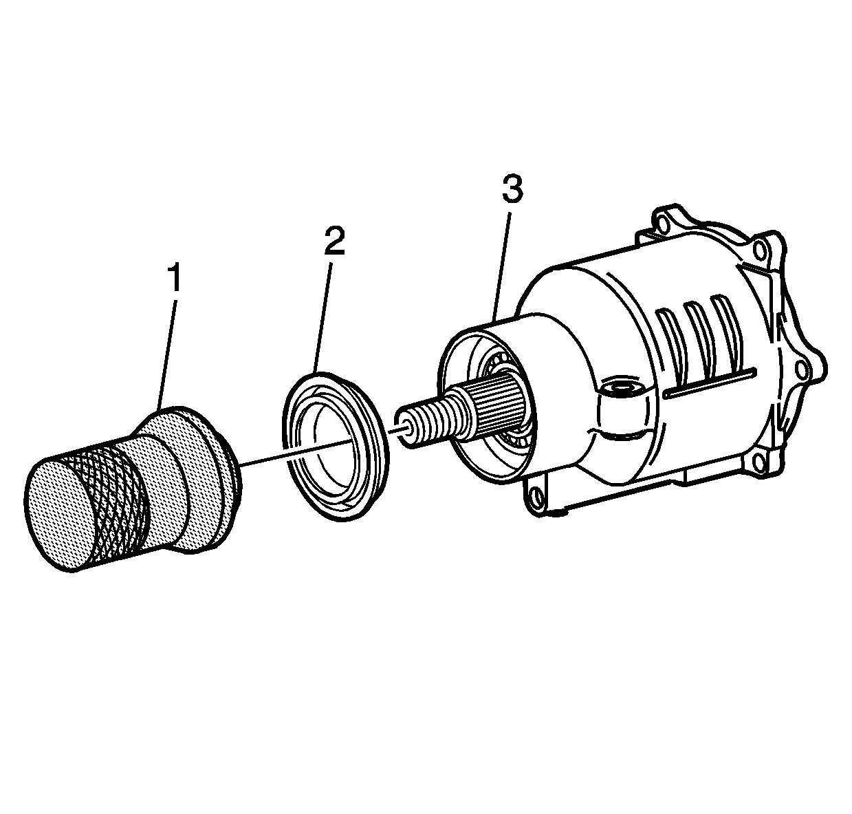
- Using the J 44851 , install a new pinion oil seal to the RDM.
- Ensure that the seal flange seats squarely against the face of the RDM.
- Install the dust deflector (2) to the drive pinion flange (1).
- Install the pinion flange (2) and nut (1) to the RDM.
- Install the J 44873 (1) to the pinion flange (2).
- While holding the pinion flange stationary with a breaker bar on the J 44873 , tighten the pinion flange nut.
- Remove the J 44873 from pinion flange.
- Install the propeller shaft to the vehicle using support stands to assist in positioning the propeller shaft.
- Hand install the support bearing retainer bolts to the vehicle underbody.
- Align the reference marks on the propeller shaft and the PTU output flange.
- Install the bolts to the propeller shaft and the PTU flange.
- Align the reference marks on the propeller shaft and the RDM pinion flange.
- Install the bolts to the propeller shaft and the pinion flange.
- Remove the support stands.
- Install the propeller shaft guard to the RDM.
- Install the bolts to the propeller shaft guard.
- Inspect the RDM fluid level. Refer to Rear Axle Lubricant Level Inspection .
- Lower the vehicle.

Notice: Refer to Fastener Notice in the Preface section.


Tighten
Tighten the nut to 203 N·m (150 lb ft).


Tighten
Tighten the bolts to 25 N·m (18 lb ft).

Tighten
Tighten the bolts to 50 N·m (37 lb ft).

Tighten
Tighten the bolts to 25 N·m (18 lb ft).
