| Table 1: | Device Power Moding |
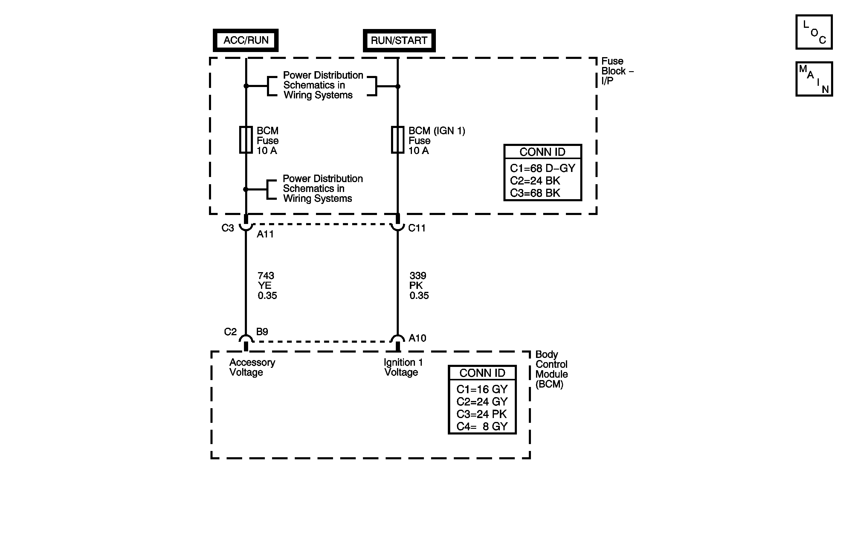
Circuit Description
Normal vehicle class 2 communication will not commence until the system power mode has been identified. The BCM communicates the system power mode to all the modules connected to the class 2 serial data circuit. The BCM monitors the state of the ignition 1 voltage circuit, accessory voltage circuit and the engine run flag (ERF) in order to determine the present system power mode. The ERF is a serial data message from the engine controller.
Conditions for Running the DTC
Anytime the BCM receives an input or message. The ignition is in the START position.
Conditions for Setting the DTC
The BCM has detected the ignition 1 voltage circuit is open or shorted to ground for greater than 1.2 seconds when the accessory voltage circuit is high and the engine run flag is true.
Action Taken When the DTC Sets
| • | There is no cluster illumination during bulb check. |
| • | DTC B1372 is set in the BCM. |
| • | The malfunction indicator lamp (MIL) is illuminated. |
| • | BCM (IGN 1) fuse will open with a short to ground present. |
Conditions for Clearing the MIL/DTC
| • | A current DTC clears and the MIL is turned OFF when the fault is no longer present. |
| • | A history DTC clears when the module ignition cycle counter reaches the reset threshold, without a repeat of the fault. |
Diagnostic Aids
Refer to Testing for Intermittent Conditions and Poor Connections in Wiring Systems.
Key Position | Ignition Accessory/Run | Ignition 1 Run/Crank |
|---|---|---|
RUN | Active | Active |
CRANK | Inactive | Active |
ACCY | Active | Inactive |
OFF | Inactive | Inactive |
Test Description
The numbers below refer to the step numbers on the diagnostic table.
Step | Action | Yes | No |
|---|---|---|---|
Schematic Reference: Body Control System Schematics Connector End View Reference: Master Electrical Component List in Wiring Systems | |||
1 | Did you perform the Diagnostic System Check for the system exhibiting the symptom? | Go to Step 2 | Go to Control Module References for the applicable Diagnostic System Check |
2 |
Does the Ignition 1 Input parameter display High? | Refer to Diagnostic Aids | Go to Step 3 |
Does the test lamp illuminate? | Go to Step 4 | Go to Step 5 | |
4 | Inspect for poor connections and terminal tension at the harness connector of the BCM. Refer to Testing for Intermittent Conditions and Poor Connections and Connector Repairs in Wiring Systems. Did you find and correct the condition? | Go to Step 7 | Go to Step 6 |
5 | Repair the inactive ignition 1 voltage signal circuit for an open, high resistance or a short to ground. Refer to Circuit Testing and Wiring Repairs in Wiring Systems. Did you complete the repair? | Go to Step 7 | -- |
6 |
Important:: Perform the programming or set up procedure for the BCM. Refer to Body Control Module (BCM) Programming/RPO Configuration . Replace the BCM. Refer to Body Control Module Replacement for applicable replacement procedure. Did you complete the replacement? | Go to Step 7 | -- |
7 |
Does the DTC reset? | Go to Step 2 | System OK |
