Tools Required
J 44337 Build Plate Assembly
- Position the drive and driven pulley assemblies on the J 44337 .
- Inspect the belt contact areas on the drive and driven pulley assemblies. The surfaces should be smooth and free from any scoring.
- Position the U-shaped ring of the J 44337 on the driven pulley assembly.
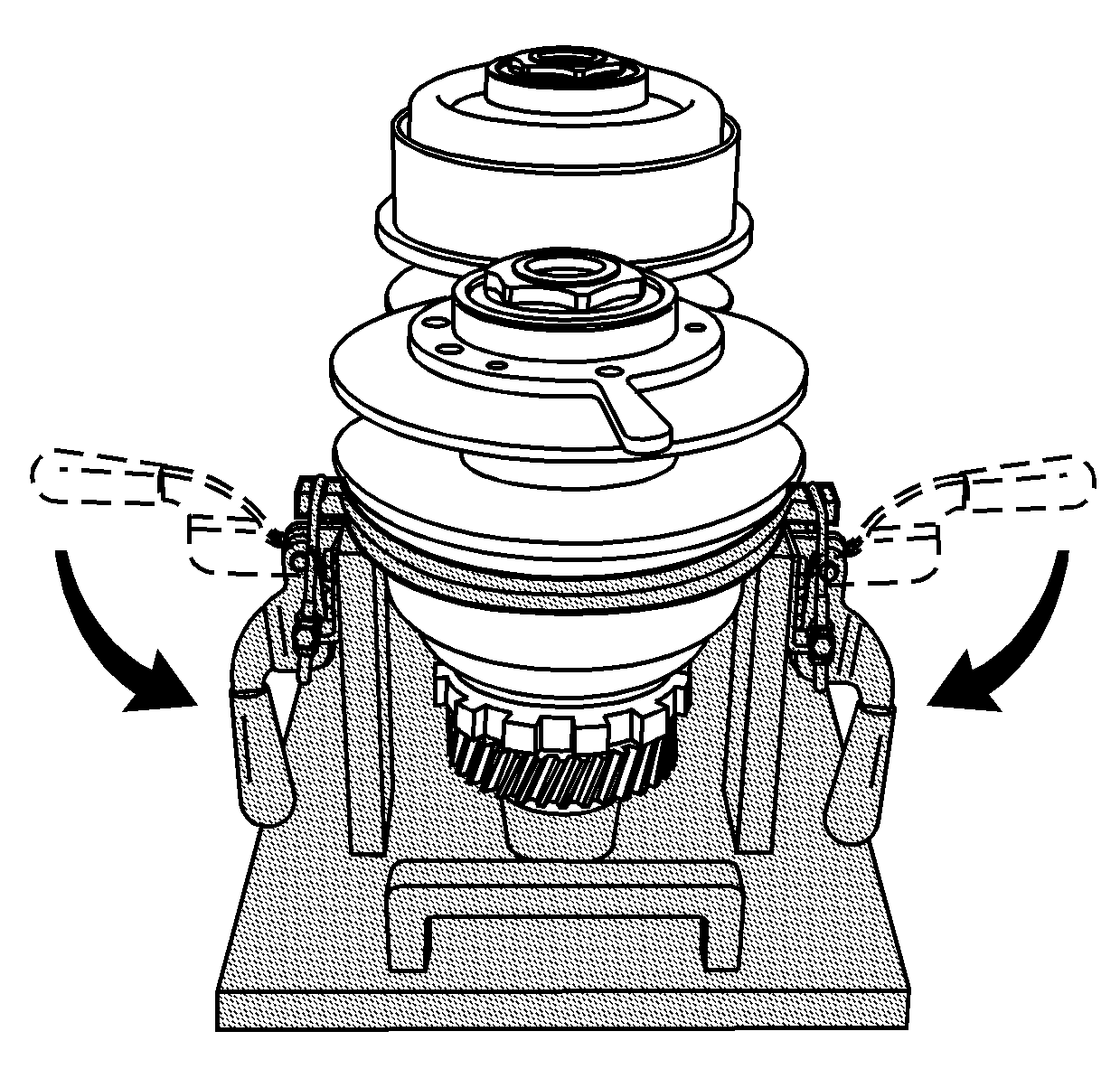
- Position the clamp U-bolts of the J 44337 in the slotted grooves of the U-shaped ring.
- Using both hands, push down on the clamp handles with equal pressure in order to compress the driven pulley assembly.
- Inspect the belt assembly for sharp dents on the sides of the ringsets.
- Inspect the belt ringsets for burrs.
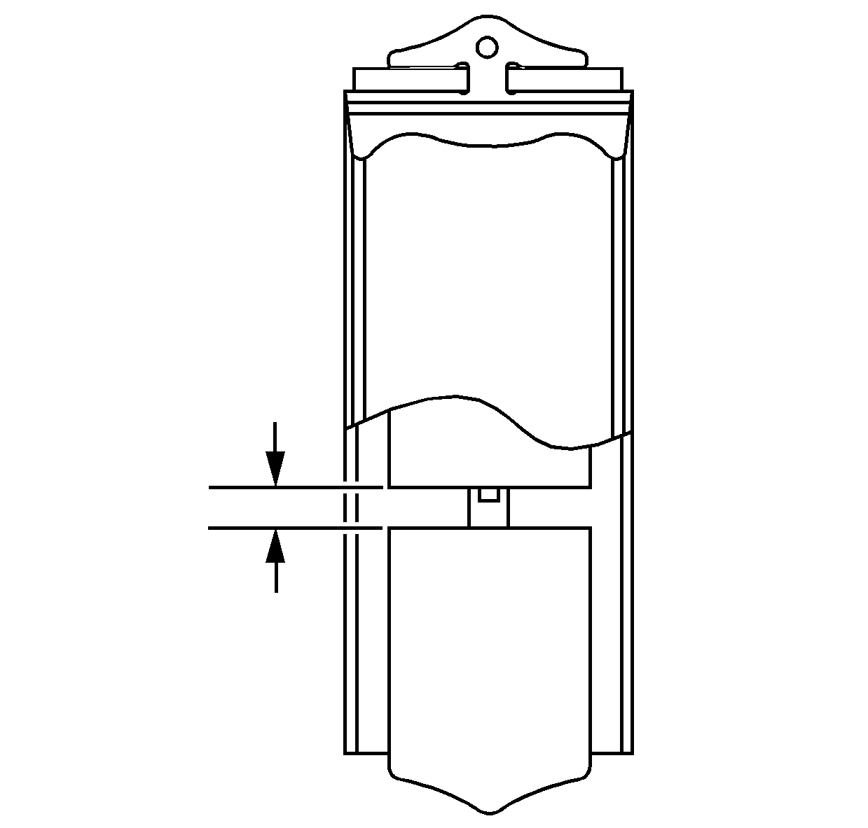
- Using a feeler gage, measure the belt end play over the full width of the belt assembly element.
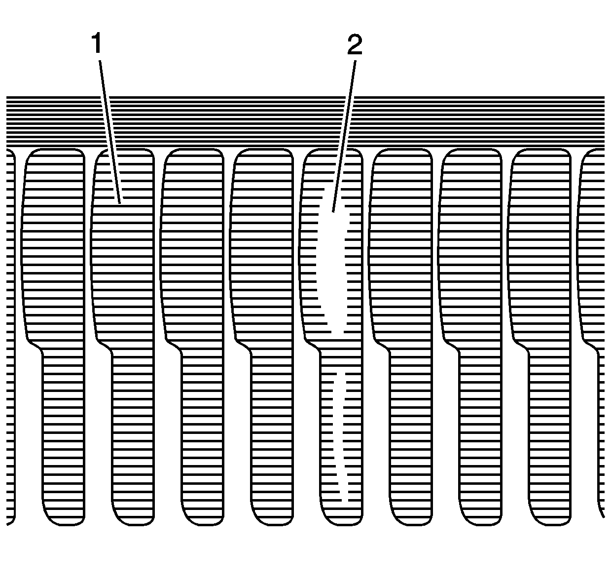
- Inspect the pulley contact area on the belt assembly elements for wear. The contact area on the elements should display visible horizontal grooves (1). These grooves can also be distinguished by feel. Worn grooves (2) indicate a slipping belt.
- Carefully install the belt assembly.
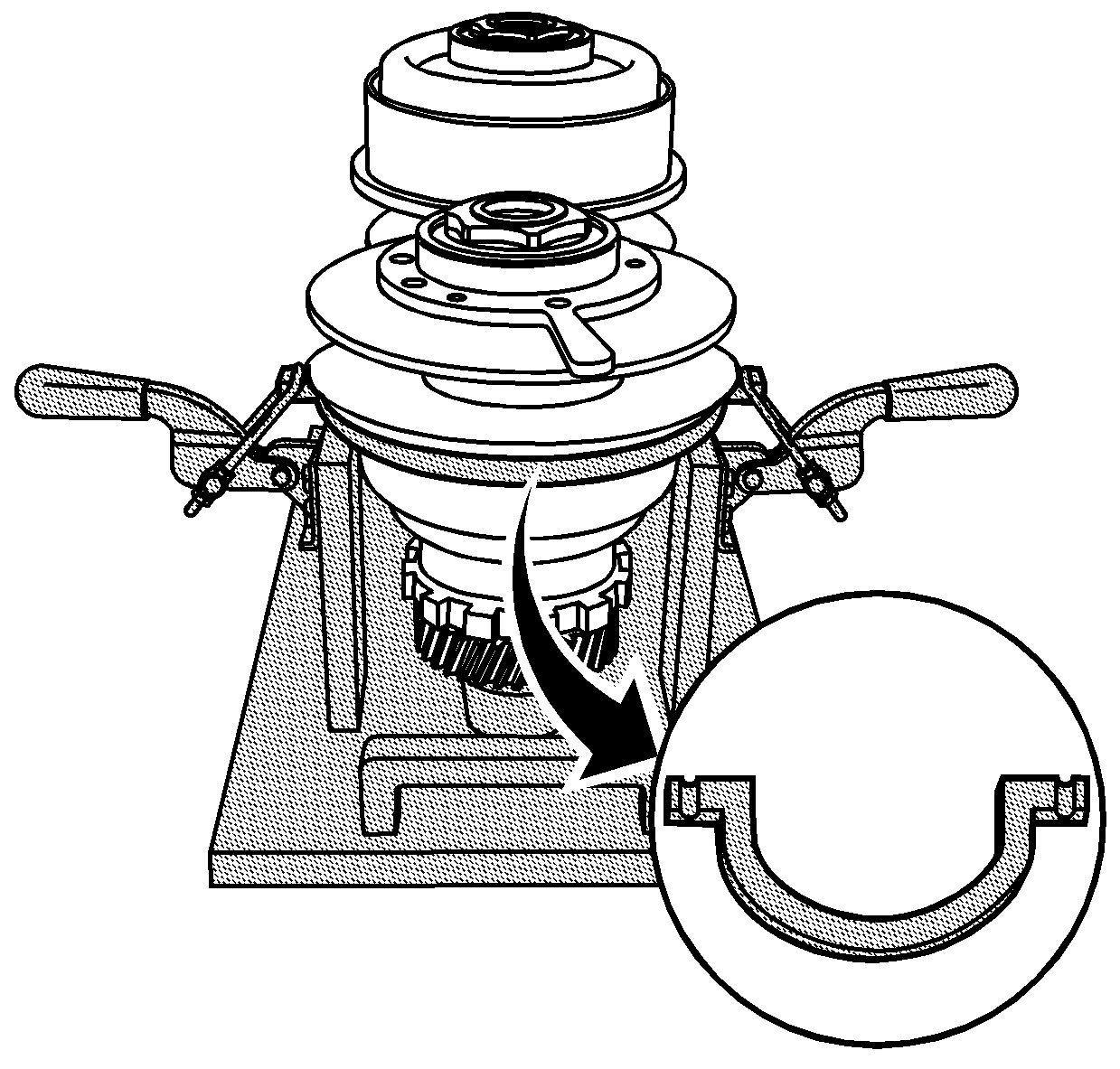
Important: When positioning the U-shaped ring of the J 44337 , ensure that the lip of the U-shaped ring is resting on the top edge of the driven pulley crimp.
Notice: Use extreme care when handling the belt assembly. Avoid metal to metal contact with the sides of the belt ringsets. Do not disassemble the belt assembly. Damage to the ringsets may cause the belt to become inoperative.
Important: Do not remove the tie straps from the belt assembly.
Important: When inspecting the belt assembly, wipe the oil from the inspection area with a soft cloth. Wear patterns are easier to distinguish when the oil is removed.
End Play Specification
The correct end play is 2.0 mm (0.079 in) or less.
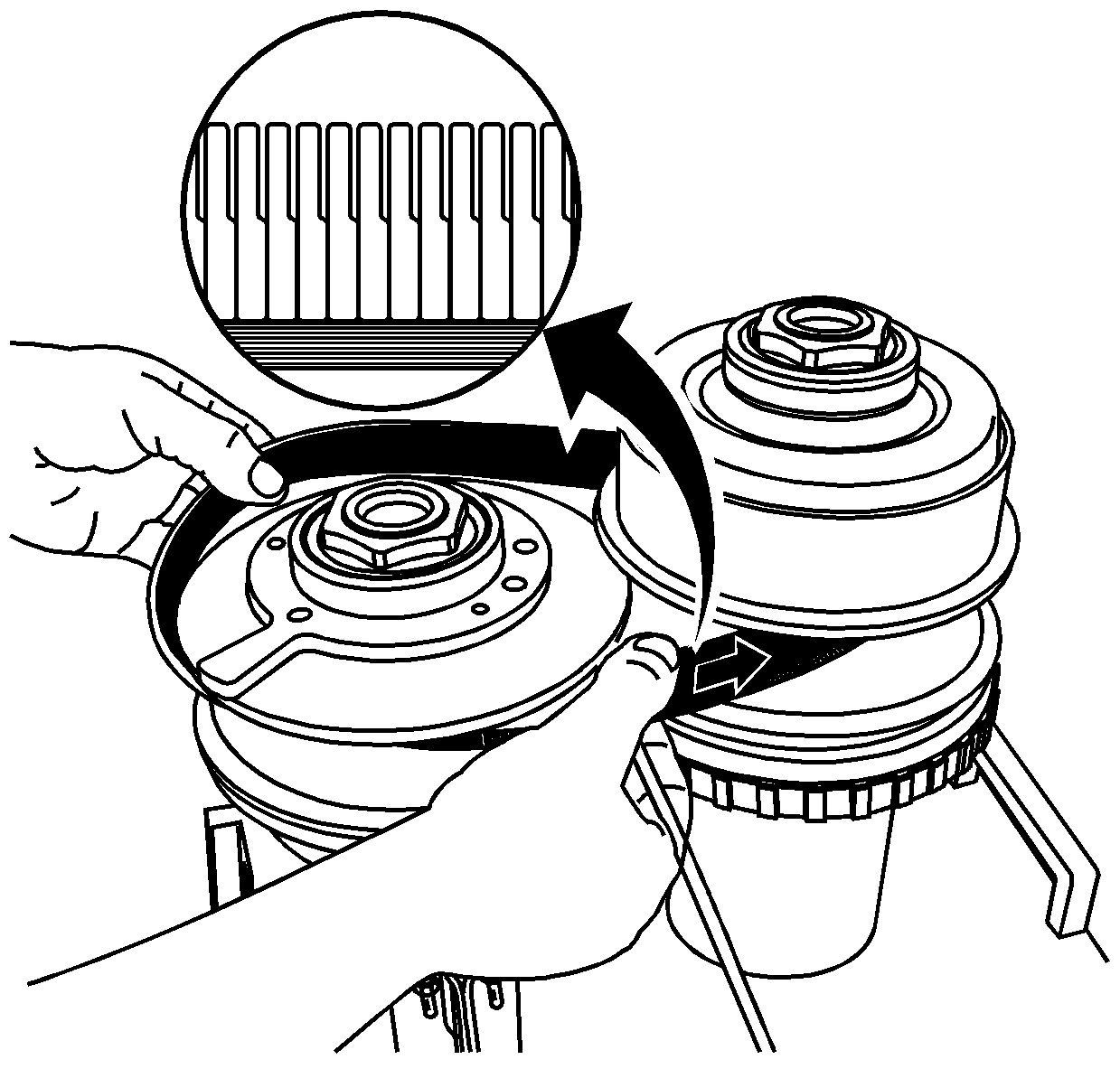
Important: When installing the belt assembly, ensure that the printed arrow on the belt assembly points to the right. If the printed arrow is not visible, install the belt assembly so that the step in the ringset element points to the right.
