- Install a NEW spacer plate assembly on the transmission case assembly.
- Install the control valve body assembly on the transmission case assembly. Ensure that the free end of the variable ratio control lever is properly positioned in the variable drive pulley follower - location 1, which is located on the case cover assembly.
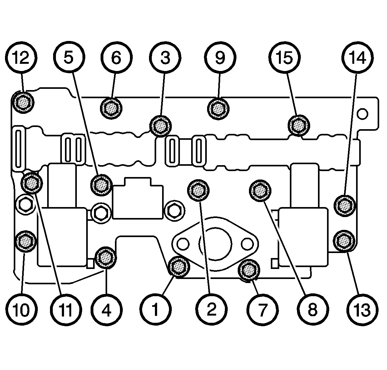
- Secure the control valve body assembly to the transmission case assembly with the 15 black bolts.
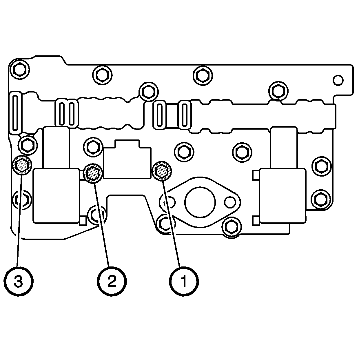
- Secure the control valve body assembly to the transmission case assembly with the 3 silver bolts.
- Connect the manual valve link assembly to the manual valve.
- Install the manual shaft detent assembly and bolt on the control valve body assembly.
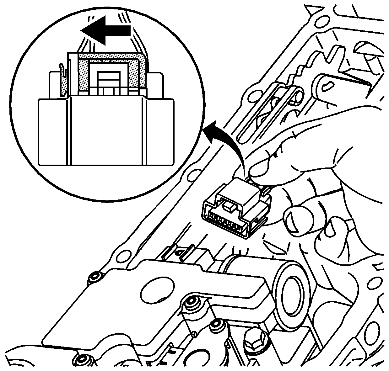
- Connect the connector for the input and output speed sensor assembly to the control valve body assembly.
- Slide the grey locking clip in order to lock the connector in place.
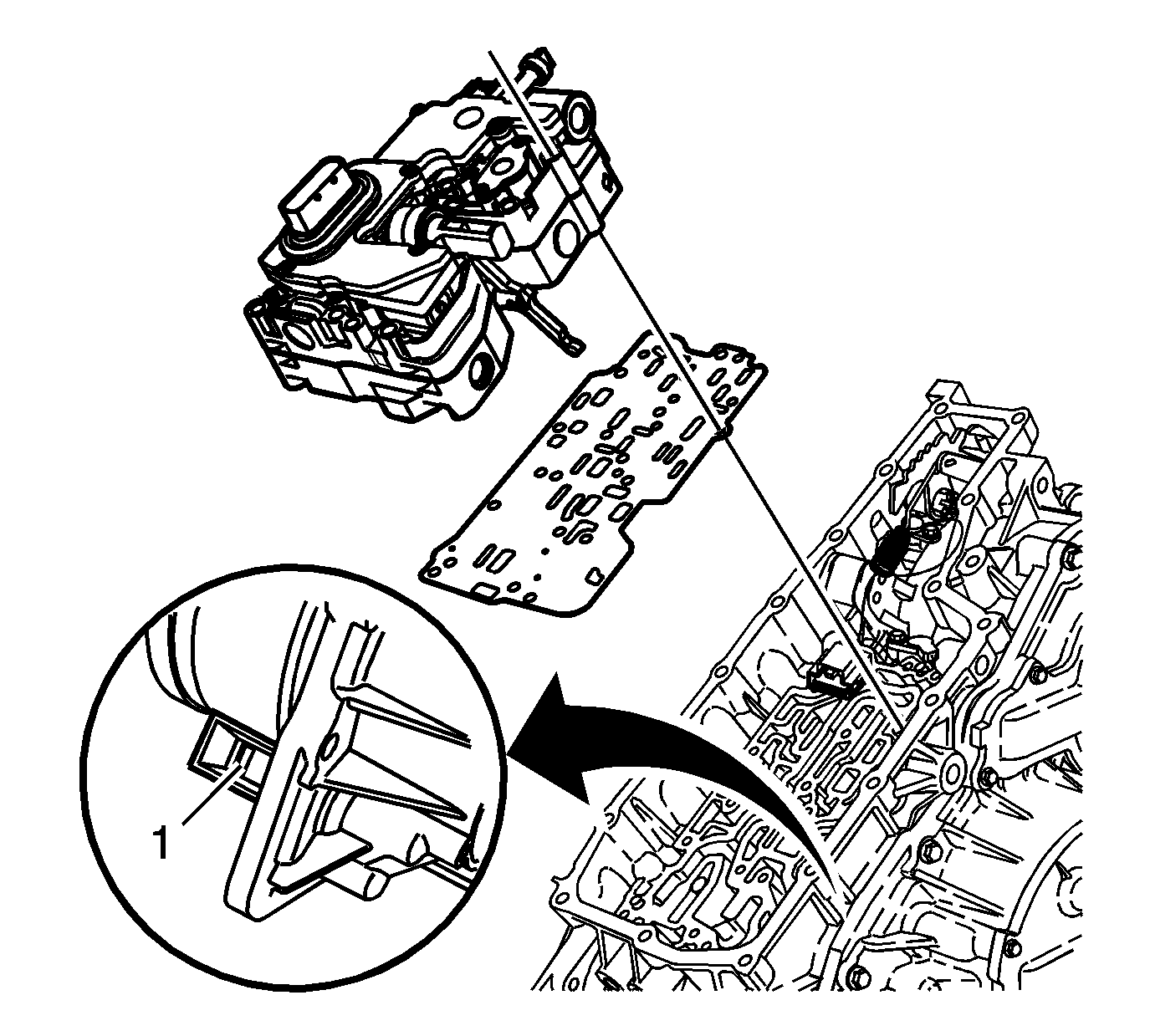
Notice: The case cover assembly must be installed before installing the control valve body assembly. Failure to follow this instruction may result in damage to the variable ratio control lever.
Tighten
Tighten the 15 black bolts in three separate
steps in the sequence shown.
| 3.1. | Tighten to 5 N·m (4 lb ft) |
| 3.2. | Tighten to 10 N·m (7 lb ft) |
| 3.3. | Tighten to 15 N·m (11 lb ft) |
Notice: Use the correct fastener in the correct location. Replacement fasteners must be the correct part number for that application. Fasteners requiring replacement or fasteners requiring the use of thread locking compound or sealant are identified in the service procedure. Do not use paints, lubricants, or corrosion inhibitors on fasteners or fastener joint surfaces unless specified. These coatings affect fastener torque and joint clamping force and may damage the fastener. Use the correct tightening sequence and specifications when installing fasteners in order to avoid damage to parts and systems.
Tighten
Tighten the 3 silver bolts to 8 N·m
(6 lb ft) in the sequence shown.
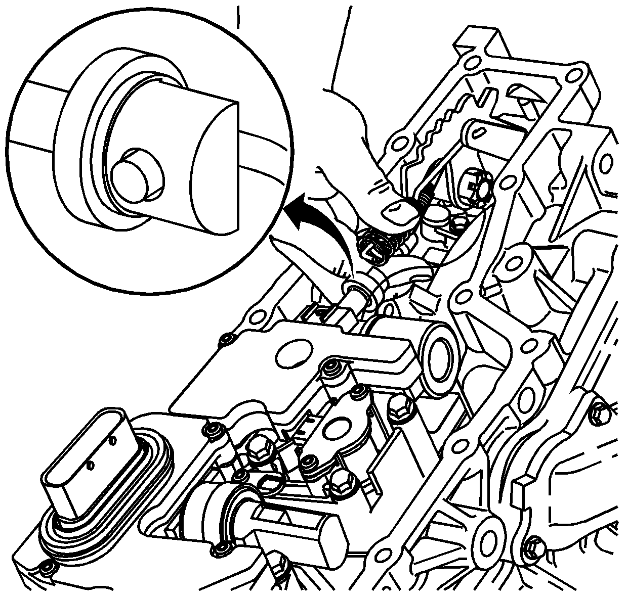
Important: Note the orientation of the manual valve before connecting the manual valve link assembly.
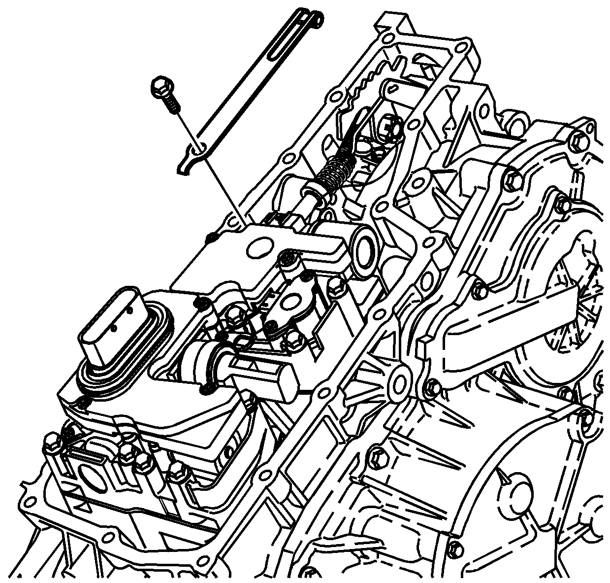
Tighten
Tighten the bolt to 11 N·m (8 lb ft).
