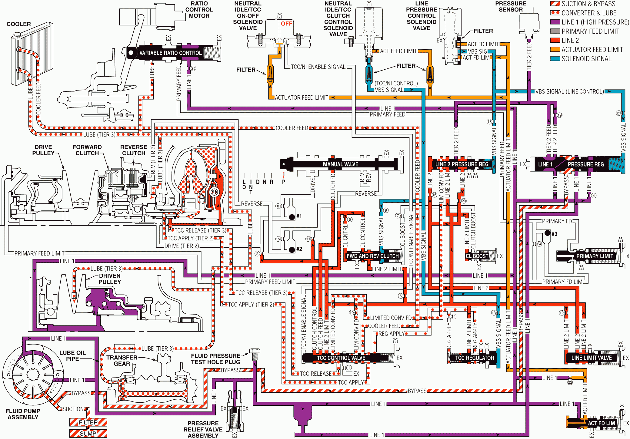
For 1990-2009 cars only
When the range selector lever is in the Park (P) position and the engine is running, fluid is drawn into the fluid pump and line 1 pressure is directed to the line 1 pressure regulator valve, the actuator feed limit valve, and the variable ratio control valve. Line 1 pressure also supplies fluid to the variable driven pulley assembly.
Pressure Regulation
Manual Valve: Mechanically controlled by the range selector lever, the manual valve is in the Park (P) position and prevents clutch feed pressure from the TCC control valve from entering the drive and reverse fluid circuits.Line Pressure Control Solenoid Valve: Actuator feed limit fluid from the actuator feed limit valve is routed to the line pressure control solenoid valve where it passes into the VBS signal (line control) fluid circuit. VBS signal fluid pressure is regulated by the line pressure control solenoid valve duty cycle and helps to regulate line 1 fluid pressure at the line 1 pressure regulator valve, and line 2 fluid pressure at the line 2 pressure regulator valve.
Line 1 Pressure Regulator Valve: VBS signal - line control fluid is routed to the line 1 pressure regulator valve and, together with spring force, opposes orificed line 1 fluid pressure to regulate line 1 fluid pressure into the tier 2 feed fluid circuit.
Line 2 Pressure Regulator Valve: VBS signal - line control fluid is also routed to the line 2 pressure regulator valve and, together with spring force, opposes orificed line 2 fluid pressure to regulate tier 2 feed fluid pressure through orifice #23 into the line 2 fluid circuit.
Actuator Feed Limit Valve: Line 1 pressure is routed through the valve and into the actuator feed limit fluid circuit. The valve limits actuator feed limit fluid pressure to a maximum pressure. Actuator feed limit fluid is routed to the line pressure control solenoid valve, the neutral idle/TCC clutch control valve, and the neutral idle/TCC On-Off solenoid valve.
Line Limit Valve: Line 2 fluid is routed to the line limit valve where it is regulated against spring force into the line 2 limit fluid circuit.
Pressure Sensor: The pressure sensor monitors tier 2 fluid pressure. The TCM uses this information to adjust the line pressure control solenoid duty cycle in order to regulate line 1 and line 2 fluid pressures.
Ratio Control
Variable Ratio Control Valve: Line 1 pressure passes through orifice #25 and is routed to the variable ratio control valve. The valve regulates line 1 pressure into the primary feed circuit in response to TCM signals to the ratio control motor.Primary Limit Valve: The primary limit valve regulates primary feed fluid pressure into the primary feed limit circuit and limits primary feed limit fluid to a maximum pressure. Primary feed limit fluid is routed to the variable drive pulley assembly.
Torque Converter
Line 2 Pressure Regulator Valve: Line 2 limit pressure is routed through the line 2 pressure regulator valve and into the limited converter feed fluid circuit. Limited converter feed fluid is routed to the TCC control valve.TCC Control Valve: Clutch control fluid passes through the valve into the clutch feed fluid circuit and is routed to the manual valve where it stops in preparation for a shift to drive or reverse.
TCC Regulator Valve: Spring force holds the valve in the released position, thereby blocking line 2 limit pressure from entering the regulated apply fluid circuit.
Neutral Idle/TCC On-Off Solenoid Valve: Controlled by the TCM, the neutral idle/TCC On-Off solenoid valve regulates filtered actuator feed limit fluid pressure into the TCC/NI enable signal fluid circuit. TCC/NI enable signal fluid is used to control the apply and release of the torque converter clutch.
Neutral Idle/TCC Clutch Control Solenoid Valve: Actuator feed limit fluid from the actuator feed limit valve is routed to the neutral idle/TCC clutch control solenoid valve where it passes into the VBS signal - TCC/NI control fluid circuit. VBS signal fluid pressure is regulated by the neutral idle/TCC clutch control solenoid valve duty cycle and is routed to the forward and reverse clutch valve and the TCC regulator valve.
Forward and Reverse Clutch Valve: VBS signal - TCC/NI control, fluid opposes forward and reverse clutch valve spring force and regulates line 2 limit fluid into the clutch control fluid circuit.
Torque Converter: TCC release fluid pressure is routed to the torque converter to keep the TCC released. Fluid leaves the converter in the TCC apply fluid circuit and returns to the cooler through the TCC control valve.
Variable Driven Pulley Assembly: Line 1 fluid is also routed to the variable driven pulley assembly in preparation for a shift to drive or reverse.
Park - Engine Running

