Front Axle Shaft Seal Replacement FWD Right
Tools Required
| • | J 43068 Axle Seal Installer |
| • | J 44015 Steering Linkage Installer |
| • | J 44017 Stub Shaft Assembly Remover |
| • | J 45000 Seal Remover |
| • | SA9133T Axle Seal Puller |
| • | SA91100C Tie Rod Separator |
| • | SA91112T Axle Seal Protector |
Removal Procedure
- Raise and support the vehicle. Refer to Lifting and Jacking the Vehicle in General Information.
- Remove the lower tube assembly and drain the fluid. Allow at least 5 minutes for the fluid to drain completely.
- Remove the drive axle assembly. Refer to Front Wheel Drive Shaft Replacement in Wheel Drive Shafts.
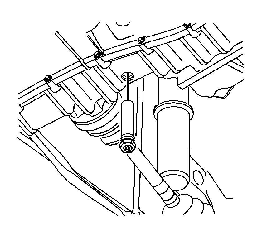
- Using the J 45000 , remove the axle seal from the torque converter and differential housing assembly. Discard the seal.
- Clean the housing seal bore.
Installation Procedure
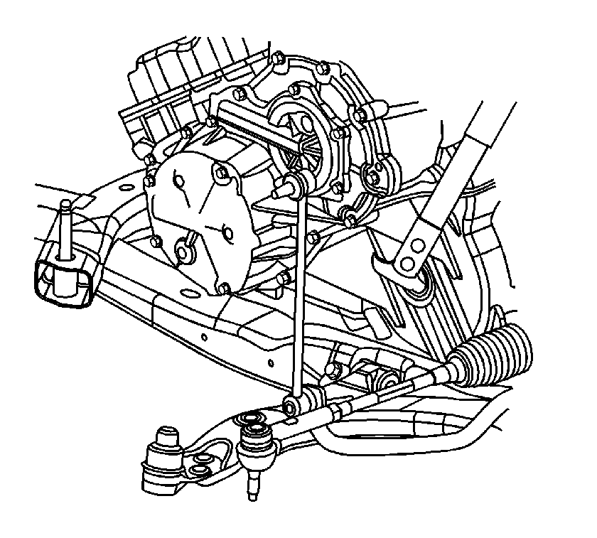
- Using the J 43068 , install the axle seal. Ensure to keep the seal lined up with the bore during installation.
- Install the drive axle assembly. Refer to Front Wheel Drive Shaft Replacement in Wheel Drive Shafts.
- Lower the vehicle.
- Using Saturn DEX-CVT® fluid P/N 22688912, fill the transmission to the proper level. Refer to Transmission Fluid Replacement .
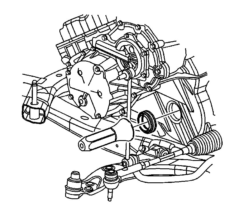
Important: Prior to installing the seal, inspect the J 43068 for nicks and burrs that may damage the seal lip.
Front Axle Shaft Seal Replacement AWD Right
Tools Required
| • | J 44015 Steering Linkage Installer |
| • | J 45341 Rear Wheel Drive Shaft Removal Tool |
| • | SA91100C Tie Rod Separator |
Removal Procedure
- Raise and support the vehicle. Refer to Lifting and Jacking the Vehicle in General Information.
- Remove the lower tube assembly and drain the fluid. Allow at least 5 minutes for the fluid to drain completely.
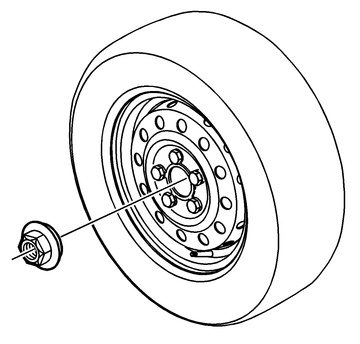
- Remove the axle shaft hub nut. Discard the nut.
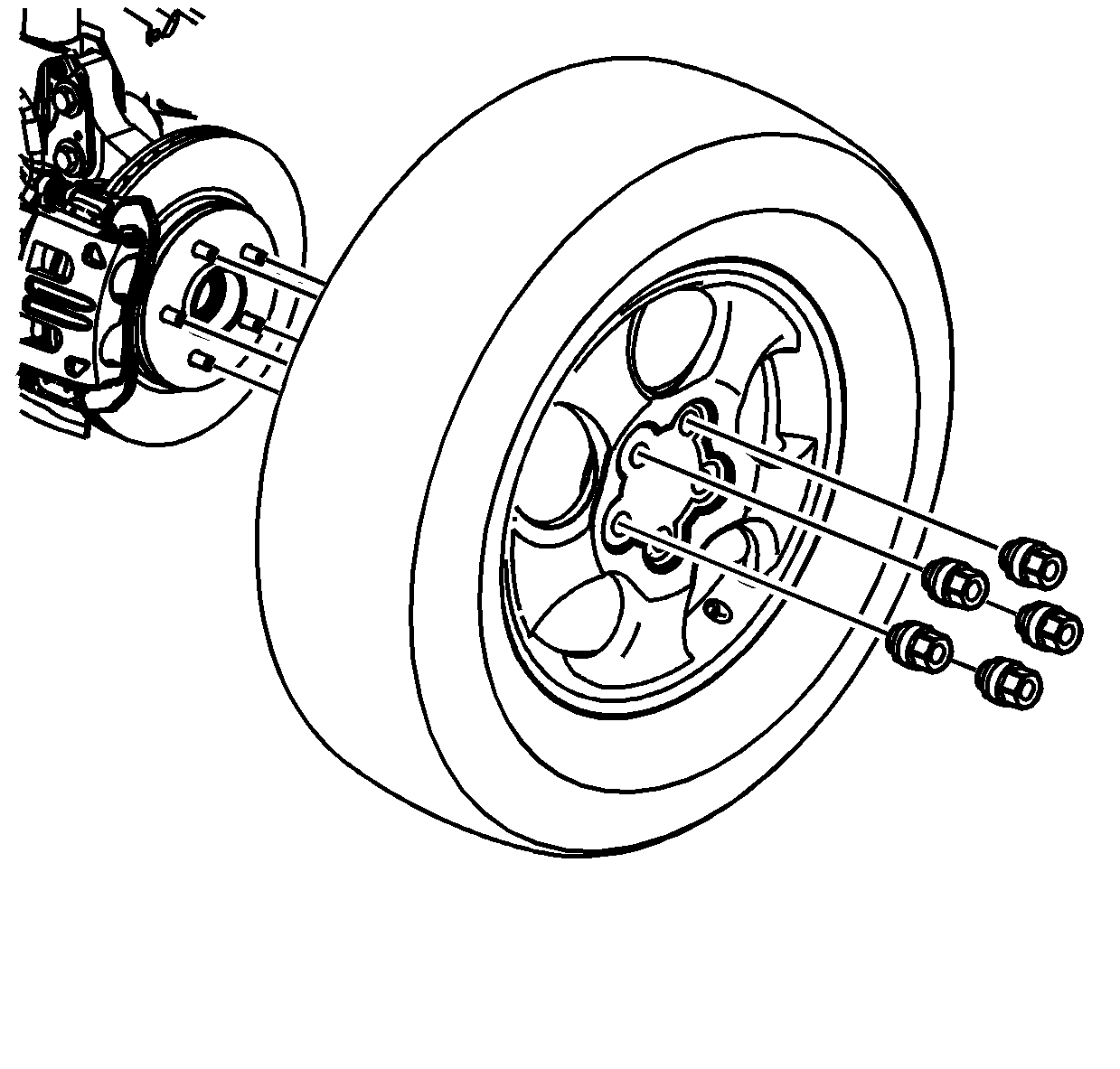
- Remove the wheel and tire from the right side of the vehicle.
- Remove the right side tie rod, outer, to knuckle nut. Discard the nut.
- Using the SA91100C or equivalent, separate the tie rod from the knuckle.
- Remove the right side lower control arm ball stud cotter pin and nut. Discard the pin.
- Disengage the ball stud from the knuckle.
- Remove the right side lower stabilizer bar link.
- Disengage the right side axle shaft from the knuckle. If the axle is difficult to remove, use a block of wood and a hammer. Do not hammer directly on the end of the axle.
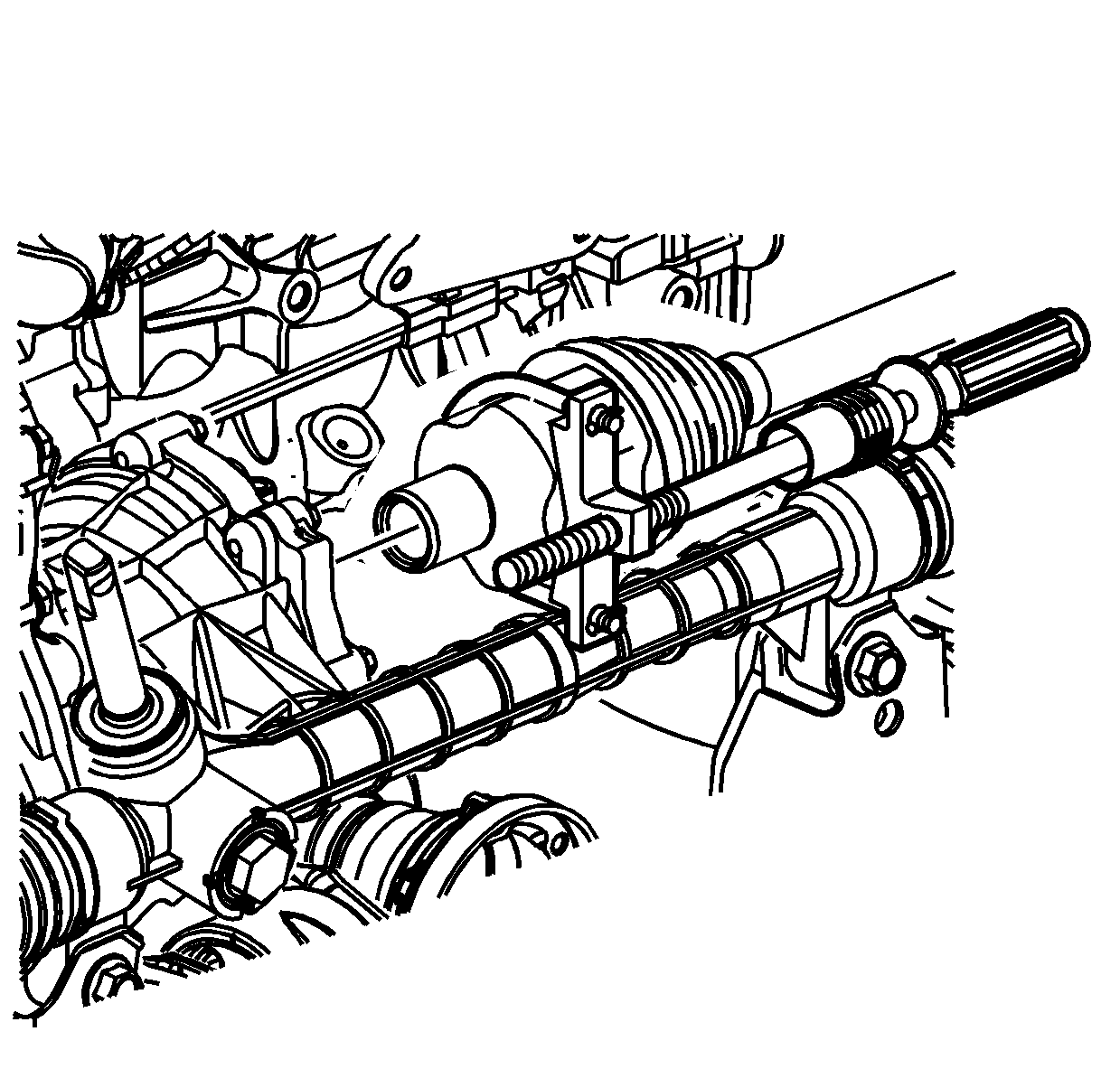
- Disengage the axle from the PTU.
- Remove the axle.
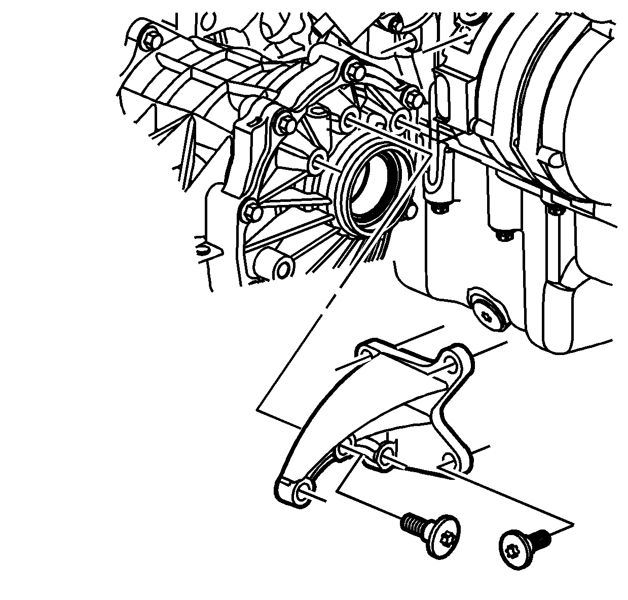
- Remove the PTU bracket that is connecting the PTU to the engine.
- Remove the PTU.
- Remove the O-ring seal from the torque converter and differential housing assembly. Discard the seal.

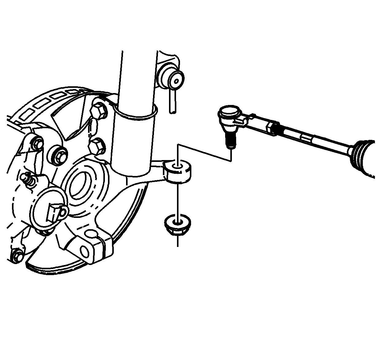
Notice: Hold the ball stud from turning when removing/installing the nut. The boot can become torn and damaged if the ball stud turns.
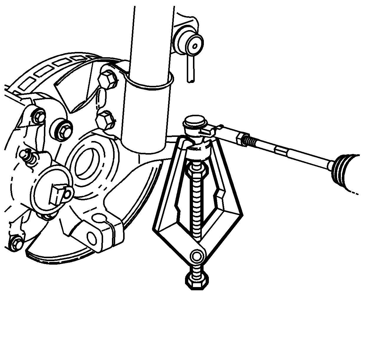
Notice: Do not attempt to separate the joint using a wedge-type tool because seal may be damaged.
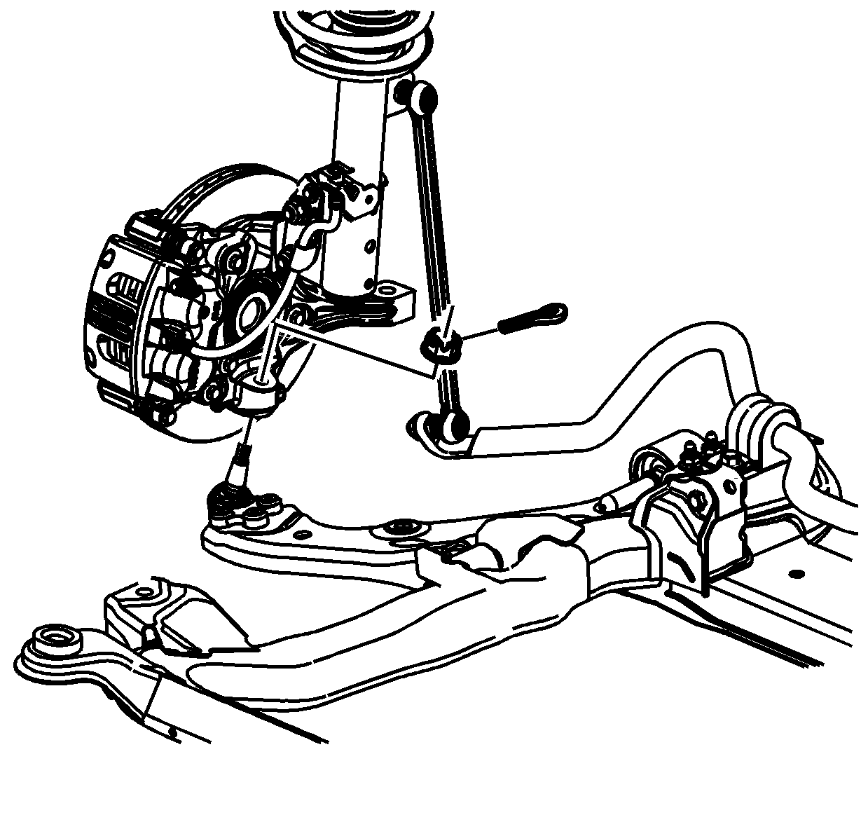
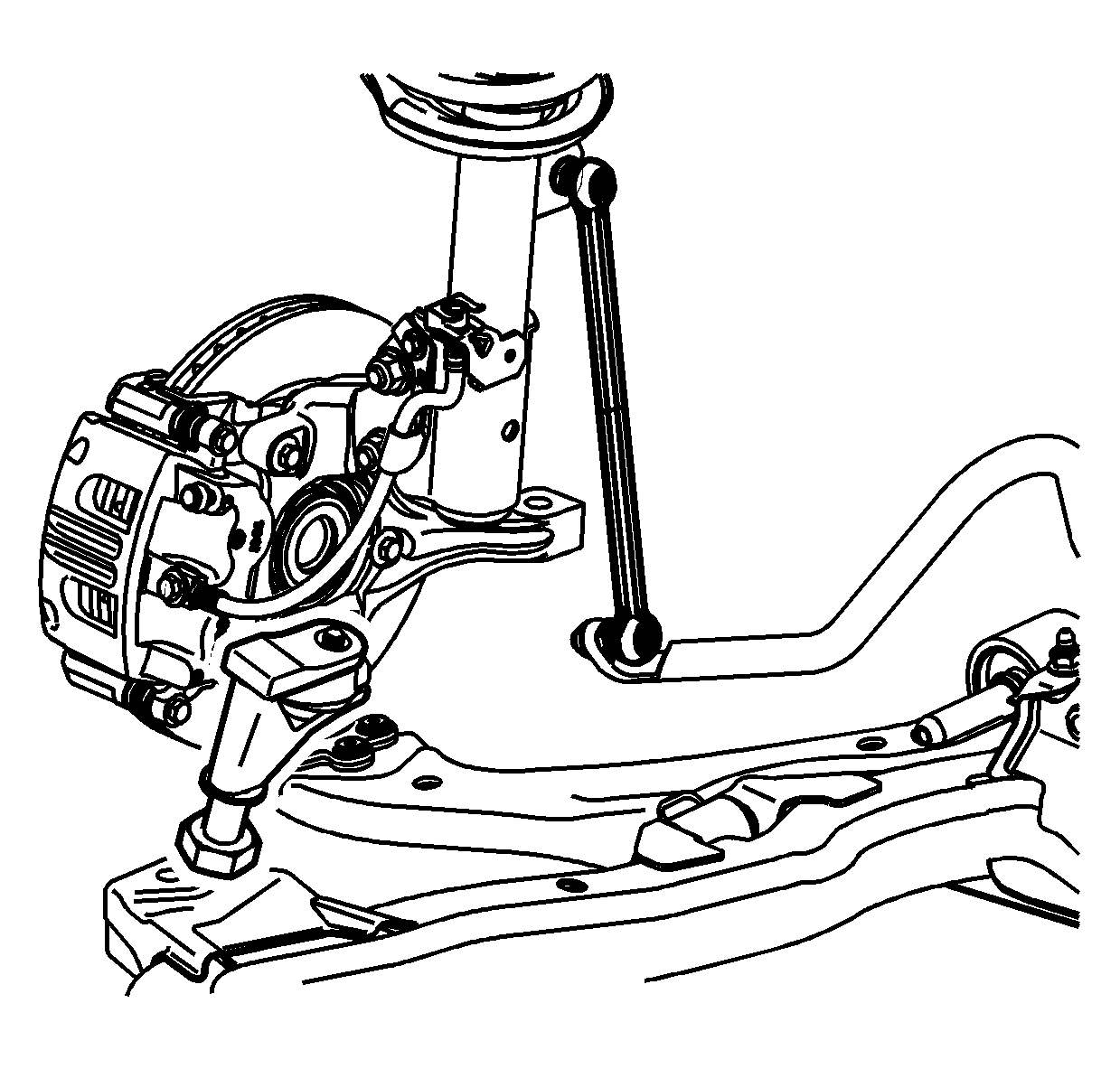
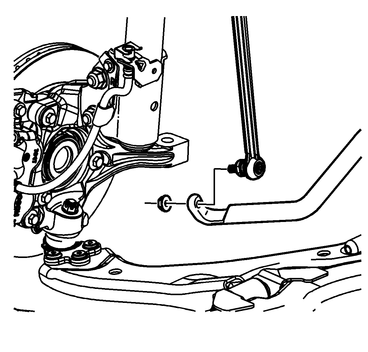
Important: Do not allow the stud to rotate. Secure the link stud with a wrench to remove the nut.
Important: The stub shaft may disengage from the power take-off unit (PTU) and separate from the axle. Plug the PTU stub shaft hole to prevent fluid loss
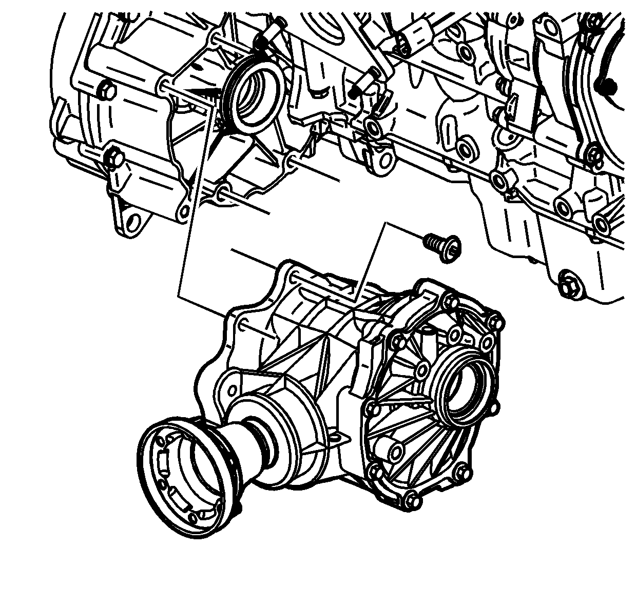
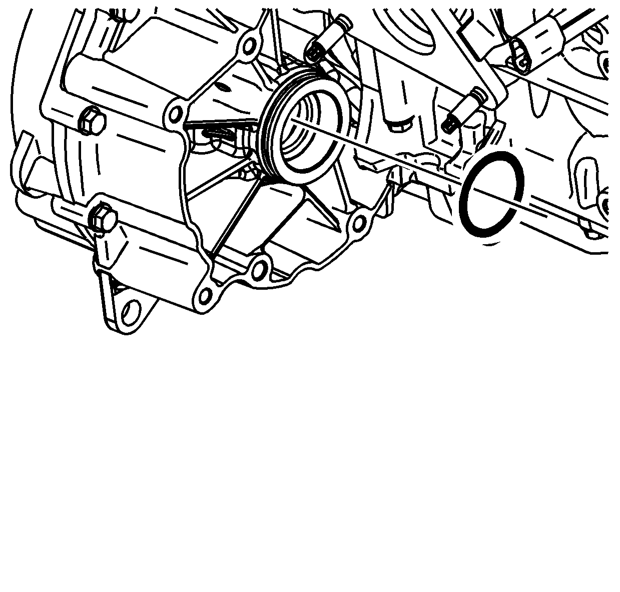
Installation Procedure
- Install a new O-ring seal on the torque converter and differential housing assembly.
- Install the PTU onto the transmission.
- Install the PTU bracket that is connecting the PTU to the engine.
- If the stub shaft is disengaged from the PTU, replace both retaining rings on the stub shaft.
- Install the stub shaft into the transmission.
- Install the drive axle to the PTU shaft. Ensure the axle is fully seated.
- Insert the outer end of the axle into the knuckle.
- Install the lower control arm ball stud to the knuckle.
- Install the nut and a new cotter pin.
- Tighten the nut one additional flat to align the cotter pin hole if necessary. Secure the cotter pin.
- Install the right side lower stabilizer bar link.
- Install a new nut.
- Insert the tie rod to the knuckle.
- Install the J 44015 and tighten.
- Remove the J 44015 .
- Install a new nut.
- Install the wheel and tire.
- Install the wheel nuts.
- Install the axle shaft hub nut.
- Lower the vehicle.
- Inspect the alignment and align as necessary. Refer to Alignment, Wheels and Tires in Wheels and Tires.
- Using Saturn DEX-CVT® fluid P/N 22688912, fill the transmission to the proper level. Refer to Transmission Fluid Replacement .


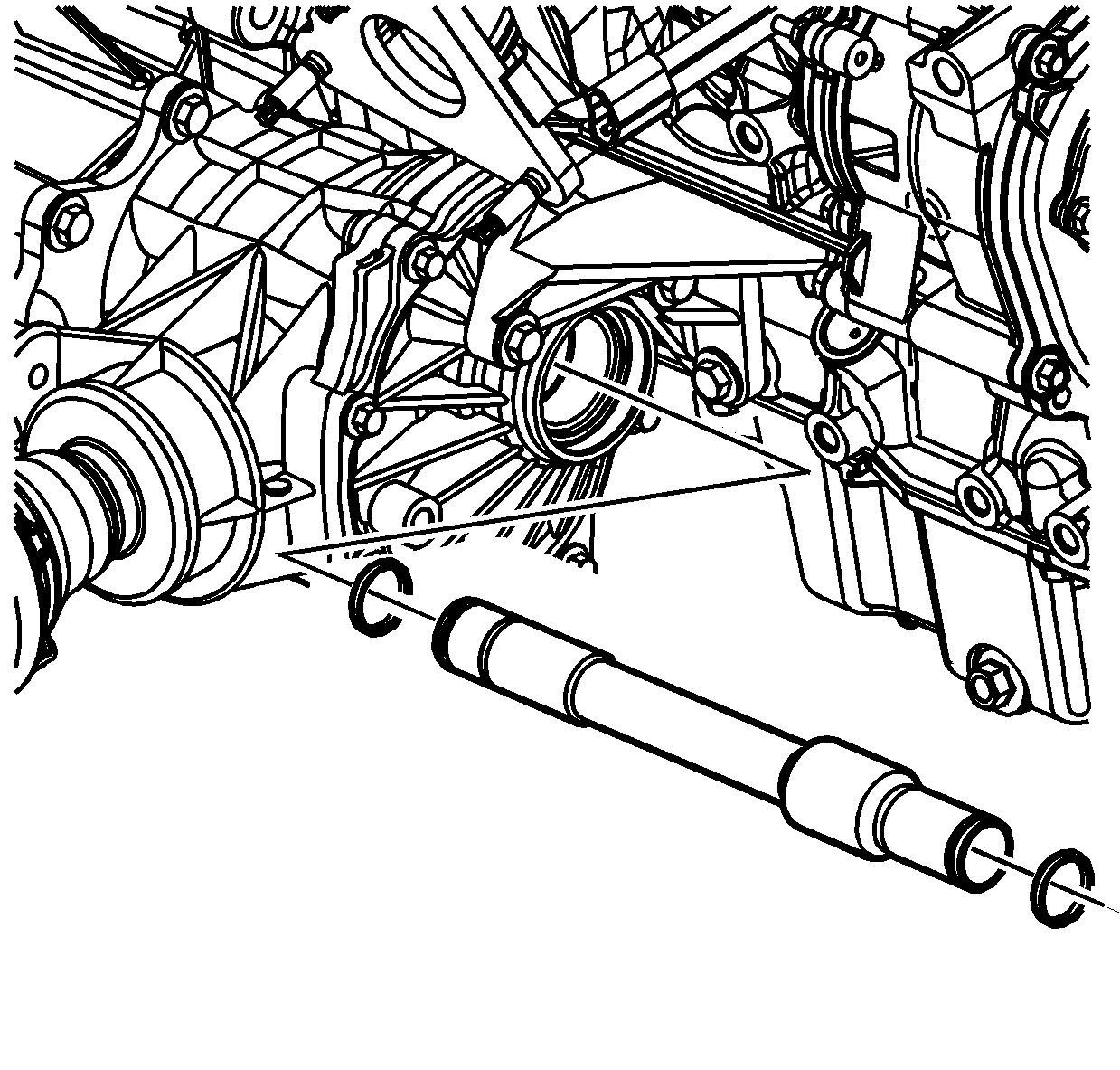
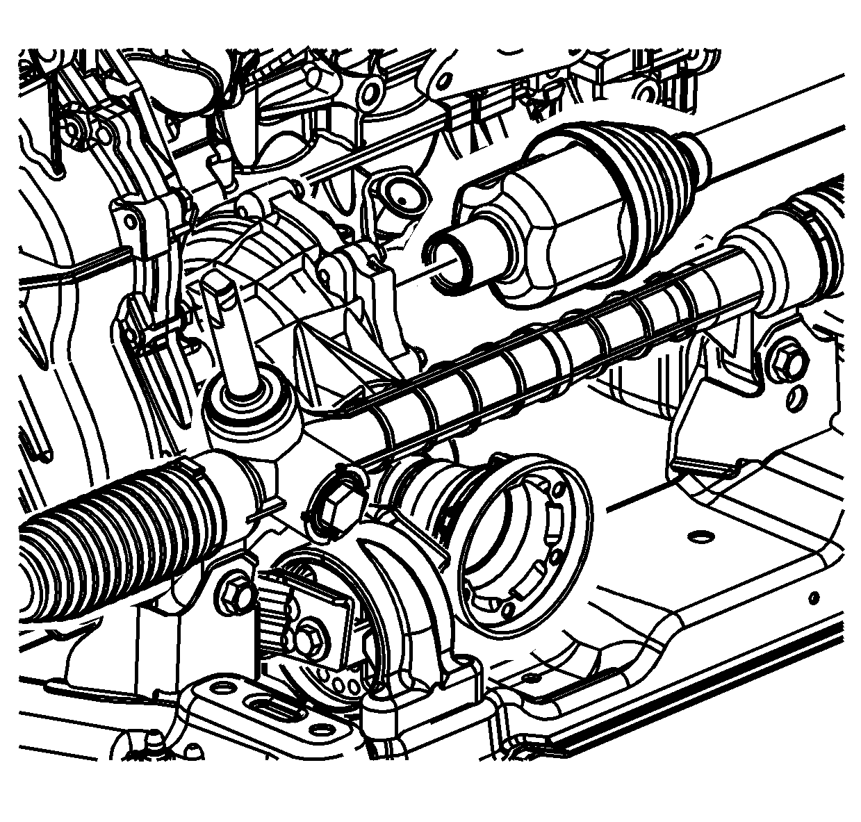
Notice: When inserting drive axle into transaxle, be careful not to contact oil seal with drive axle splines. The spline can damage the oil seal.
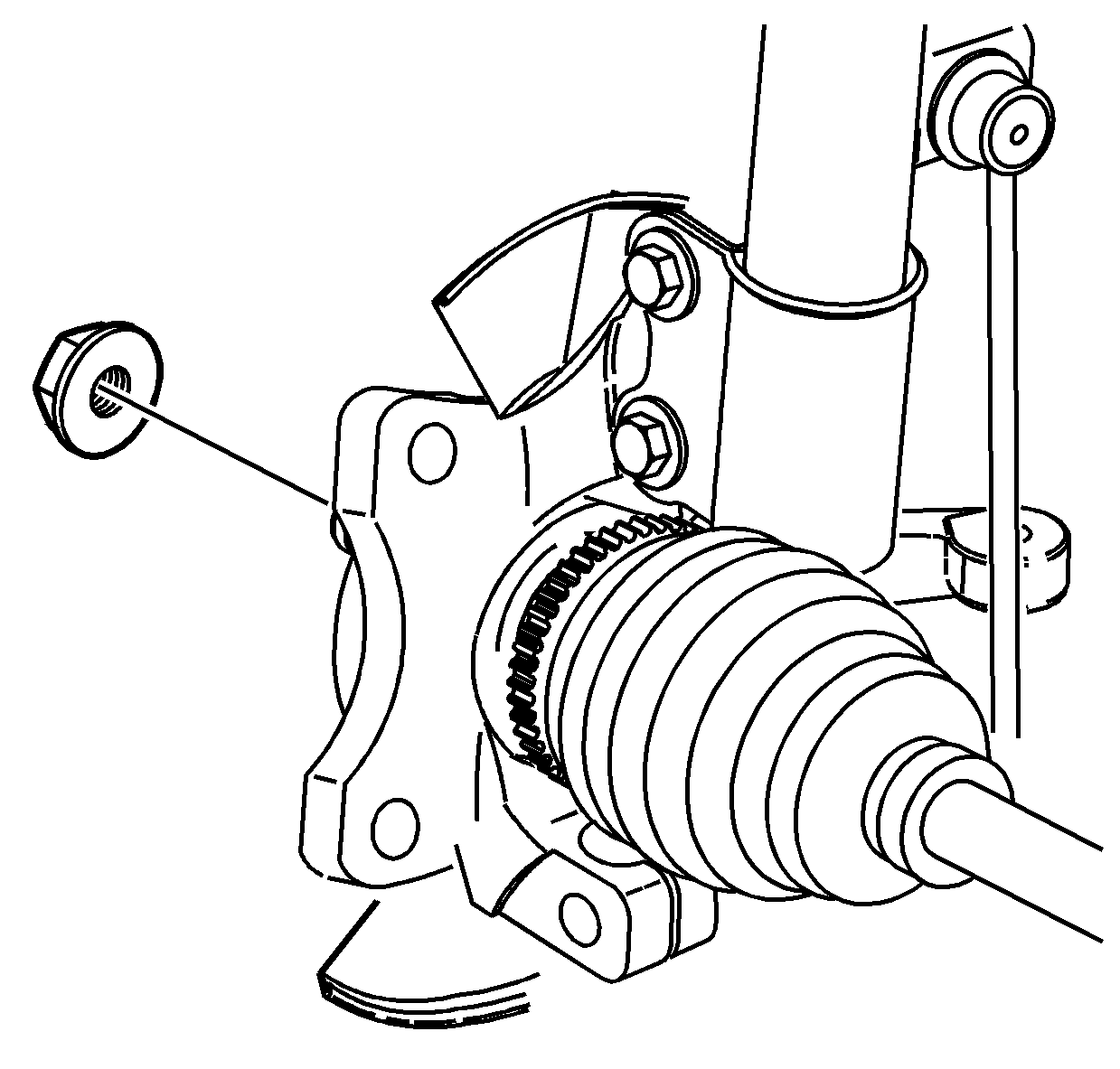
Important: Ensure not to damage the boots or seals.

Notice: Refer to Fastener Notice in the Preface section.
Tighten
Tighten the nut to 10 N·m +150 degrees (89 lb in +150 degrees).

Important: Do not allow the stud to rotate. Secure the link stud with a wrench to install the nut.
Tighten
Tighten the nut to 65 N·m (48 lb ft).
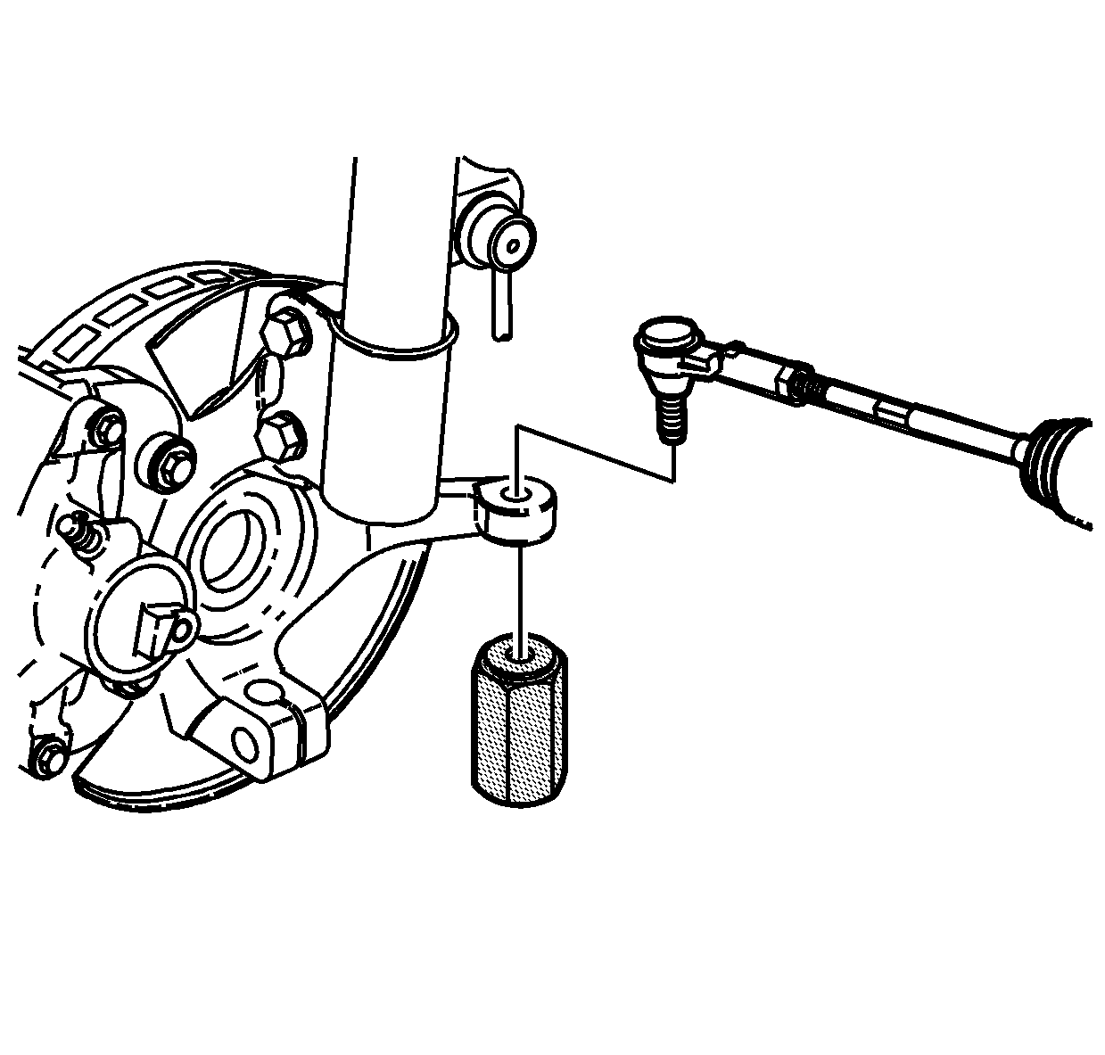
Tighten
Tighten the J 44015
to 40 N·m (30 lb ft).

Notice: Do not allow stud to rotate while tightening the nut. Damage may occur to the seal.
Tighten
Tighten the nut to 50 N·m (37 lb ft).

Tighten
Tighten the nuts in a crisscross pattern to 125 N·m (92 lb ft).

Tighten
Tighten the nut to 205 N·m (151 lb ft).
Front Axle Shaft Seal Replacement AWD and FWD Left
Tools Required
| • | J 43068 Axle Seal Installer |
| • | J 44015 Steering Linkage Installer |
| • | J 45000 Seal Remover |
| • | J 45341 Rear Wheel Drive Shaft Removal Tool |
| • | SA91100C Tie Rod Separator |
| • | SA91112T Axle Seal Protector |
| • | SA9173G Slide Hammer |
Removal Procedure
- Remove the axle shaft hub nut. Discard the nut.
- Raise and support the vehicle. Refer to Lifting and Jacking the Vehicle in General Information.
- Remove the wheel and tire from the left side of the vehicle.
- Remove the left side tie rod, outer, to knuckle nut. Discard the nut.
- Using the SA91100C or equivalent, separate the tie rod from the knuckle.
- Remove the left side lower control arm ball stud cotter pin and nut. Discard the pin.
- Disengage the ball stud from the knuckle.
- Remove the left side lower stabilizer bar link.
- Disengage the left side axle shaft from the knuckle. If the axle is difficult to remove, use a block of wood and a hammer. Do not hammer directly on the end of the axle.
- Using the J 45341 and the SA9173G , disengage the axle from the transmission. Discard the axle shaft retaining ring.
- Remove the lower tube assembly and drain the fluid.
- Remove the axle.
- Using the J 45000 , remove the axle seal from the transmission case assembly. Discard the seal.
- Clean the housing seal bore.


Notice: Hold the ball stud from turning when removing/installing the nut. The boot can become torn and damaged if the ball stud turns.

Notice: Do not attempt to separate the joint using a wedge-type tool because seal may be damaged.


Important: Do not allow the stud to rotate. Secure the link stud with a wrench to remove the nut.
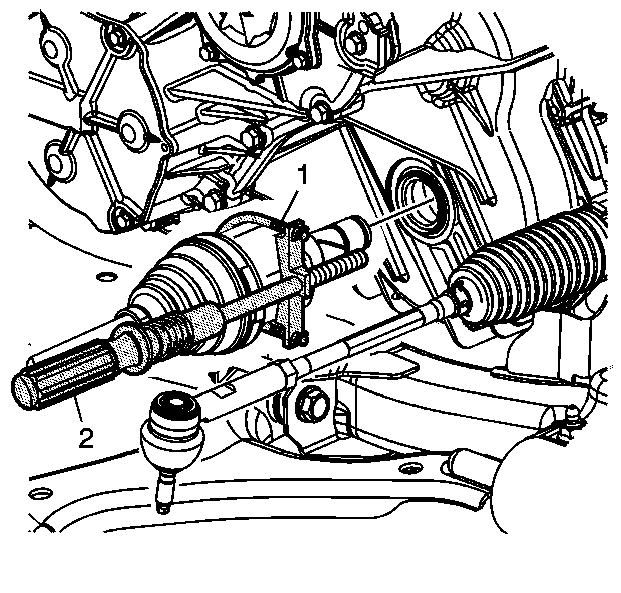

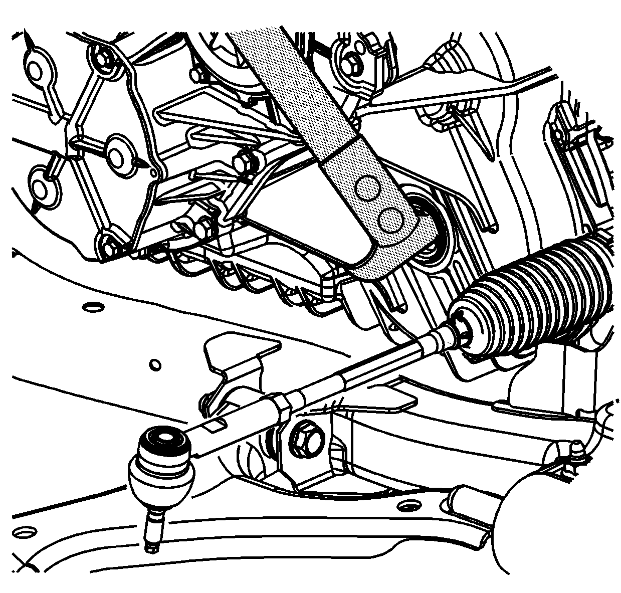
Installation Procedure
- Using the J 43068 , install the axle seal. Ensure to keep the seal lined up with the bore during installation.
- Install a new axle shaft retaining ring.
- Install the SA91112T inside the seal.
- Install the drive axle to the transmission.
- Remove the SA91112T after the axle splines pass the seal. Ensure the axle is fully seated.
- Insert the outer end of the axle into the knuckle.
- Install the lower control arm ball stud to the knuckle.
- Install the nut and a new cotter pin.
- Tighten the nut one additional flat to align the cotter pin in the hole if necessary. Secure the cotter pin.
- Install the right side lower stabilizer bar link.
- Install a new nut.
- Insert the tie rod to the knuckle.
- Install the J 44015 and tighten.
- Remove the J 44015 .
- Install a new nut.
- Install the wheel and tire.
- Install the wheel nuts.
- Install the axle shaft hub nut.
- Lower the vehicle.
- Using Saturn DEX-CVT® fluid P/N 22688912, fill the transmission to the proper level. Refer to Transmission Fluid Replacement .
- Inspect the alignment and align as necessary. Refer to Alignment, Wheels and Tires in Wheels and Tires.
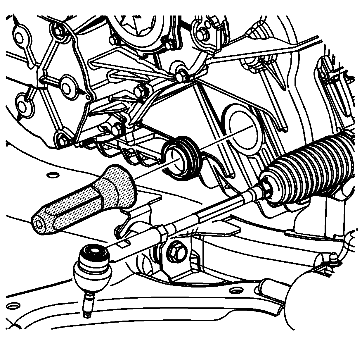
Important: Prior to installing the seal, inspect the J 43068 for nicks and burrs that may damage the seal lip.
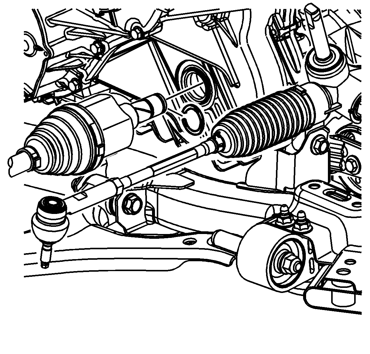
Important:
• Lubricate the axle with Saturn DEX-CVT® fluid P/N 22688912 • Do not damage the seal when inserting the axle into the transmission.
Important: Do not damage the boots or seals.


Notice: Refer to Fastener Notice in the Preface section.
Tighten
Tighten the nut to 10 N·m +150 degrees (89 lb in +150 degrees).

Important: Do not allow the stud to rotate. Secure the link stud with a wrench in order to install the nut.
Tighten
Tighten the nut to 65 N·m (48 lb ft).

Tighten
Tighten the J 44015
to 40 N·m (30 lb ft).

Notice: Do not allow stud to rotate while tightening the nut. Damage may occur to the seal.
Tighten
Tighten the nut to 50 N·m (37 lb ft).

Tighten
Tighten the nuts in a crisscross pattern to 125 N·m (92 lb ft).

Tighten
Tighten the nut to 205 N·m (151 lb ft).
