Transmission Control Module (TCM)
The transmission control module (TCM) is mounted in the engine compartment and connects directly to the wiring harness. Two 64-way connectors are used to make connections between the vehicle wiring, the transmission, and the TCM. The TCM is an electronic control module that receives input and provides output to control the operation of the VT25-E automatic transmission.
The TCM receives the following inputs from the engine control module (ECM):
| • | Engine speed and torque values |
| • | Engine intake air temperature (IAT), and throttle position (TP) information |
| • | Engine coolant temperature (ECT) |
| • | Air-conditioning (A/C) status |
| • | Cruise control status |
The engine control module (ECM) provides this data to the TCM through the GMLAN high-speed controller area network (HSCAN). A two-wire circuit is used to communicate data between the ECM and TCM, CAN H and CAN L. Other TCM inputs are the following:
| • | Battery and ignition voltage |
| • | Brake switch status |
| • | Transmission fluid temperature (TFT) |
| • | Transmission input speed sensor (ISS) |
| • | Transmission output speed sensor (OSS) |
The TCM provides the following outputs in order to control the automatic transmission:
| • | Ratio control motor to control the speed ratio of the transmission |
| • | Line pressure control solenoid (PCS) valve regulates the transmission line pressure |
| • | The TCC enable solenoid valve is used to hydraulically select whether the TCC pressure control solenoid valve will control the fluid pressure used to apply the forward and reverse clutches or the fluid pressure used to apply the torque converter clutch |
| • | TCC pressure control solenoid valve is used to control the fluid pressure used to apply and release the forward and reverse clutches, and the torque converter clutch |
Other TCM outputs provided to the ECM are the following:
| • | MIL illumination request |
| • | Vehicle speed |
| • | Transmission input speed |
| • | Transmission fluid temperature |
| • | TCC status |
| • | Torque reduction requests |
| • | Park/Neutral Position Assembly status |
| • | Transmission service status |
TCM Programming Procedures
- The transmission control module (TCM) must be programmed with the proper software/calibrations. Ensure that the following conditions exist in order to prepare for TCM programming:
- Program the TCM using the latest software matching the vehicle. Refer to up-to-date service stall equipment user instructions.
- If the TCM fails to program, proceed as follows:
| • | The battery is fully charged. |
| • | The ignition is in the RUN position. |
| • | The service stall equipment cable connection at the data link connector (DLC) is secure. |
| • | Ensure that the TCM connection is OK. |
| • | Inspect the service stall equipment for the latest software version. |
| • | Attempt to program the TCM. If the TCM still cannot be programmed properly, replace the TCM. |
Park/Neutral Position Switch Assembly
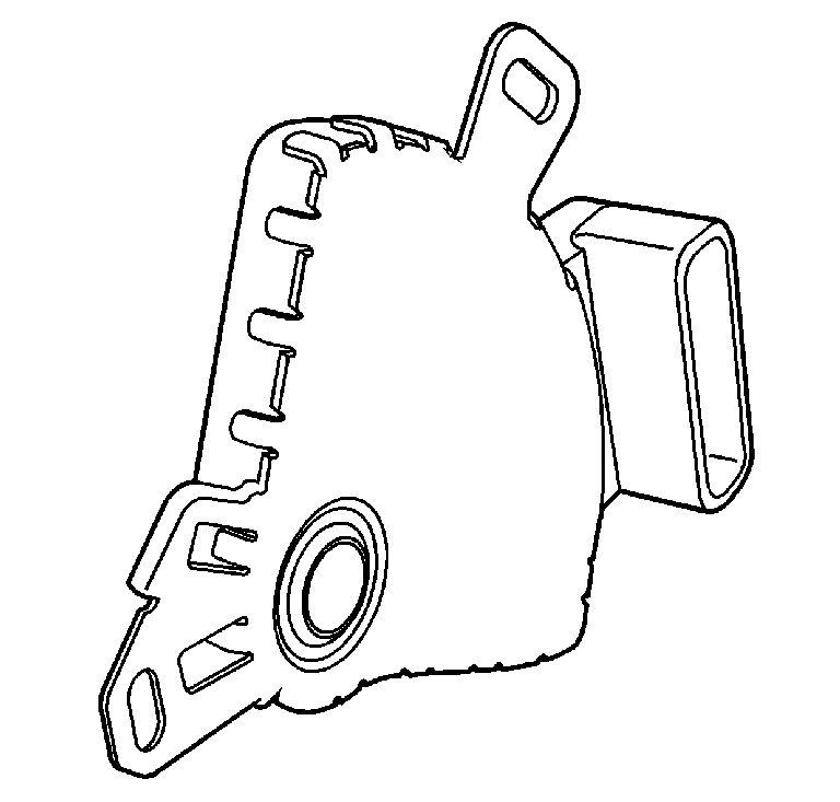
The park/neutral position switch assembly is a sliding contact switch attached to outside of the automatic transmission case assembly and splined to the manual shift shaft. The four inputs to the TCM from the park/neutral position switch assembly indicate which position is selected by the transmission selector lever. This information is used for engine controls as well as determining the transmission ratio control patterns. The state of each input is available for display on the scan tool. The four input parameters represented are Mode A, Mode B, Mode C and Mode P (P/N Start).
Module Leadframe
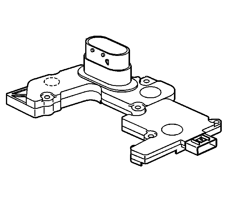
The leadframe is used to replace a conventional wiring harness and connects the various module components to the integral pass through connector. The leadframe also incorporates a 7-way speed sensor connector and a temperature sensor.
Automatic Transmission Input and Output Speed Sensor Assembly
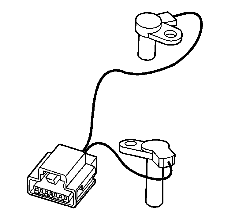
The input and output speed sensor assembly is mounted inside the transmission, under the control valve body cover. Both sensors are variable reluctance magnetic pickups and are wired into the same connector, which plugs into the control solenoid valve assembly. The sensors consist of a permanent magnet surrounded by a coil of wire.
Input Speed Sensor (ISS)
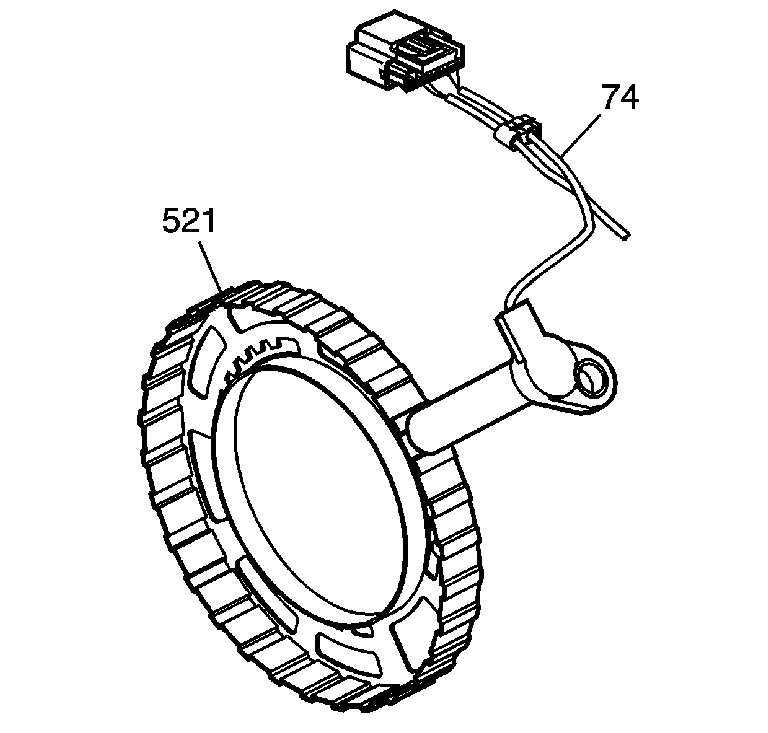
The ISS is positioned next to the input speed sensor reluctor ring assembly (521) and has an air gap of 1.143-2.77 mm (0.045-0.109 in) between the reluctor ring teeth and the magnetic pickup. As the input speed sensor reluctor ring assembly rotates, an alternating current (AC) is induced in the coil by the "teeth" on the reluctor ring as they pass by the magnetic pickup. Therefore, whenever the turbine shaft, input shaft assembly, is turning, the ISS produces an AC voltage signal proportional to turbine speed. At the TCM, the AC signal is electronically conditioned to a 5-volt square wave form. The square wave form can then be interpreted as transmission input speed by the TCM through the frequency of square waves in a given time frame. The square waves can be thought of as a representation of the reluctor ring teeth. Therefore, the more teeth, or waves, that pass by the magnetic pickup in a given time frame, the faster the turbine shaft is turning. The square wave form is compared to a fixed clock signal within the TCM to determine transmission input speed.
Output Speed Sensor (OSS)
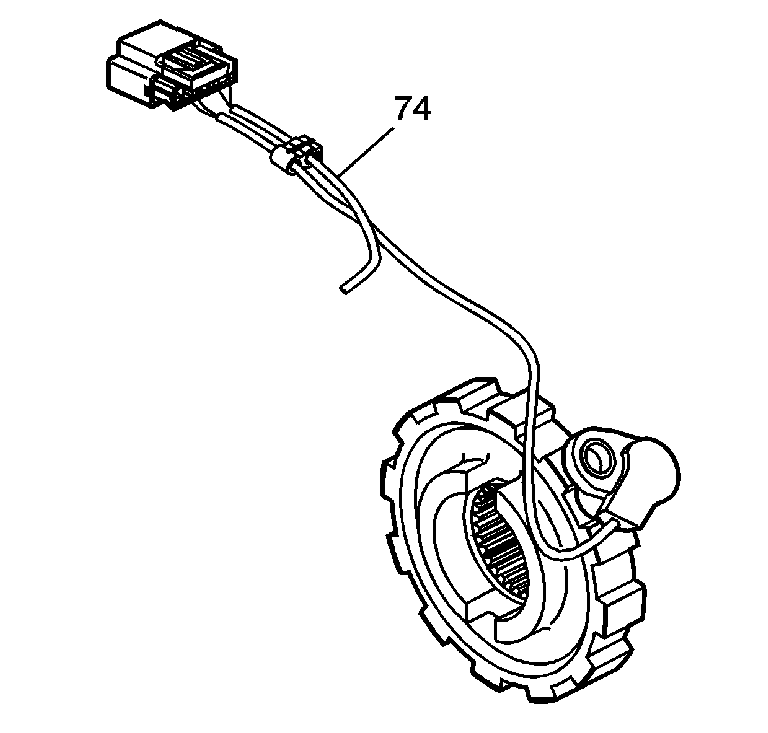
The output speed sensor (OSS) operates identically to the ISS sensor except that it uses the teeth of the parking lock gear as the rotor, reluctor. The parking lock gear is splined to the variable driven pulley assembly. The OSS has an air gap of 1.143-2.77 mm (0.045-0.109 in) between the teeth and the magnetic pickup. The OSS sensor square wave form is also compared to a fixed clock signal within the TCM to determine actual vehicle speed. The TCM uses transmission input and output speeds to help determine line pressure, transmission ratio control patterns and TCC apply pressure and timing. This speed sensor information is also used to calculate turbine speed, drive ratios, and TCC slippage for diagnostic purposes.
Transmission Fluid Pressure Sensor
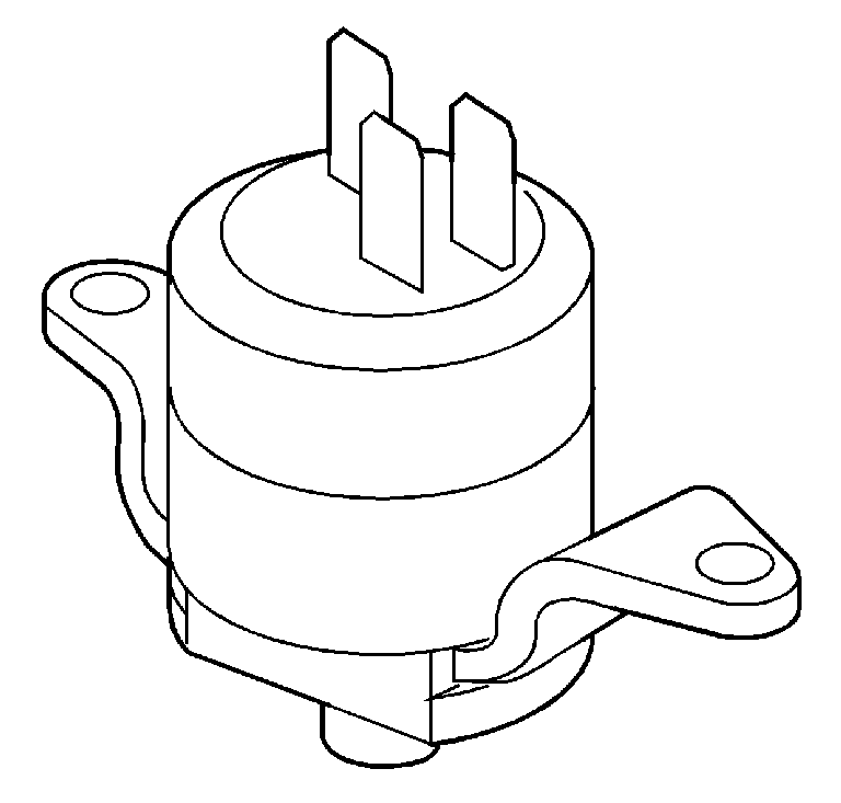
The transmission fluid pressure (TFP) sensor is used to monitor line pressure and feedback to the TCM with an analog signal of 0-5 volts. The TFP sensor is fed with tier 2 feed fluid pressure, which nominally ranges from 483-5861 kPa (70-850 psi).
Transmission Fluid Temperature -TFT - Sensor
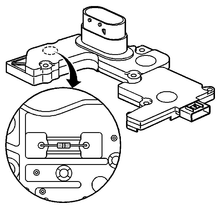
The TFT sensor is part of the module leadframe assembly, which is attached to the control solenoid valve assembly. The TFT sensor is a resistor, or thermistor, which changes value based on temperature. Refer to Transmission Fluid Temperature Sensor Specifications . The sensor has a negative-temperature coefficient. This means that as the temperature increases, the resistance decreases, and as the temperature decreases the resistance increases. The TCM supplies a 5-volt reference signal to the sensor and measures the voltage drop in the circuit. When the transmission fluid is cold, the sensor resistance is high and the TCM detects high signal voltage, counts. As the fluid temperature warms to a normal operating temperature, the resistance becomes less and the signal voltage, counts, decreases. The TCM uses this information to maintain shift quality and torque converter clutch apply quality over the operating temperature range.
If transmission fluid temperatures become excessively high, (above approximately 140°C (284°F), the TCM will disable ECCC function and command TCC lock up mode. Applying the TCC serves to reduce transmission fluid temperatures created by the fluid coupling in the torque converter with the TCC released.
Above approximately 149°C (300°F) (calibratable in the TCM), the TCM will set a transmission fluid temperature diagnostic trouble code (DTC). This causes the TCM to use a fixed value of 135°C (275°F) (calibratable in the TCM) as the transmission fluid temperature input signal.
Ratio Control Motor (RCM)
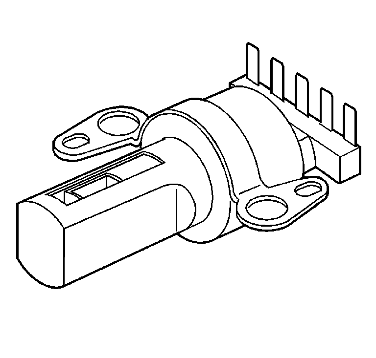
The ratio control motor - RCM is a linear position device, which changes transmission ratio by accurately controlling the position of the variable ratio control valve in order to regulate primary feed fluid flow. The RCM has a total nominal travel of 22.0 mm (0.87 in).
The transmission control module (TCM) controls the sheave ratio by adjusting the position of the RCM pintle. Movement of the pintle changes the position of the variable ratio control valve, which regulates the primary feed fluid flow and directly changes the sheave ratio. The RCM is a bi-directional motor driven by two coils. The TCM supplies a ground to apply current to the RCM in steps, counts, to extend or retract the pintle. An increase in counts will result in a larger speed ratio, smaller sheave ratio, and a decrease in counts will result in a smaller speed ratio, larger sheave ratio.
Ratio Control Motor Frequency
The RCM frequency is calculated in a 25 ms loop and used throughout the 25 ms time. The RCM counts are spaced equally for each 25 ms loop. This is accomplished by looking at how many counts are requested for this period. If all of them can be done in less than the maximum frequency, then the slower frequency is used.
Ratio Control Motor Time Delay
When there is a change in direction, the RCM must pause for a minimum time. If there is a change in frequency, then there is the same minimum pause time. The ratio control motor control algorithm incorporates a feature that will delay the count command for a calibratable amount of time when a change in direction of rotation of the ratio control motor shaft is detected. This feature is necessary because a significant amount of "lost" counts can occur due to overshoot of the rotor. The time delay allows the rotor to stabilize before beginning the rotation in the opposite direction.
Closed Loop Control
The ratio control system is a closed loop system utilizing a Proportional - Integral - Derivative (PID) controller (part of the TCM) to compensate for differences between commanded speed ratio and actual speed ratio. The PID controller utilizes the combination of proportional control action, integral control action, and derivative control action to continually adjust ratio control motor step counts in an attempt to maintain zero difference between commanded counts and actual counts. Commanded speed ratio is determined from the difference between desired speed ratio and the last commanded speed ratio. This difference is used to determine the rate at which commanded speed ratio converges to desired speed ratio. The difference between commanded speed ratio (converted to RCM counts) and actual speed ratio (converted to RCM counts) is used as the input to the PID controller which modifies the step counts of the ratio control actuator.
Open Loop Control
The closed loop ratio control algorithm will not function correctly when the transmission is in a Neutral state. This is because the variable drive pulley speed signal is not valid in Neutral and actual speed ratio becomes an invalid signal. Additionally, when a malfunction is detected in either the input or output signal, actual speed ratio will not be a valid signal. When either of these situations occur, open loop control is used to maintain actual ratio and minimize the difference between actual and commanded ratio.
Line Pressure Control Solenoid Valve
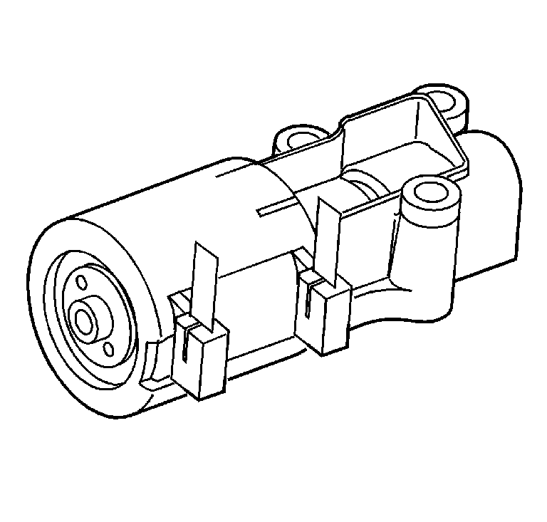
The line pressure control solenoid valve (normally-high, 3-port linear pressure control solenoid) is a precision electronic pressure regulator that controls transmission line pressure based on current flow through its coil windings. As current flow is increased, the magnetic field produced by the coil moves the solenoid's plunger further away from the exhaust port. Opening the exhaust port decreases the output fluid pressure regulated by the line pressure control solenoid valve, which ultimately decreases line pressure. The TCM controls the line pressure control solenoid valve based on various inputs including throttle position, transmission fluid temperature and ratio.
A "duty cycle" may be defined as the percentage of time current is flowing through a solenoid coil during each cycle. The number of cycles that occur within a specified amount of time, usually measured in seconds, is called "frequency". Typically, the operation of an electronically-controlled pulse width modulated solenoid is explained in terms of duty cycle and frequency.
The TCM controls the line pressure control solenoid valve on a positive duty cycle at a fixed frequency of 292.5 Hz, cycles per second. A higher duty cycle provides a greater current flow through the solenoid. The high, positive, side of the line pressure control solenoid valve electrical circuit at the TCM controls the line pressure control solenoid valve operation. The TCM provides a ground path for the circuit, monitors average current and continuously varies the line pressure control solenoid valve duty cycle to maintain the correct average current flowing through the line pressure control solenoid valve.
The duty cycle and current flow to the line pressure control solenoid valve are mainly affected by throttle position (engine torque), and they are inversely proportional to throttle angle (engine torque). In other words, as the throttle angle (engine torque) increases, the duty cycle is decreased by the TCM which decreases current flow to the line pressure control solenoid valve. Current flow to the line pressure control solenoid valve creates a magnetic field that moves the solenoid armature against spring force.
TCC Pressure Control Solenoid Valve
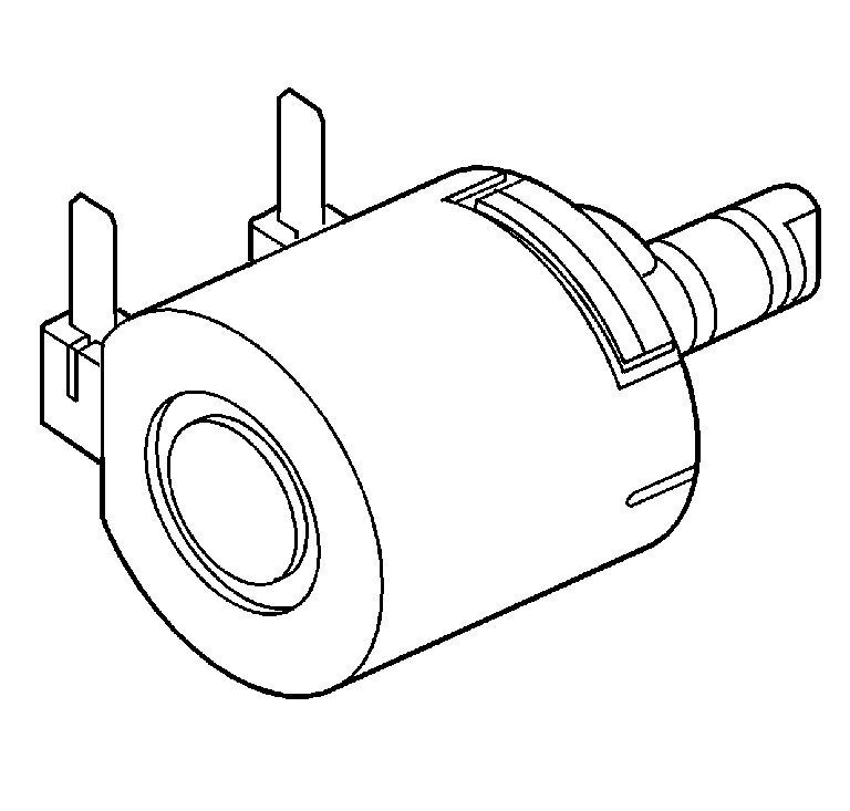
The TCC pressure control solenoid valve is a normally-low, 3-port linear pressure control solenoid that controls the fluid pressure used to apply and release the forward and reverse clutches, and the torque converter clutch. The TCM operates the solenoid with a negative duty cycle at a fixed frequency of 32 Hz to control the rate of clutch apply/release. The solenoid's ability to "ramp" the clutch apply and release pressures results in a smoother clutch operation.
TCC Pressure Control Solenoid Valve Operation
The TCC pressure control solenoid valve is one electronic control component of the TCC control system. The other electronic component is the TCC enable solenoid valve, which enables the TCC to turn ON and OFF. The other components are all hydraulic control or regulating valves.
Forward and Reverse Clutch Control
When the TCC enable solenoid valve is OFF, the TCC pressure control solenoid valve controls the fluid pressure used to apply the forward and reverse clutches.
Neutral Idle Control
The TCC pressure control solenoid valve is also used to turn OFF clutch control fluid when the TCM commands Neutral Idle. If the TCC is applied, the TCM will first turn OFF the TCC enable solenoid valve to release the torque converter clutch. The TCM then ramps the TCC pressure control solenoid valve duty cycle up to approximately 98 percent to move the forward and reverse clutch valve against spring force, block line 2 limit fluid, and open the clutch control circuit to exhaust. This causes the forward or reverse clutch to release and places the transmission in a Neutral condition.
Torque Converter Clutch Control
When the TCC enable solenoid valve is ON, the TCC pressure control solenoid valve controls the fluid pressure used to apply the torque converter clutch. In drive range, at approximately 13 km/h (8 mph), the TCM operates the TCC pressure control solenoid valve at approximately 90 percent duty cycle. This duty cycle is maintained until a TCC apply is commanded. When vehicle operating conditions are appropriate to apply the TCC, the TCM immediately decreases the duty cycle to 0 percent, then increases it to approximately 25 percent. The TCM then ramps the duty cycle up to approximately 50 percent to achieve regulated apply pressure in vehicles equipped with the Electronically Controlled Clutch Capacity (ECCC) system. With the ECCC system, the pressure plate does not fully lock to the torque converter. Instead, a consistent slip of 20-40 RPM is regulated. The rate at which the TCM increases the duty cycle controls the TCC apply. Similarly, the TCM also ramps down the TCC pressure control solenoid duty cycle to control TCC release. Under some high torque or high vehicle speeds, the converter clutch is fully locked. There are some operating conditions that prevent or enable TCC apply under various conditions. Refer to Transmission Fluid Temperature Sensor Specifications . Also, if the TCM receives a high voltage signal from the brake switch, signalling that the brake pedal is applied, the TCM immediately releases the TCC.
TCC Enable Solenoid Valve
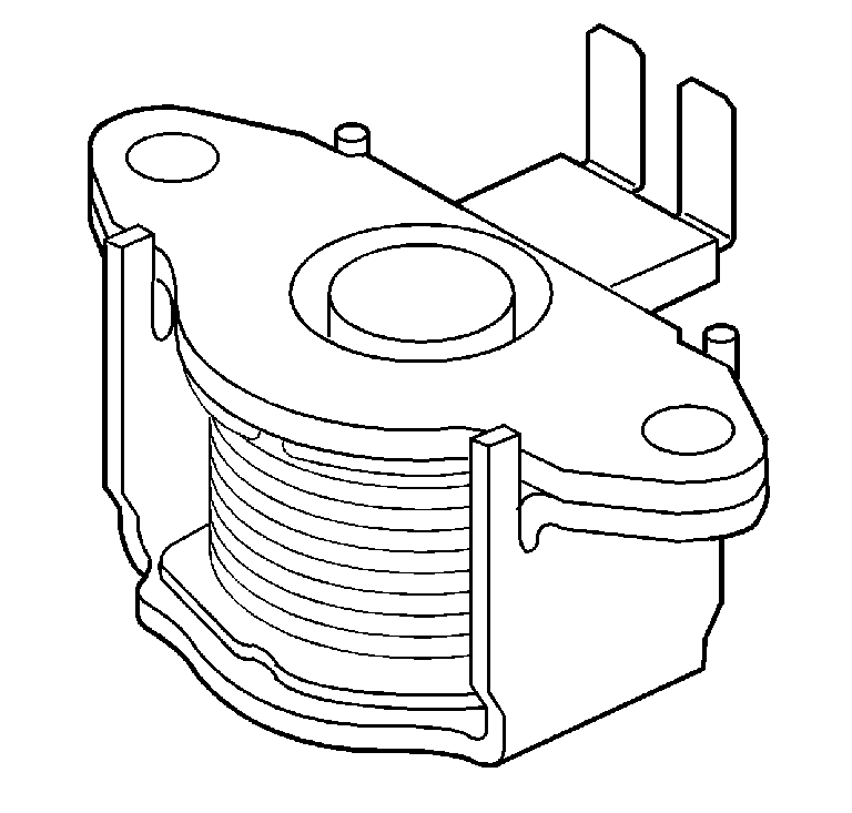
The TCC enable solenoid valve is a normally-closed, 3-port, ON/OFF solenoid controlled by the TCM. It is used to hydraulically select which fluid pressure, clutch control or regulated apply, will be controlled by the TCC pressure control solenoid valve. When the TCC enable solenoid valve is de-energized, actuator feed limit fluid pressure is blocked from pressurizing the TCC/NI enable signal fluid circuit. Without TCC/NI enable signal fluid pressure at the end of the TCC control valve, spring force holds the valve in the released position.
When vehicle operating conditions are appropriate for TCC apply, the TCM provides a ground for the TCC enable solenoid valve electrical circuit. Electrical current flows through the coil assembly in the solenoid and creates a magnetic field. The magnetic field moves the plunger and valve to allow actuator feed limit fluid to pass through the solenoid into the TCC/NI enable signal circuit. TCC/NI enable signal fluid pressure increases at the TCC control valve and moves the valve against spring force to the apply position.
Under normal operating conditions, the torque converter clutch only applies when the transmission is in an Overdrive ratio, in DRIVE range. However, at high speeds under heavy throttle conditions, the TCM will command TCC apply when in Intermediate range. Also, when transmission fluid temperature is above approximately 135°C (275°F), the TCC is applied all of the time in DRIVE range to help reduce transmission fluid temperatures.
When the TCM commands TCC release, the ground for the TCC enable solenoid valve electrical circuit is opened, causing the solenoid to block actuator feed limit fluid and open the TCC/NI enable signal circuit to an exhaust. TCC/NI enable signal fluid pressure exhausts from the TCC control valve and spring force moves the valve to the released position.
Other conditions that cause the TCM to change the operating state of the TCC enable solenoid valve include:
| • | The TCC is released when the vehicle decelerates and the TCM commands Neutral Idle. |
| • | The TCC is released when the brake pedal is applied. |
| • | The TCC is released under minimum and maximum throttle conditions. |
| • | TCC apply is prevented until engine coolant temperature is above approximately 20°C (68°F). |
| • | TCC apply is prevented until transmission fluid temperature is above approximately 29°C (84°F). |
