Removal Procedure
- Disable the frontal SIR system. Refer to SIR Disabling and Enabling in SIR.
- Remove the windshield garnish moldings. Refer to Windshield Upper Garnish Molding Replacement .
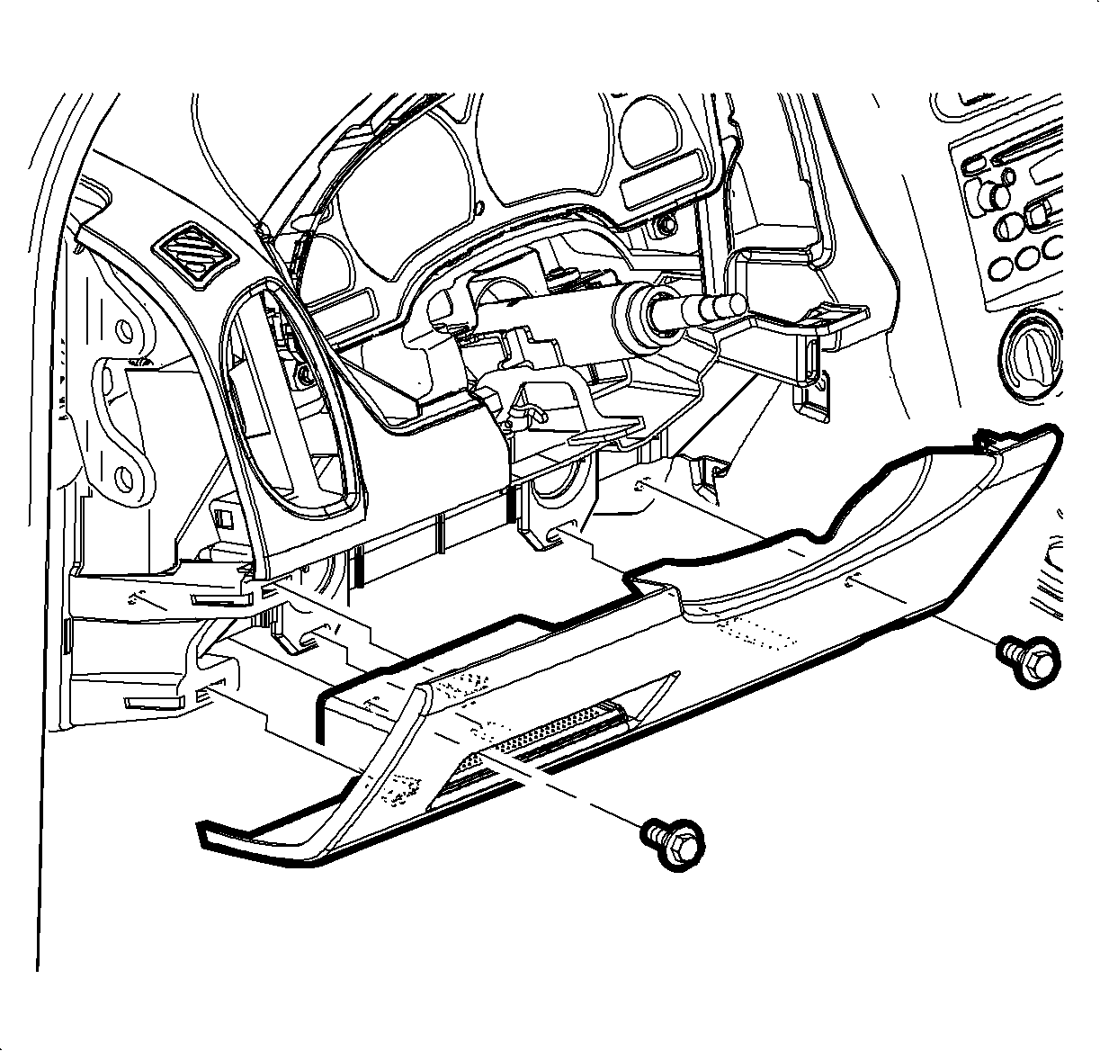
- Remove the screws from the steering column filler panel.
- Pull to remove the filler panel.
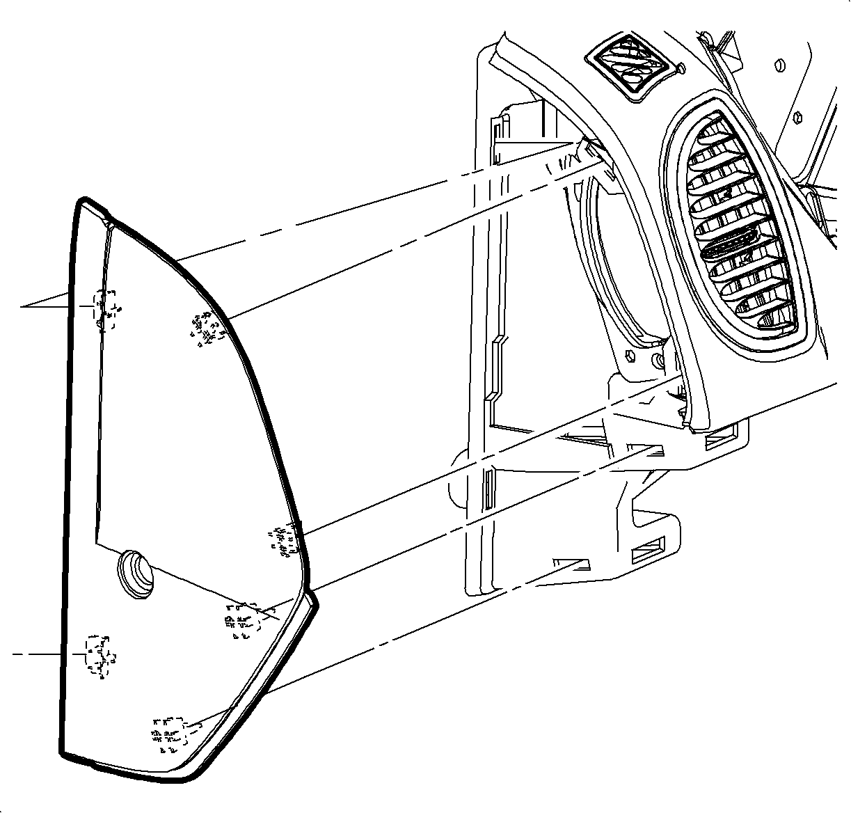
- Pull to remove the left I/P outer trim cover.
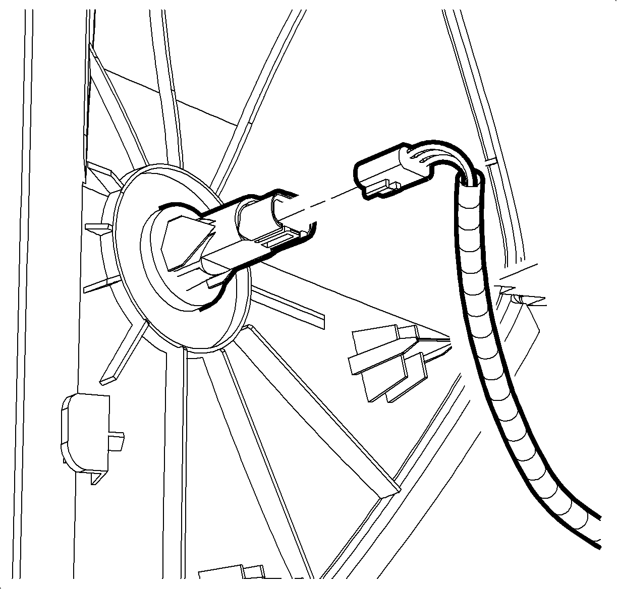
- Disconnect the doorjamb switch electrical connector.
- Remove the right I/P outer trim cover.
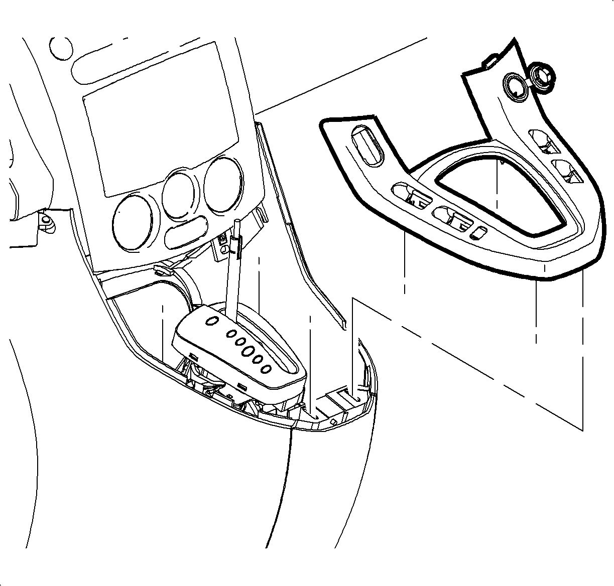
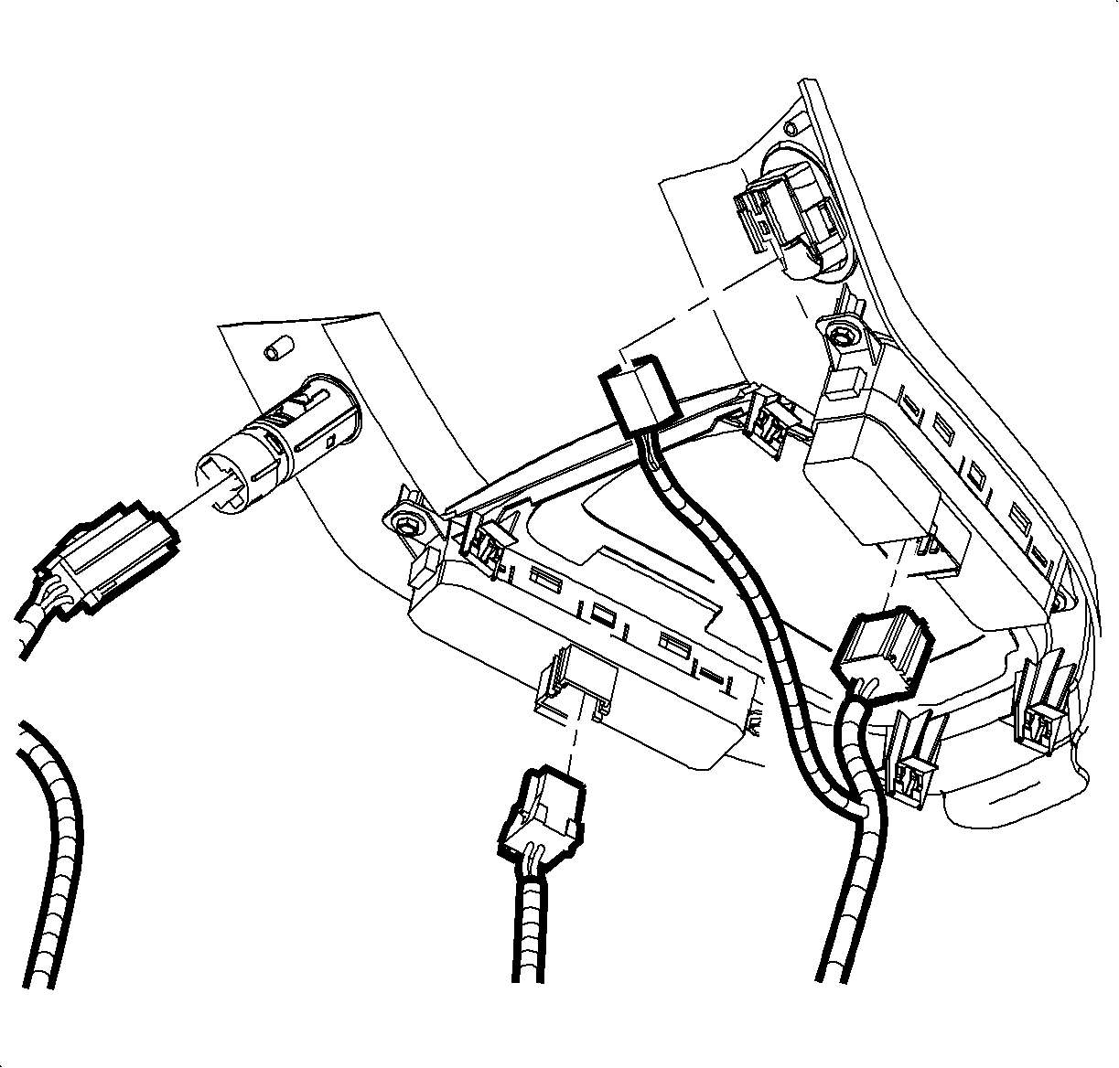
- Beginning at the rearward edge, pull to remove the shift lever bezel. from the center console
- Disconnect the bezel electrical connectors.
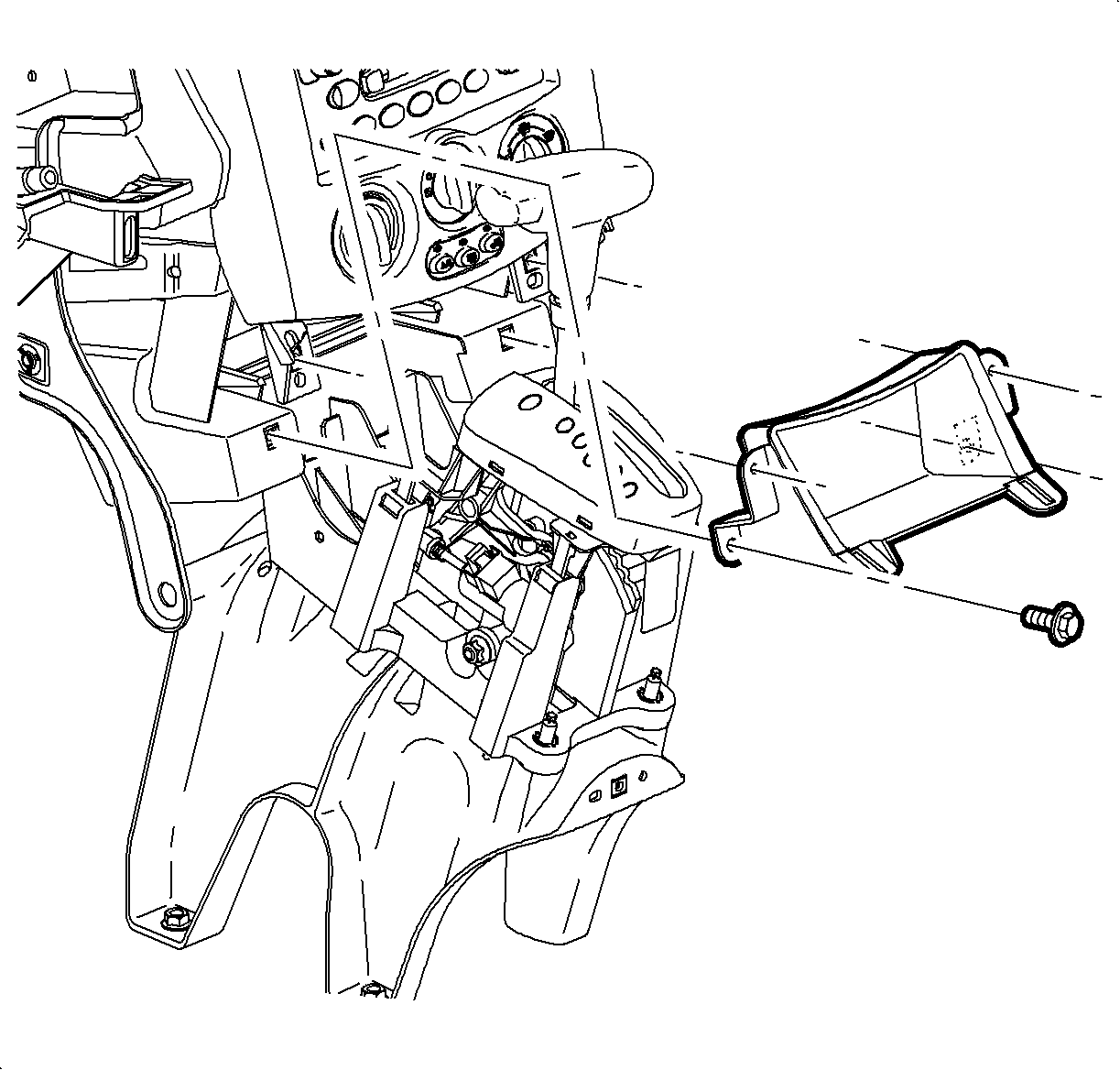
- Remove the center storage compartment screws.
- Remove the storage compartment.
- Remove the center trim bezel. Refer to Instrument Panel Accessory Bezel Replacement .
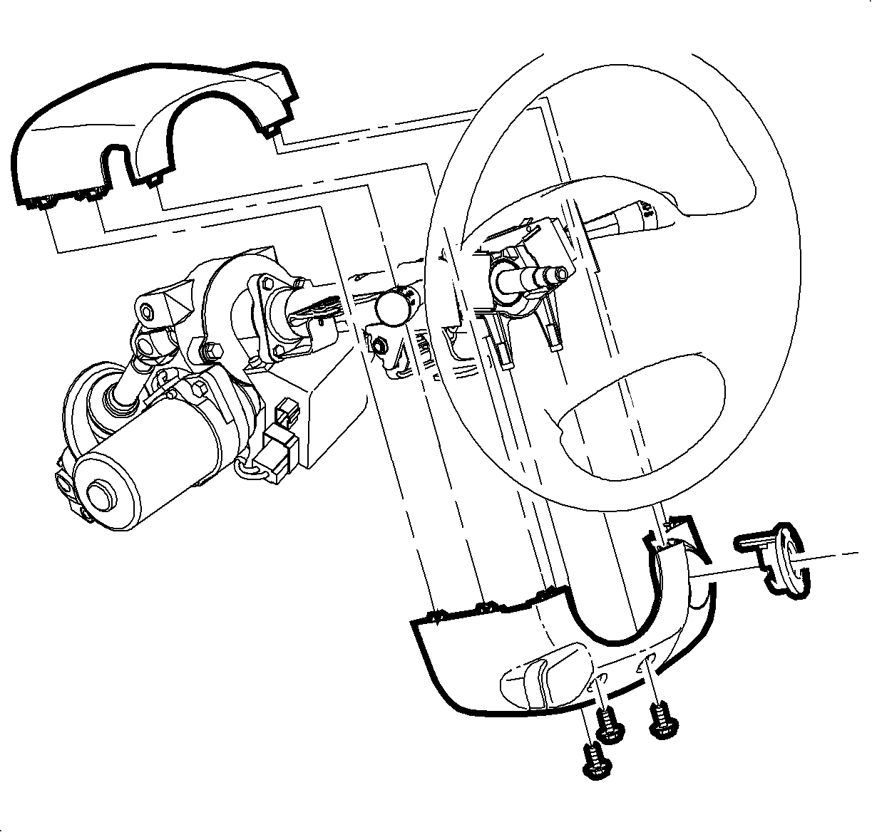
- Using a small, flat-bladed tool, pry off the ignition bezel.
- Remove the screws from the steering column shroud.
- Remove the upper shroud.
- Remove the lower shroud.
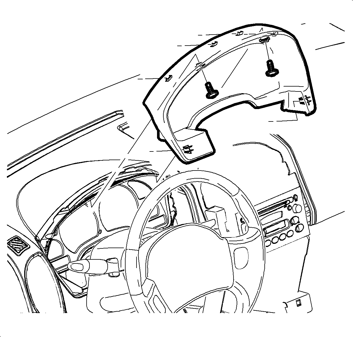
- Remove the I/P cluster trim panel screw.
- Pull to remove the cluster trim.
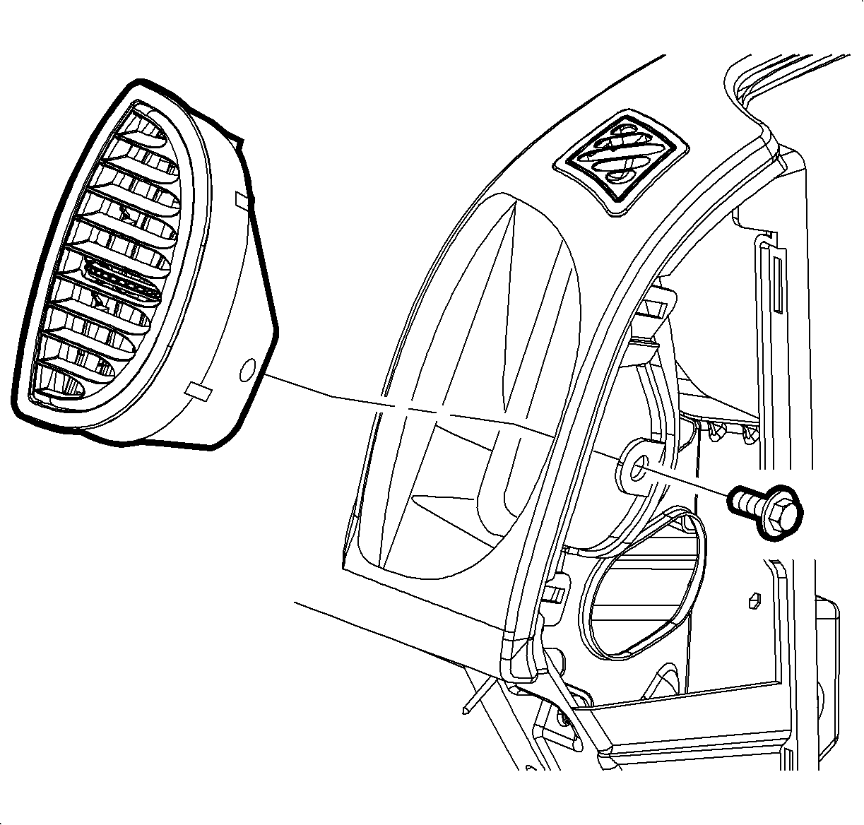
- Remove the screw from the right air outlet.
- If equipped, remove the ambient light sensor. Refer to Ambient Light Sensor Replacement .
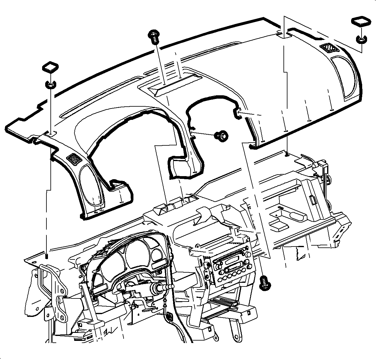
- Using a small, flat-bladed tool, pry off the trim panel bolt covers.
- Remove the bolts from the I/P upper trim panel.
- Remove the screws from the I/P upper trim panel.
- Remove the I/P upper trim panel from the vehicle.
Caution: Refer to SIR Inflator Module Handling and Storage Caution in the Preface section.
Caution: Refer to SIR Caution in the Preface section.
Caution: A deployed dual stage inflator module will look the same whether one or both stages were used, always assume a deployed dual stage inflator module has an active stage 2. Improper handling or servicing can activate the inflator module and cause personal injury.
Installation Procedure
- Position the I/P upper trim panel in the vehicle.
- Install the bolts to the I/P upper trim panel.
- Install the trim panel bolt covers.
- Install the screws to the I/P upper trim panel.
- Install the right air outlet screw.
- Position the I/P cluster trim panel.
- Push to install the trim panel in the vehicle.
- Install the screws to the I/P cluster trim panel.
- Position the upper steering column shroud.
- Position the lower steering column shroud.
- Install the shroud by pressing the parts together.
- Position the ignition bezel and install by pushing the bezel into place.
- Install the screws to the steering column shroud.
- Install the center trim bezel. Refer to Instrument Panel Accessory Bezel Replacement .
- Position the center storage compartment.
- Install the screws to the center storage compartment.
- Connect the electrical connectors to the shift lever bezel on the center console.
- Position the lever bezel and press to install the bezel.
- Install the right I/P outer trim cover.
- Connect the electrical connector to the left doorjamb switch.
- Position the left I/P outer trim cover and press to install the cover.
- Position the steering column filler panel and press to install the panel.
- Install the filler panel screws.
- Install the windshield garnish moldings. Refer to Windshield Upper Garnish Molding Replacement .
- Enable the frontal SIR system. Refer to SIR Disabling and Enabling in SIR.

Notice: Refer to Fastener Notice in the Preface section.
Tighten
Tighten the bolts to 10 N·m (89 lb in).
Tighten
Tighten the bolts to 2.5 N·m (22 lb in).

Tighten
Tighten the bolts to 2 N·m (18 lb in).

Tighten
Tighten the bolts to 2.5 N·m (22 lb in).

Tighten
Tighten the bolts to 2.5 N·m (22 lb in).

Tighten
Tighten the bolts to 2.5 N·m (22 lb in).


Tighten
Tighten the bolts to 2.5 N·m (22 lb in).
