Special Tools
| • | J 36346 Fascia Retainer Remover |
| • | J 44015 Steering Linkage Installer |
| • | J 44017 Stub Shaft Assembly Remover |
| • | J 45341 Rear Wheel Drive Shaft Removal Tool |
| • | SA9105E Engine Support Fixture - 3-Bar |
| • | SA91112T Axle Seal Protector |
| • | SA9133T Axle Seal Puller |
| • | SA9173G Slide Hammer |
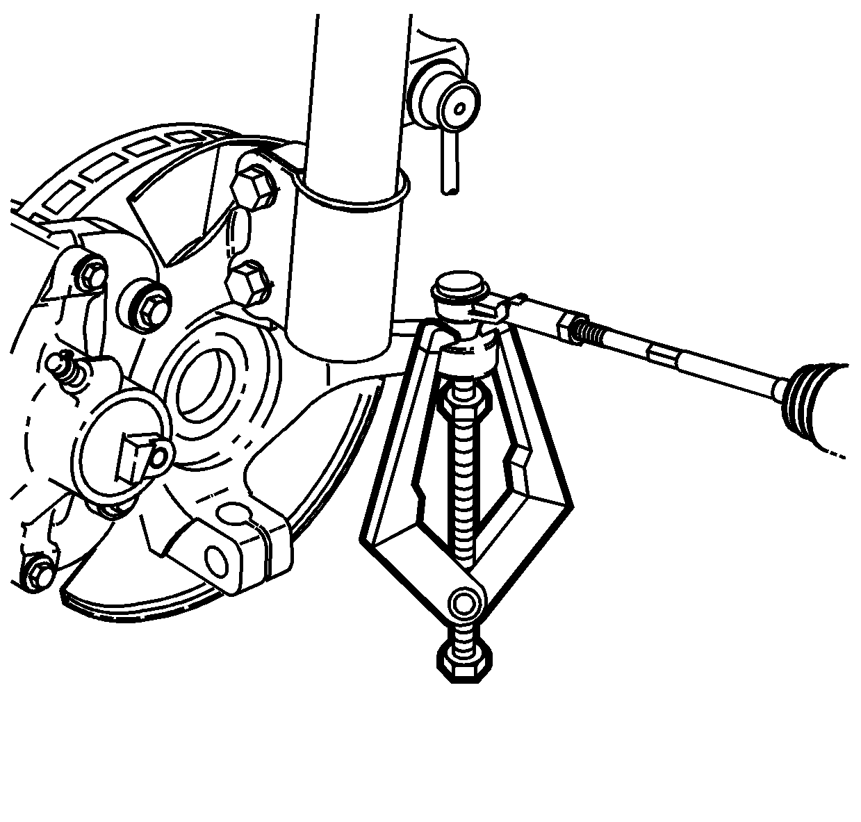
| • | SA91100C Tie Rod Separator |
Removal Procedure
- Remove the battery cover.
- Disconnect the negative battery cable. Refer to Battery Negative Cable Disconnection and Connection .
- Disconnect the positive battery cable.
- Loosen the battery hold down screw and remove the battery.
- Remove the battery cooling box. Refer to Battery Box Replacement .
- Loosen the battery tray bracket screws and remove the bracket.
- Remove the air induction resonator.
- Remove the air induction resonator bracket.
- Using the J 36346 , disconnect the shifter cable from the transmission range switch lever.
- Disconnect the shifter cable from the shifter cable bracket.
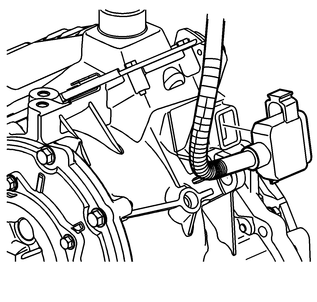
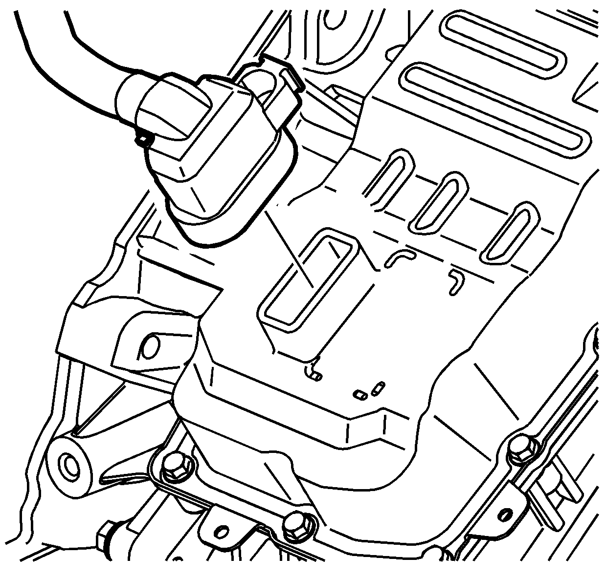
- Disconnect the transmission range switch harness from the transmission range switch.
- Disconnect the transmission harness connector from the valve body.
- Remove the headlamp fasteners.
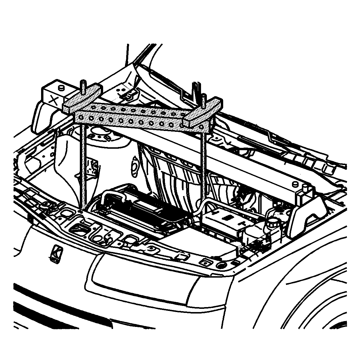
- Wire the radiator to the radiator core support in order to hold the radiator in place as the cradle is removed.
- Install the SA9105E .
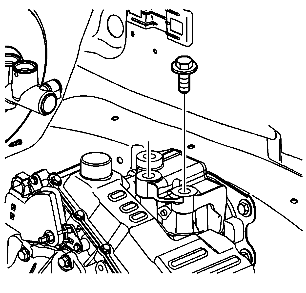
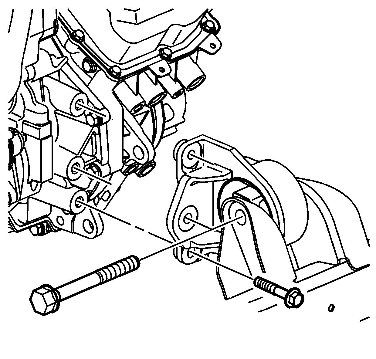
- Remove 1 upper transmission-to-engine bolt.
- Remove the upper left transmission mount bolts.
- Raise and support the vehicle. Refer to Lifting and Jacking the Vehicle .
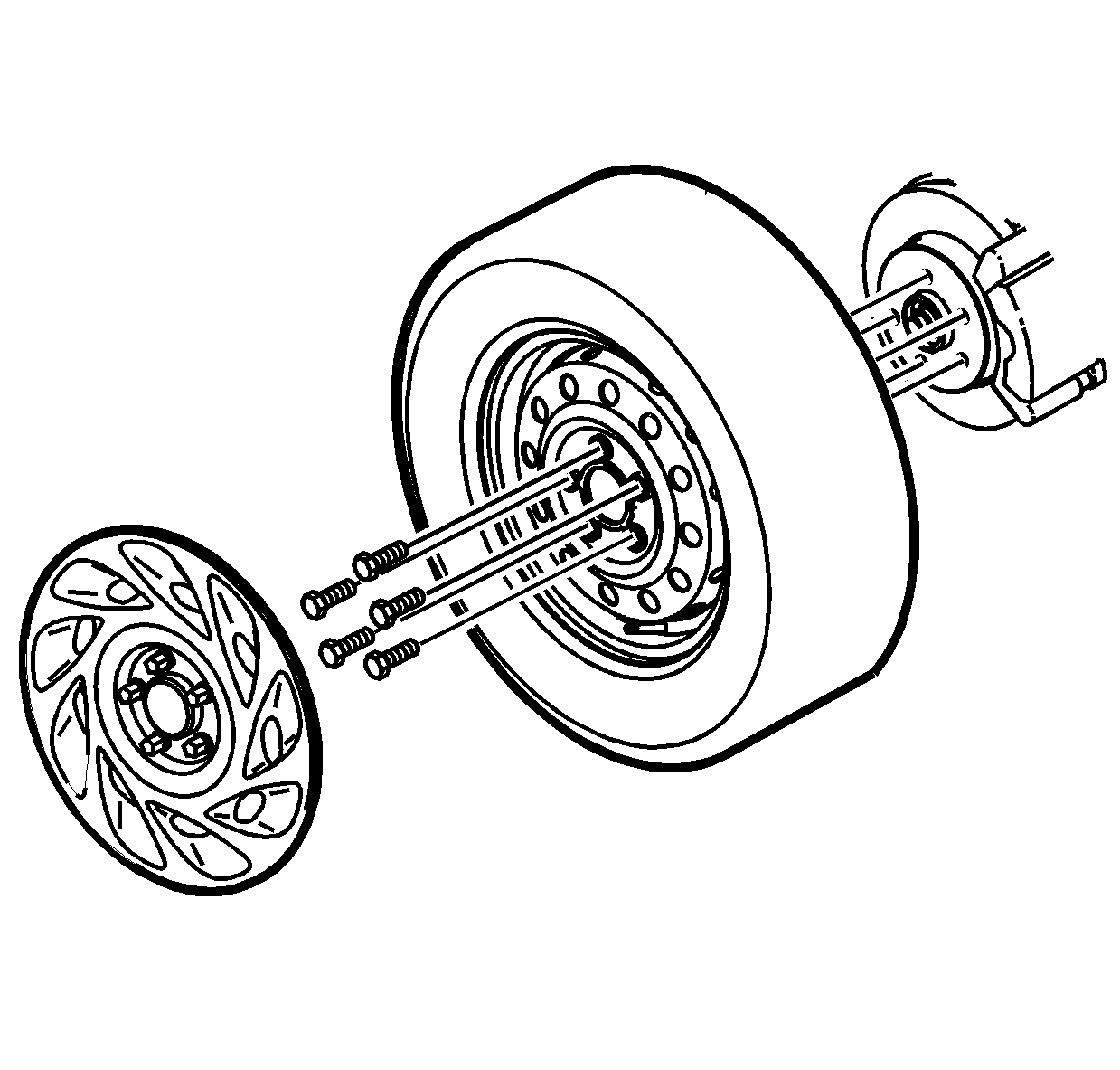
- Remove the right wheel and tire assembly.
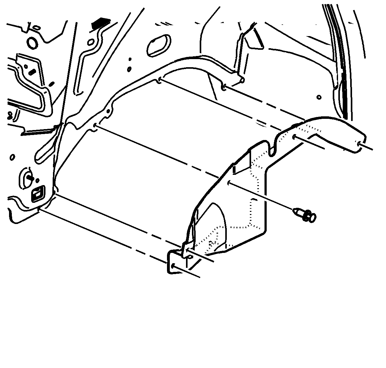
- Remove the left inner splash shield.
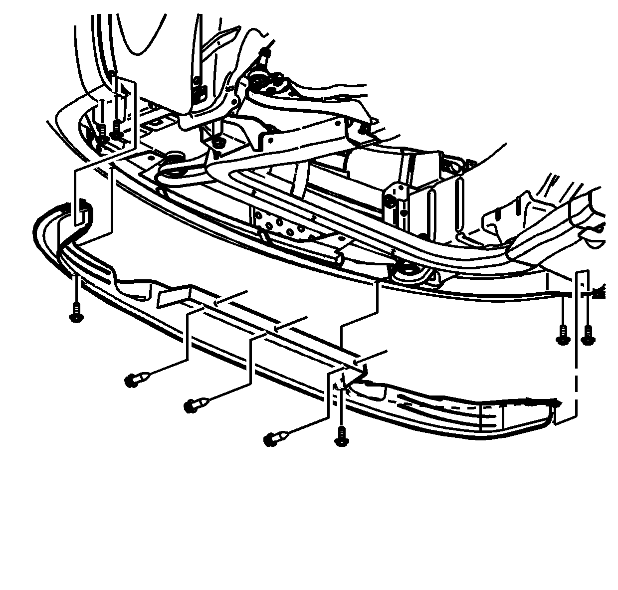
- Remove the front air deflector-to-cradle pushpins.
- Remove the lower tube assembly and drain the fluid.
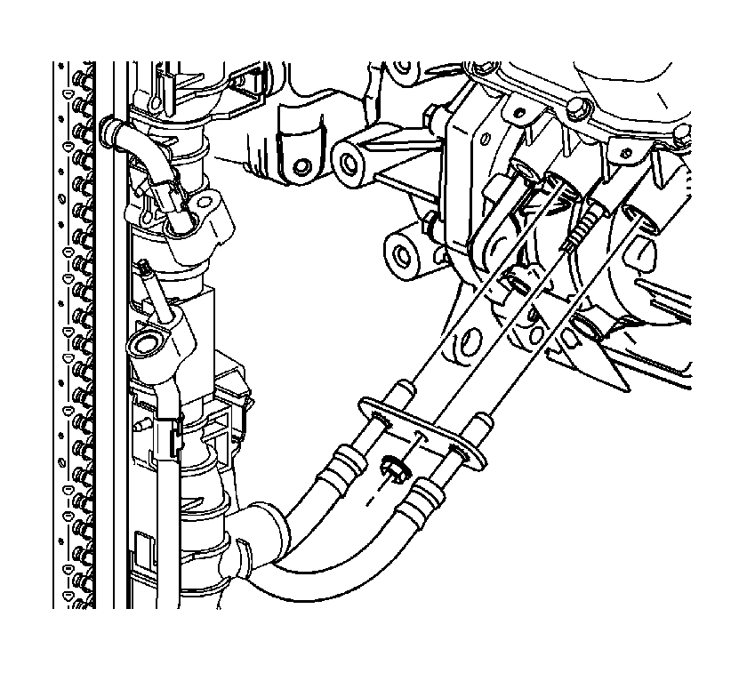
- Remove the transmission oil cooler line assembly nut from the transmission.
- Remove the transmission oil cooler lines from the transmission.
- For all-wheel drive (AWD) vehicles, disconnect the drive shaft from the power take-off unit (PTU) and support the drive shaft. Mark the alignment position of the PTU and the drive shaft.
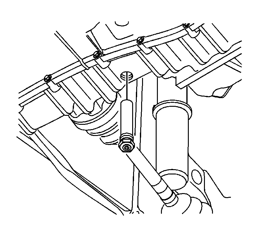
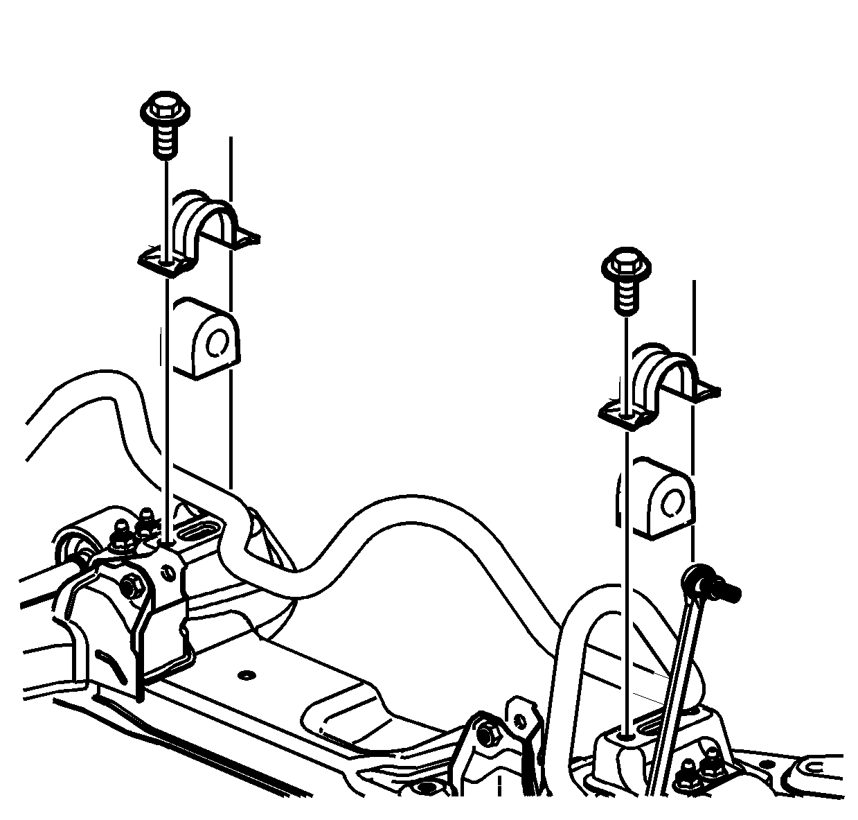
- Disconnect the lower stabilizer nut from the cradle on both sides of vehicle.
- Remove the rack and pinion bolts from the cradle.
- Remove the lower control arm ball stud cotter pin and nut. Discard the pin.
- Separate the ball stud from the knuckle.
- Remove the outer tie rod-to-knuckle nut. Discard the nut.
- Using the SA91100C or equivalent, separate the tie rod from the knuckle.
- Remove the front pitch restrictor bolts and front pitch restrictor.
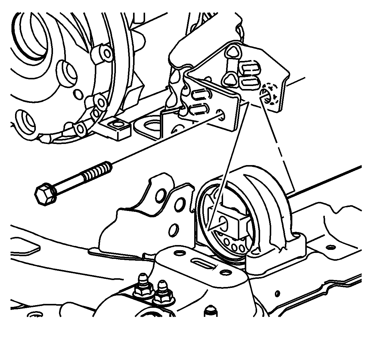
- Remove the rear pitch restrictor through-bolt.
- Support the cradle with cradle support.
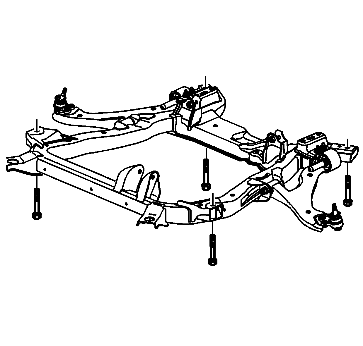
- Remove the cradle fasteners and lower the cradle onto a support table.
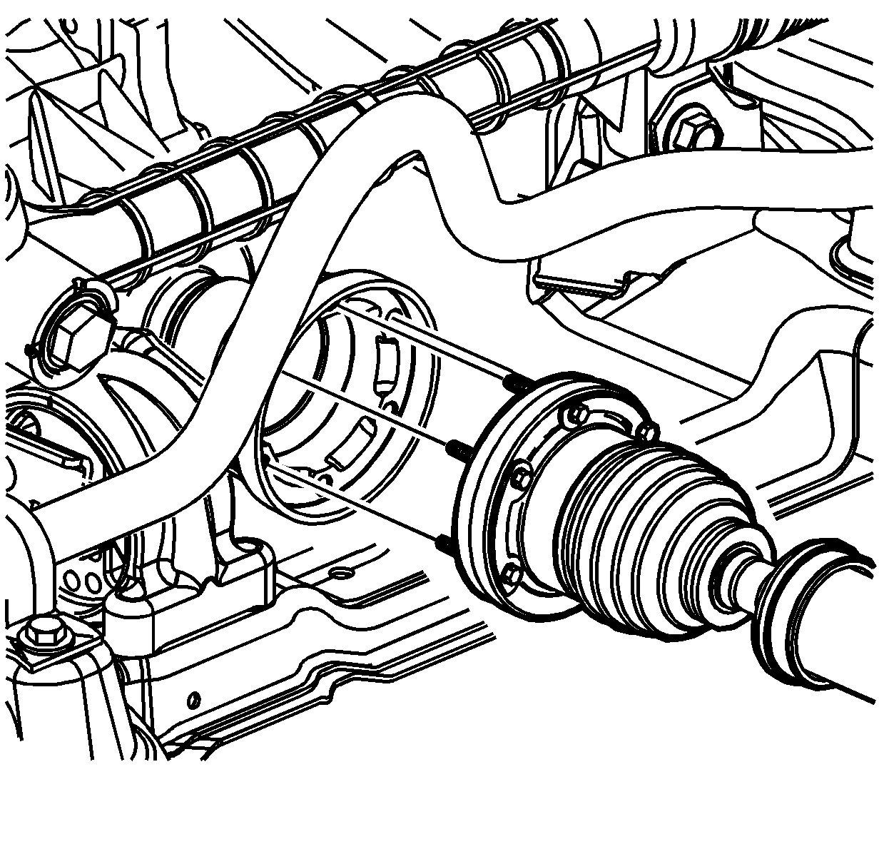
- Using the J 45341 and the SA9173G , separate the left axle shaft from the transmission. Use a tie strap to keep the axle out of the way.
- For front wheel drive (FWD) vehicles, separate the right axle shaft from the intermediate drive shaft.
- For FWD vehicles, remove the intermediate drive shaft bearing retainer to intermediate drive shaft support bracket bolts.
- For FWD vehicles, separate the intermediate drive shaft from the transmission. If the shaft is difficult to remove, use the J 44017 and the SA9133T .
- For AWD vehicles, using the J 45341 and the SA9173G , separate the right axle shaft from the PTU.
- Remove the axle shaft O-ring seal. Discard the seal.
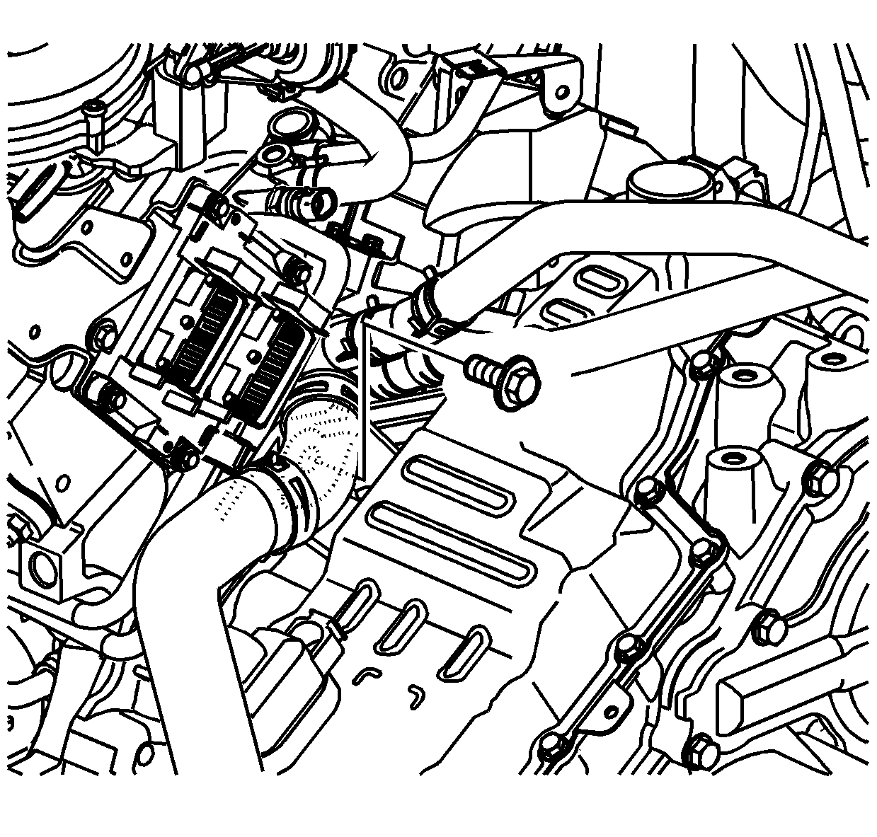
- Remove the starter wiring harness.
- Remove the starter bolts and starter.
- Turn the crank clockwise to gain access to the torque converter-to-flexplate bolts.
- Remove the torque converter-to-flexplate bolts through the starter hole.
- For AWD vehicles, remove the PTU-to-engine bracket assembly.
- Remove the PTU vent hose.
- For AWD vehicles, remove the PTU bolts and separate the PTU from the transmission.
- For AWD vehicles, remove the stub shaft from the transmission if not already removed.
- Secure the transmission to a transmission jack.
- Remove the lower transmission-to-engine bolts.
- Separate the transmission from the engine.
- Lower the transmission carefully.
- Remove the torque converter and differential housing O-ring seal. Discard the seal.
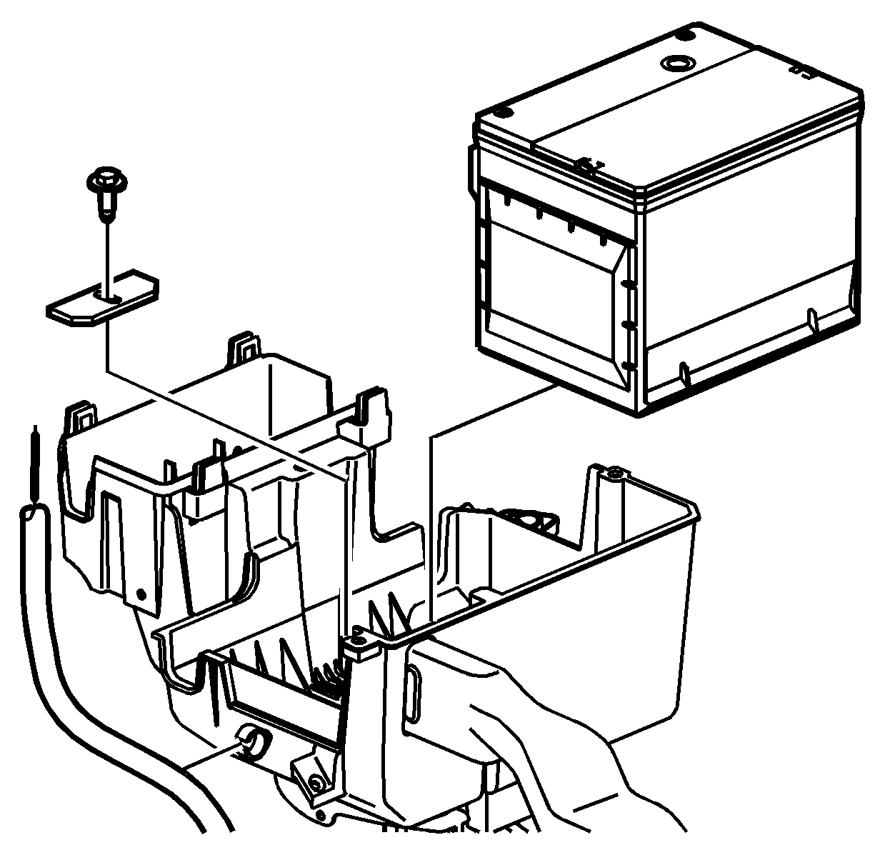
Caution: Refer to Battery Disconnect Caution in the Preface section.
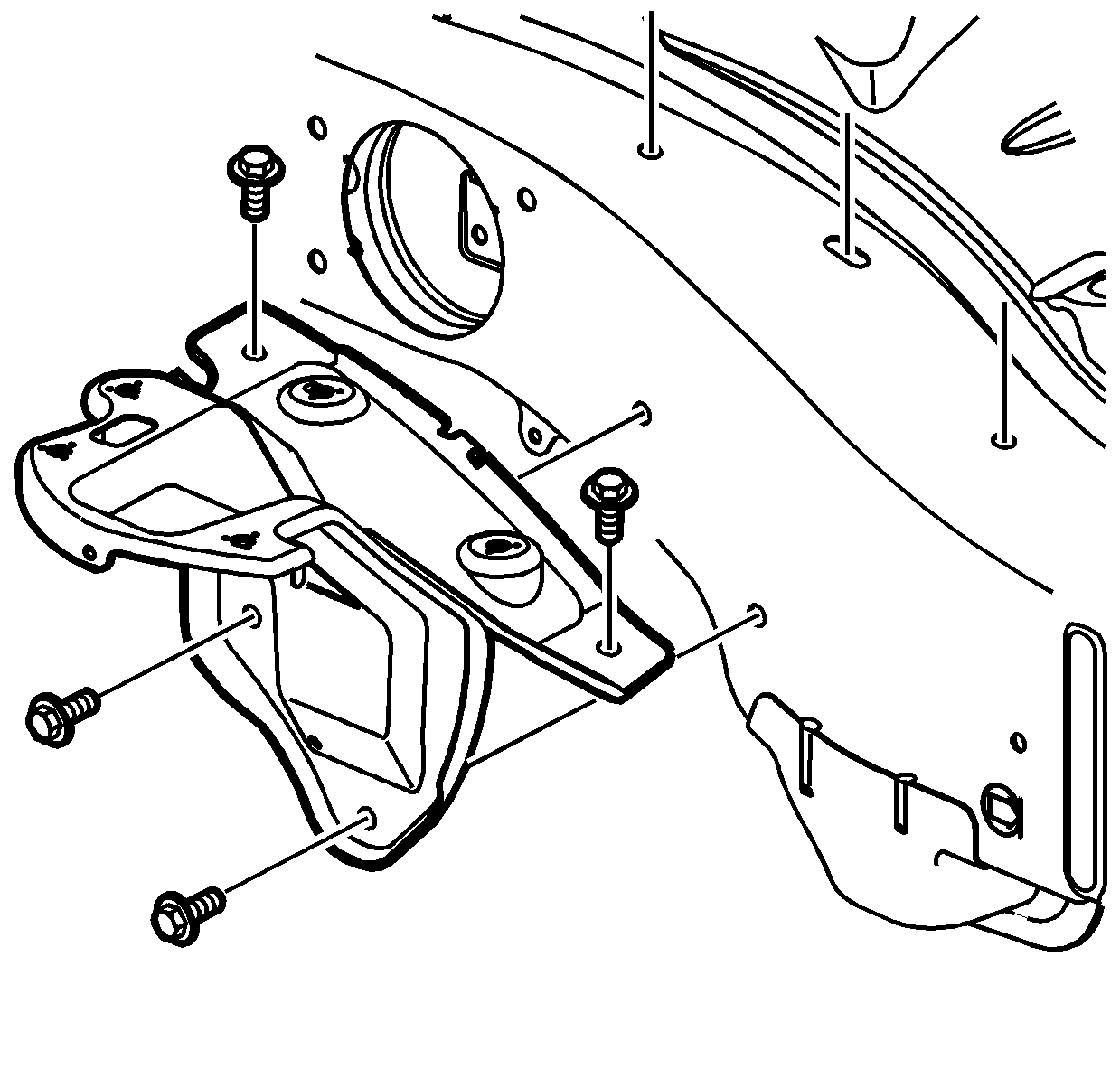
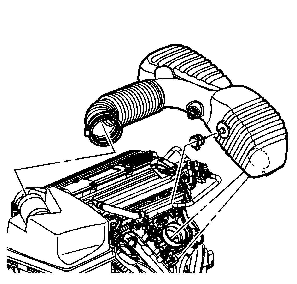
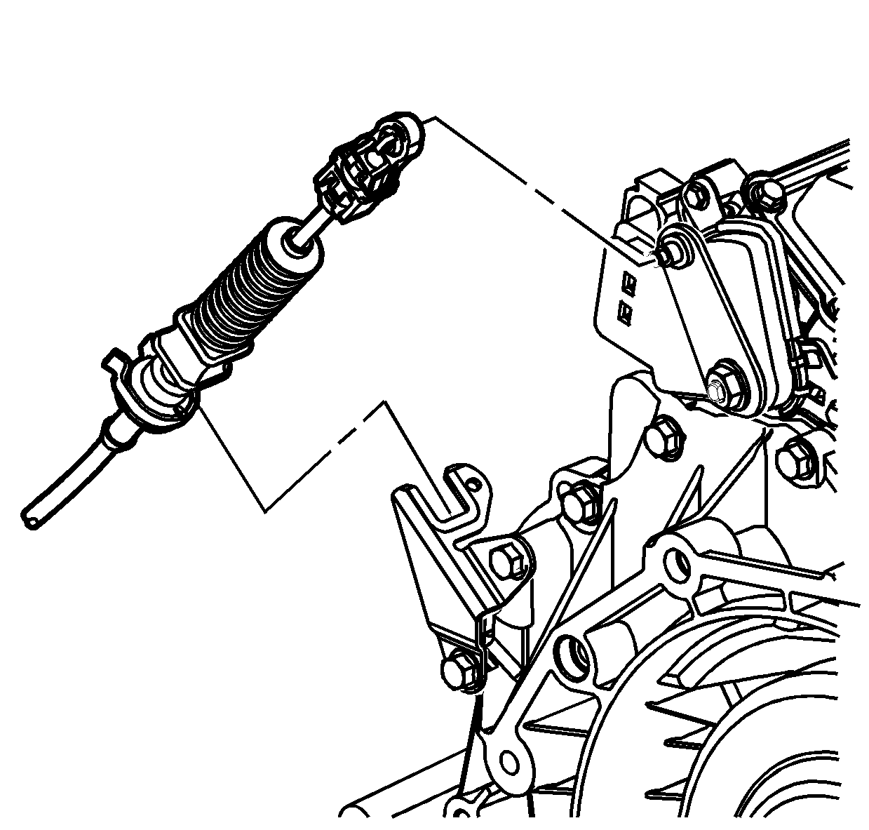
Notice: The control cable must be disconnected from the transaxle range switch lever prior to disconnecting it from the control cable bracket. Otherwise damage to the manual shift shaft may result, requiring transaxle disassembly.
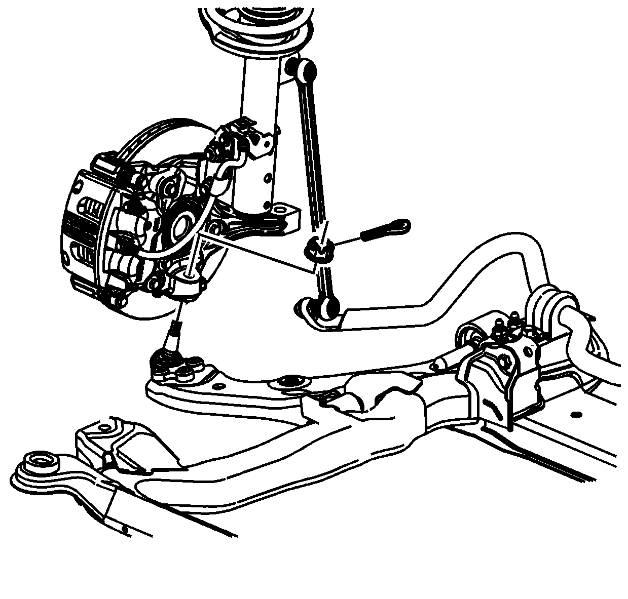
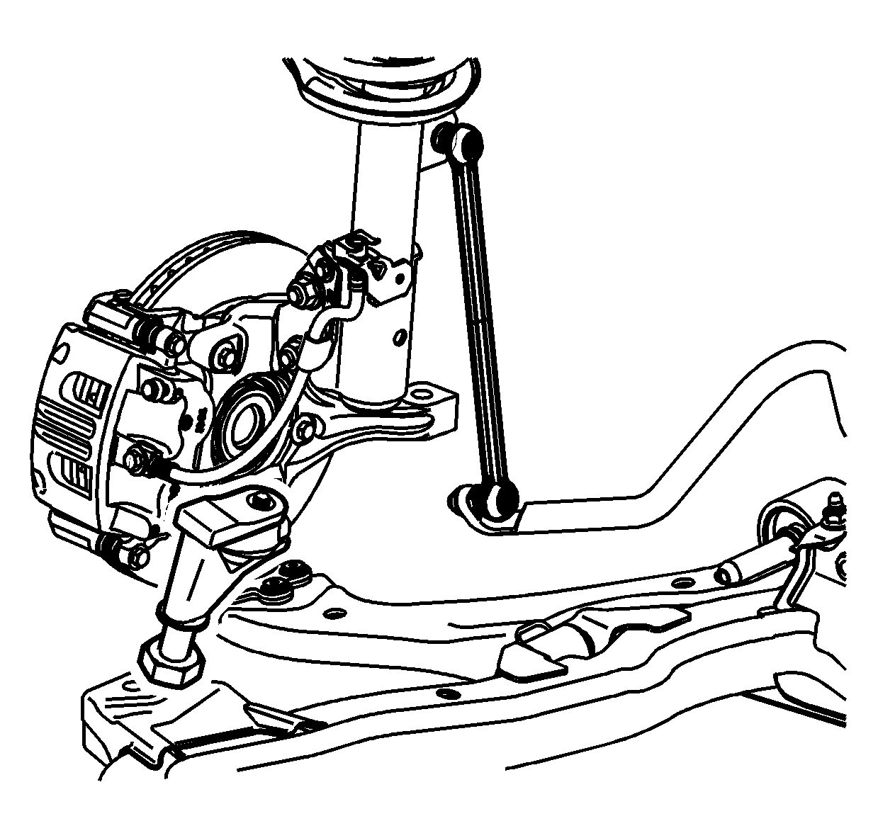
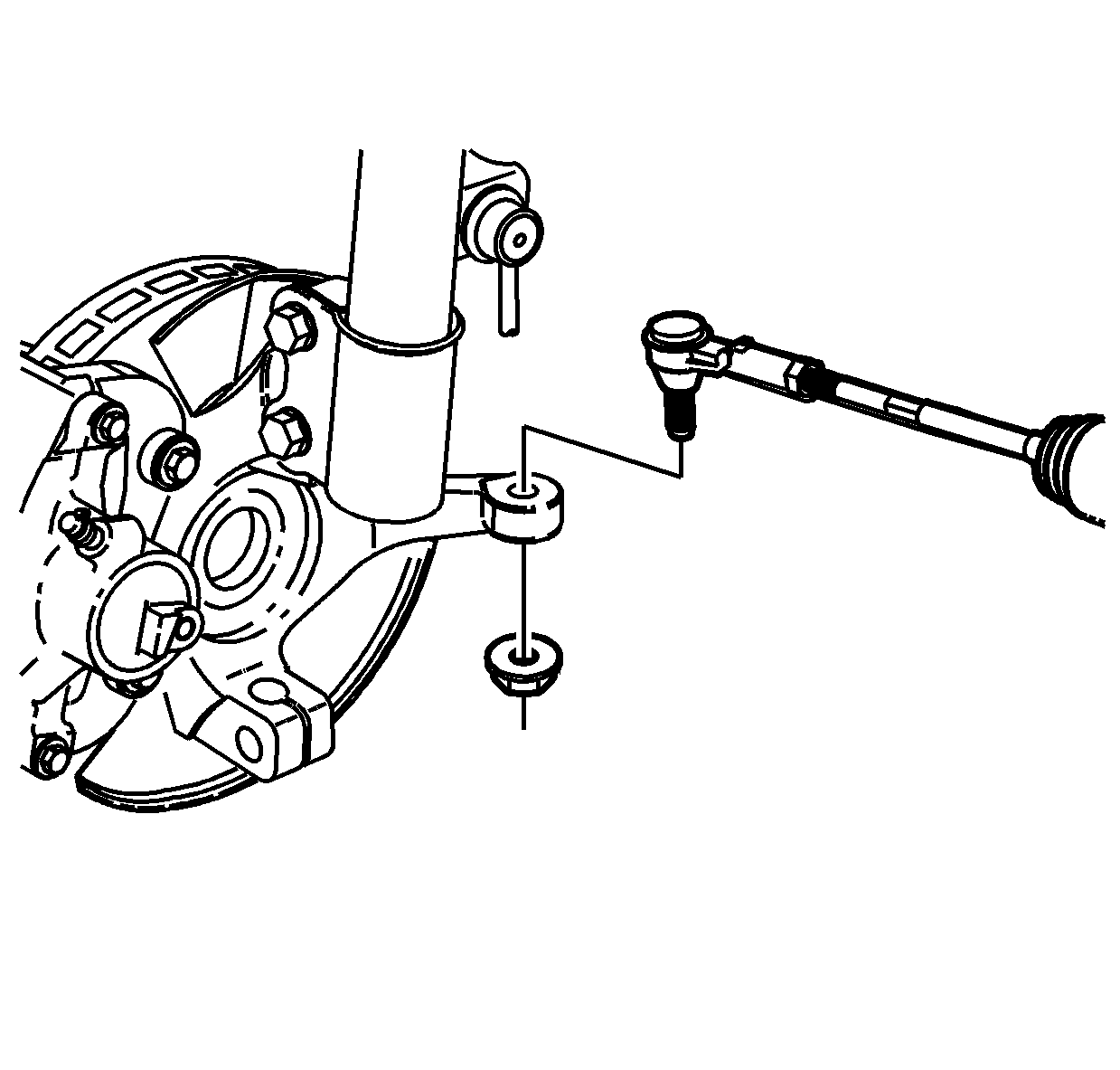
Notice: Hold the ball stud from turning when removing/installing the nut. The boot can become torn and damaged if the ball stud turns.
Notice: Do not attempt to separate the joint using a wedge-type tool because seal may be damaged.
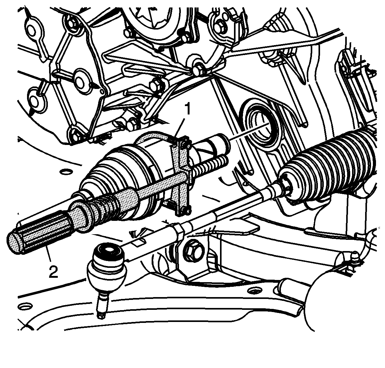
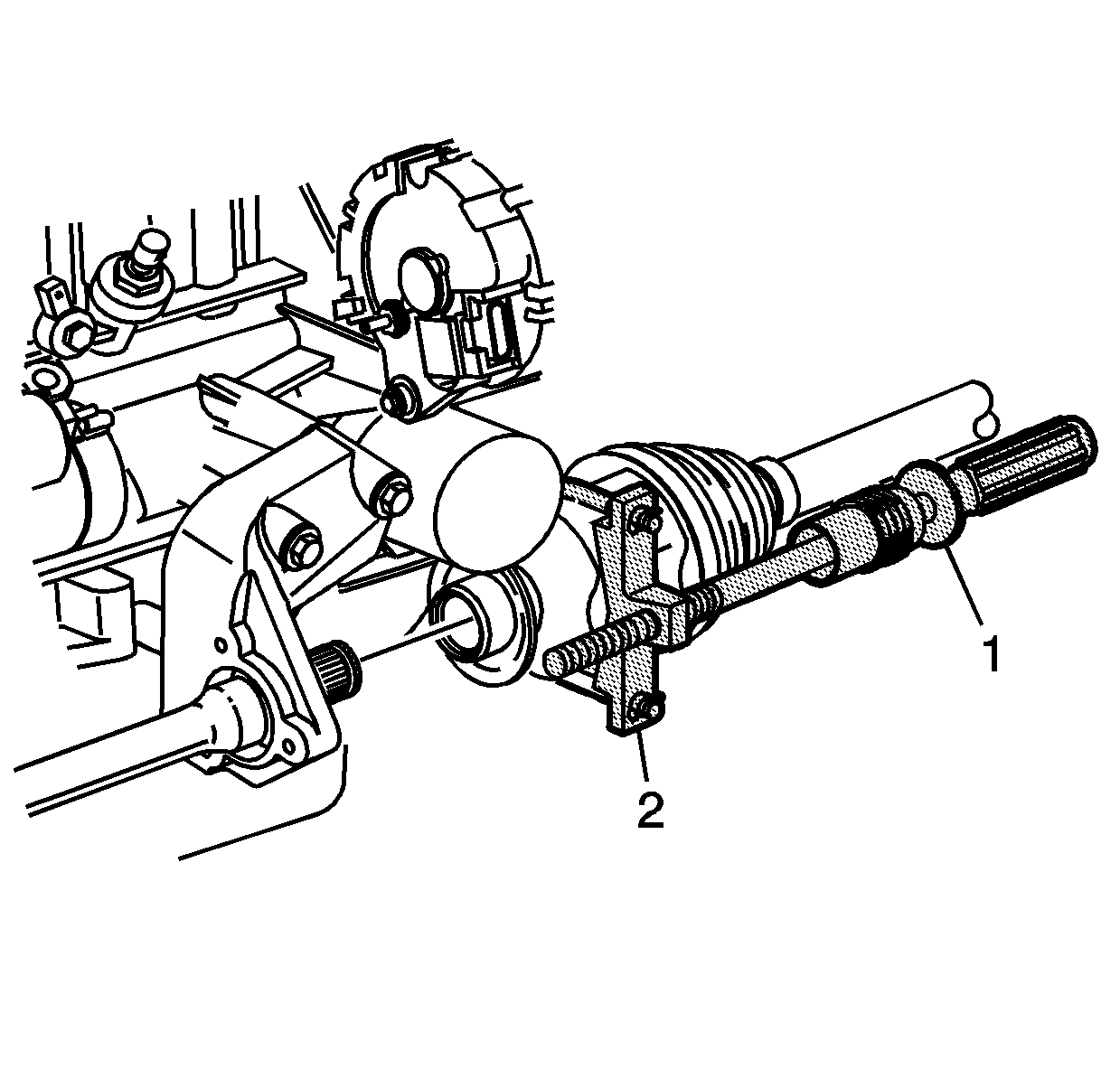
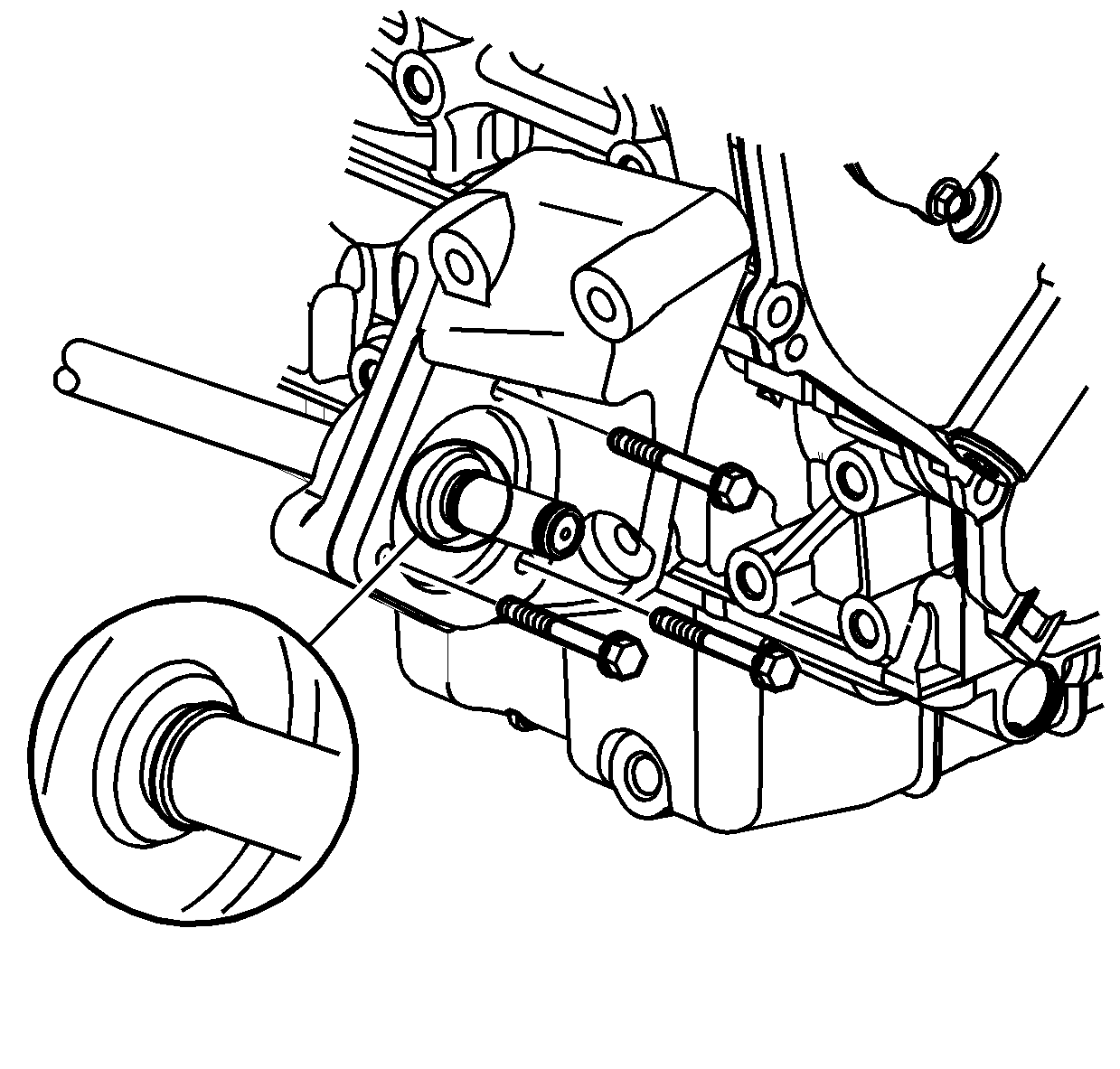
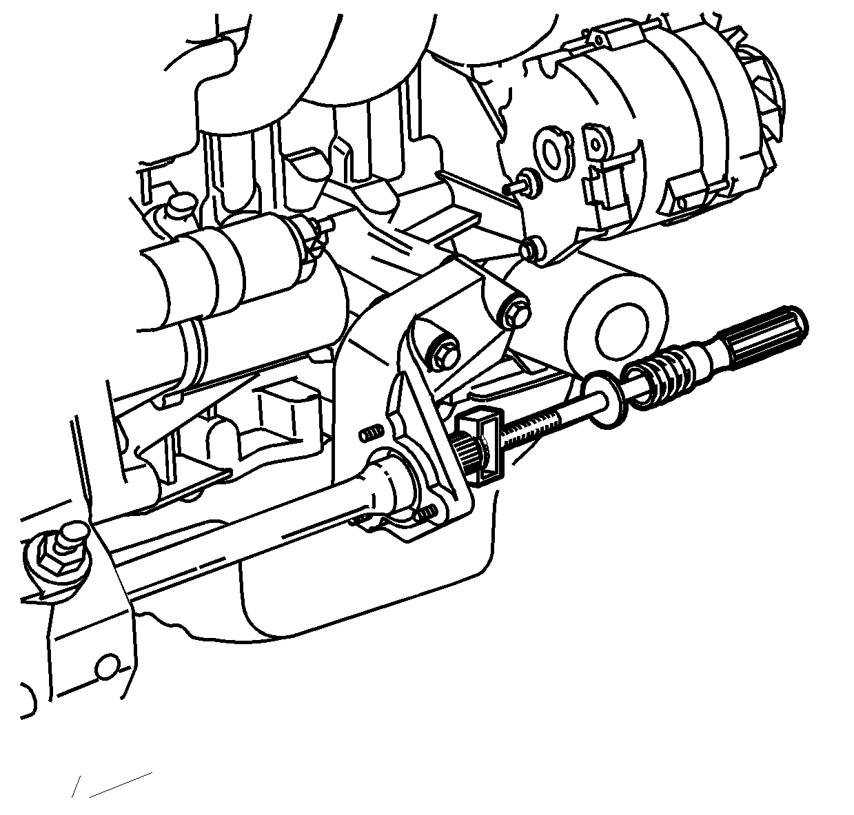
Important: Remove the retaining ring from the stub shaft prior to tool installation. Discard the ring.
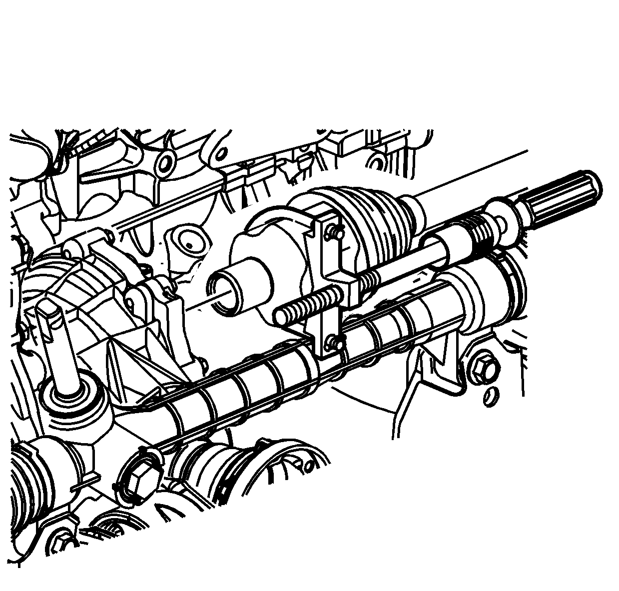
Important: If the stub shaft disengages from the PTU, separate the PTU from the axle and plug the stub shaft hole to prevent fluid loss.
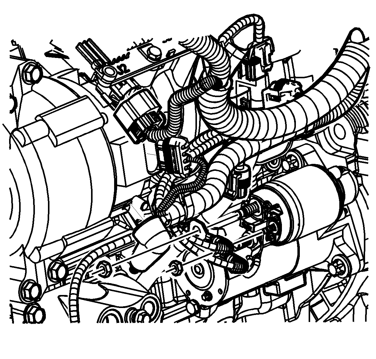
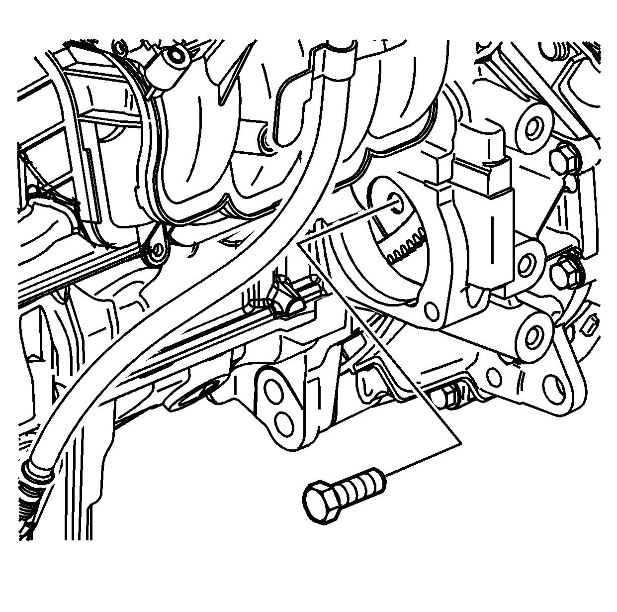
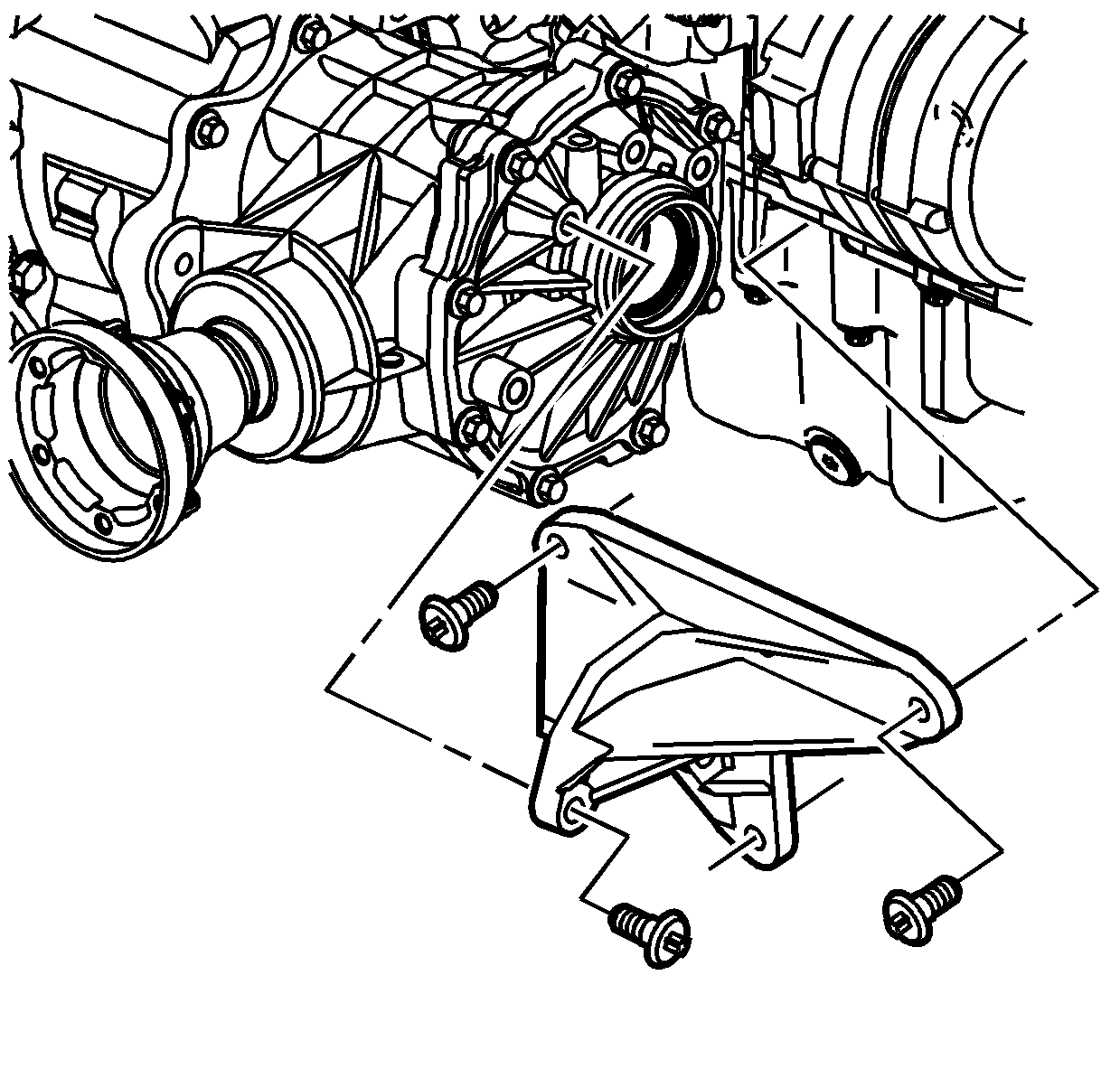
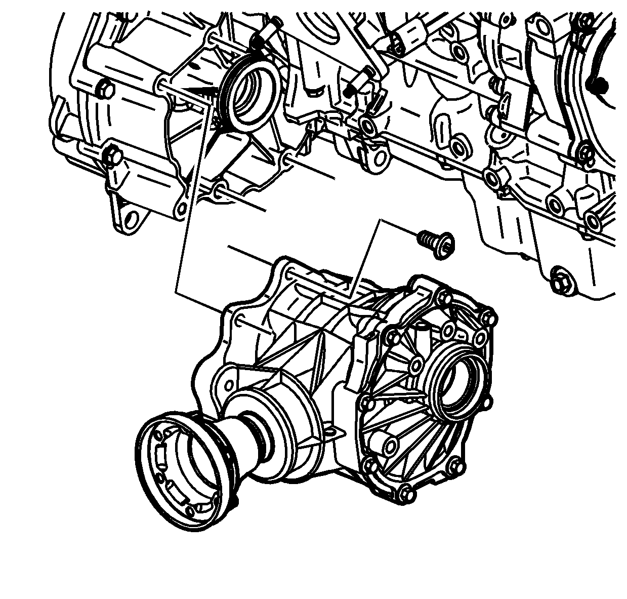
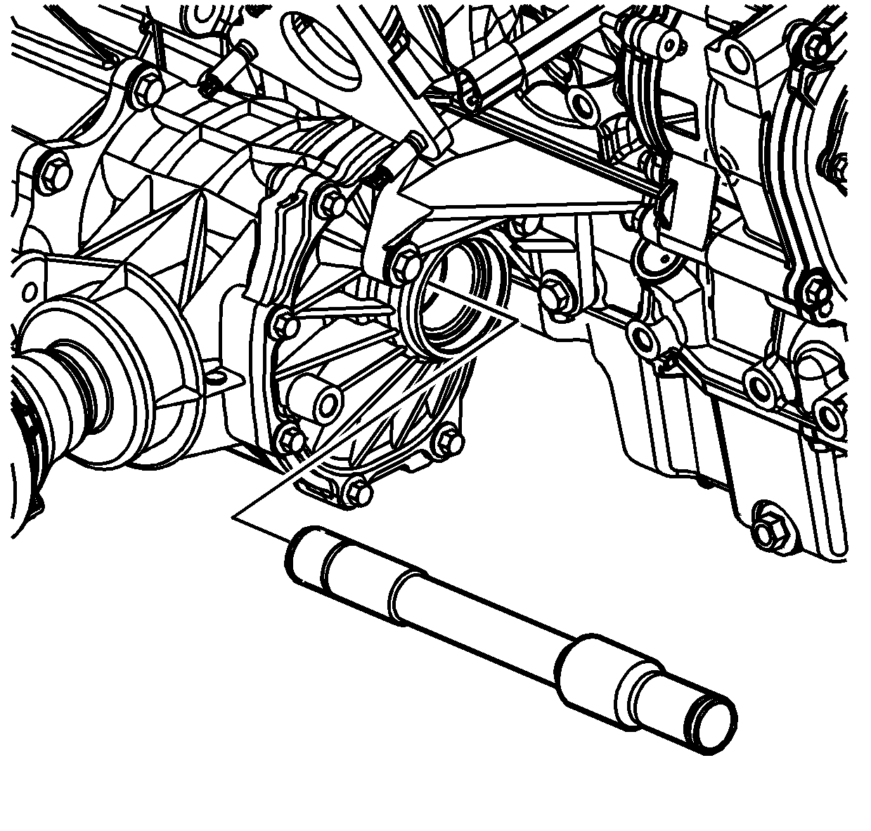
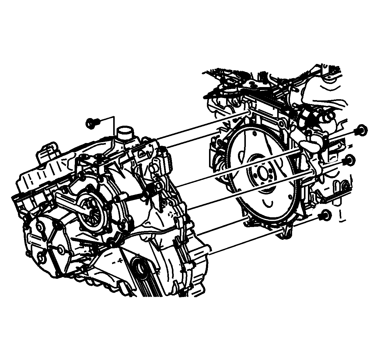
Important:
• The torque converter has a long pilot shaft. Do not put excessive load on the shaft. Do not lower the transmission until the shaft is clear of the engine crankshaft. • Do not damage the mating surfaces of the engine or transmission.
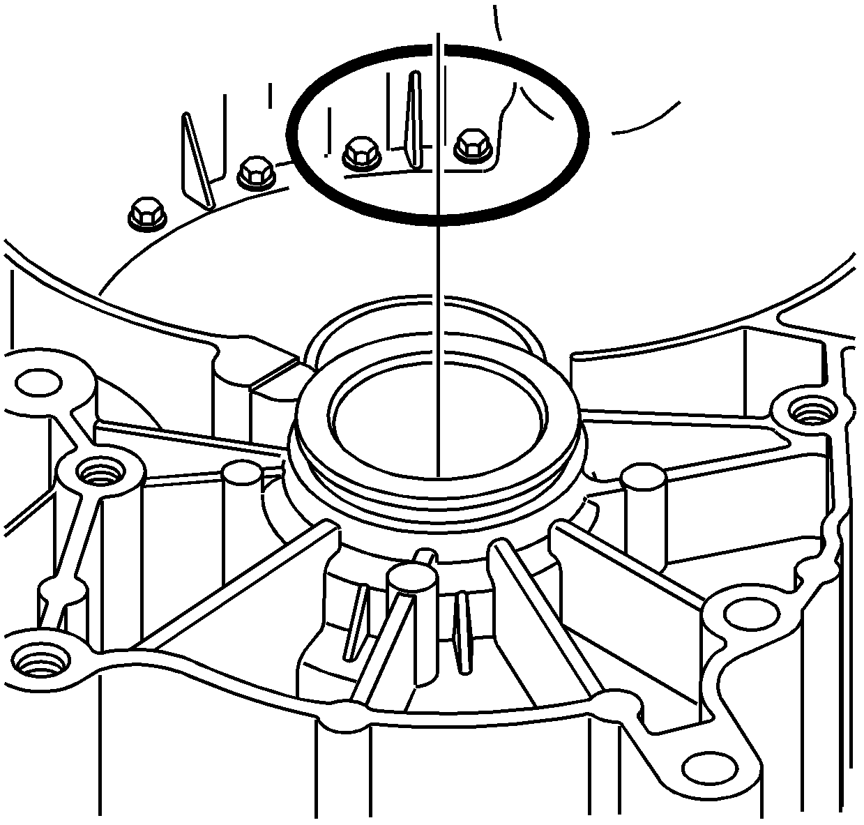
Installation Procedure
- For AWD vehicles, install a new torque converter and differential housing O-ring seal.
- With the transmission supported, carefully raise the transmission.
- Install the engine to the transmission.
- Install the lower transmission-to-engine bolts.
- For AWD vehicles, install new retaining rings on the stub shaft.
- For AWD vehicles, install the stub shaft into the transmission
- For AWD vehicles, install the PTU and bolts to the transmission.
- For AWD vehicles, install the PTU-to-engine bracket assembly.
- Rotate the crank and align the net hole of the flexplate through the starter opening.
- Install the torque converter-to-flexplate bolts through the starter opening.
- Install the starter and the starter bolts.
- Install the starter wiring harness.
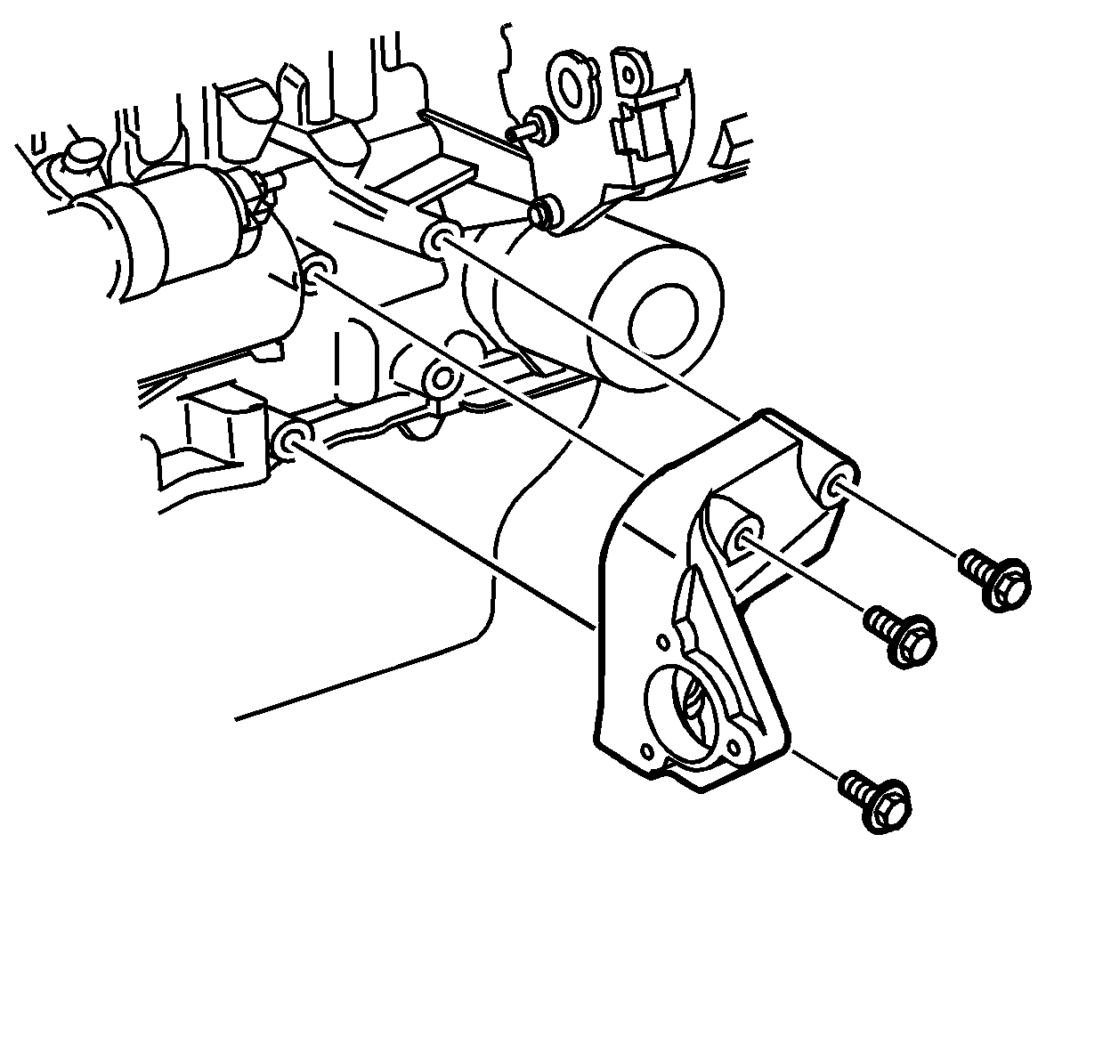
- For FWD vehicles, install the SA91112T inside the seal.
- For FWD vehicles, position the bracket to the engine and hand start the bolts, then tighten.
- For FWD vehicles, lubricate the axle with Saturn DEX-CVT® fluid P/N 22688912.
- For FWD vehicles, install the intermediate drive shaft into the transmission.
- For FWD vehicles, remove the SA91112T after the splines clear the SA91112T , but before the intermediate drive shaft is fully installed.
- For FWD vehicles, push the intermediate drive shaft all the way into the transmission.
- For FWD vehicles, install a new retaining ring to the intermediate drive shaft.
- For FWD vehicles, install the right axle shaft to the intermediate drive shaft.
- For AWD vehicles, install a new axle shaft O-ring.
- For AWD vehicles, install the right axle shaft the PTU shaft.
- For AWD vehicles, install a new retaining ring on the left axle shaft.
- For AWD vehicles, install the SA91112T inside the seal.
- For AWD vehicles, lubricate the axle with Saturn DEX-CVT® fluid P/N 22688912.
- For AWD vehicles, install the left axle shaft into the transmission.
- For AWD vehicles, remove the SA91112T after the splines clear the SA91112T , but before the axle shaft is fully installed.
- For AWD vehicles, push the left axle shaft all the way into the transmission.
- Support the cradle with a cradle support.
- Install the cradle and the bolts.
- Remove the support table.
- Install the rear pitch restrictor through bolt.
- Install the front pitch restrictor bolts and front pitch restrictor.
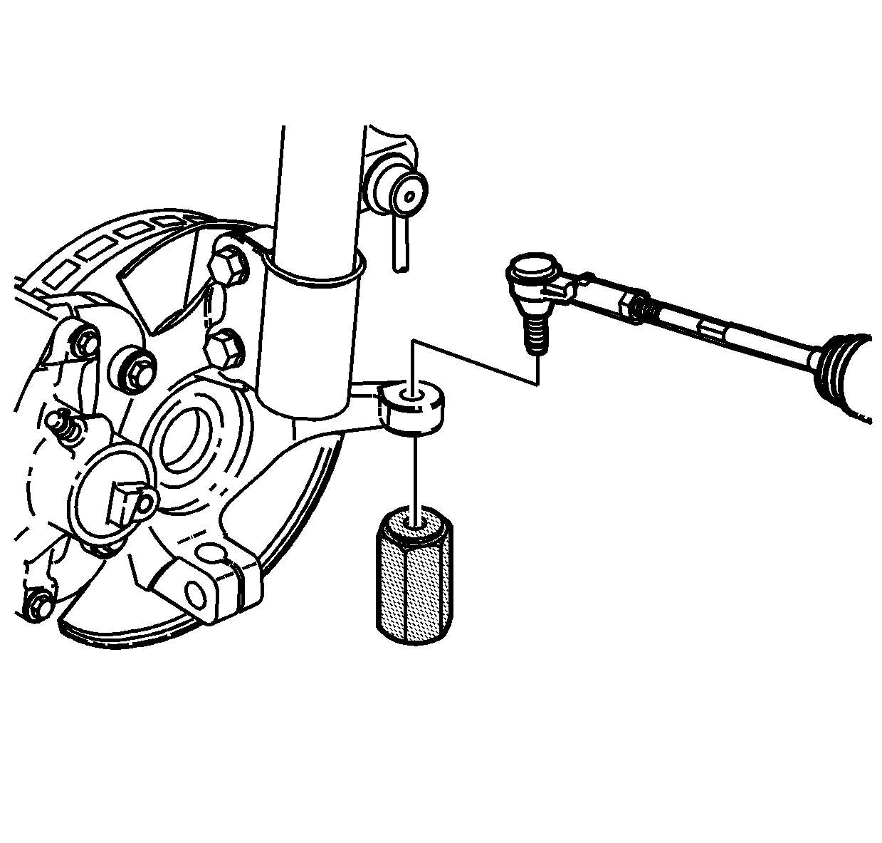
- Install the tie rod to the knuckle.
- Install the J 44015 and tighten.
- Remove the J 44015 .
- Install a new nut.
- Install the lower control arm ball stud-to-knuckle.
- Install the nut and a new cotter pin.
- Tighten the nut one additional flat to align the cotter pin hole if necessary.
- Install the rack and pinion bolts to the cradle.
- Install the lower stabilizer nuts to the cradle on both sides of the vehicle.
- For AWD vehicles, install the drive shaft to the PTU.
- If the transmission being installed is not new, the transmission oil cooler line seals must be removed and replaced. Refer to Transmission Fluid Cooler Pipe Seal Replacement .
- Install the transmission oil cooler lines and nut to the transmission.
- Install the front air dam deflector-to-cradle pushpins.
- Install the left and right inner splash shield.
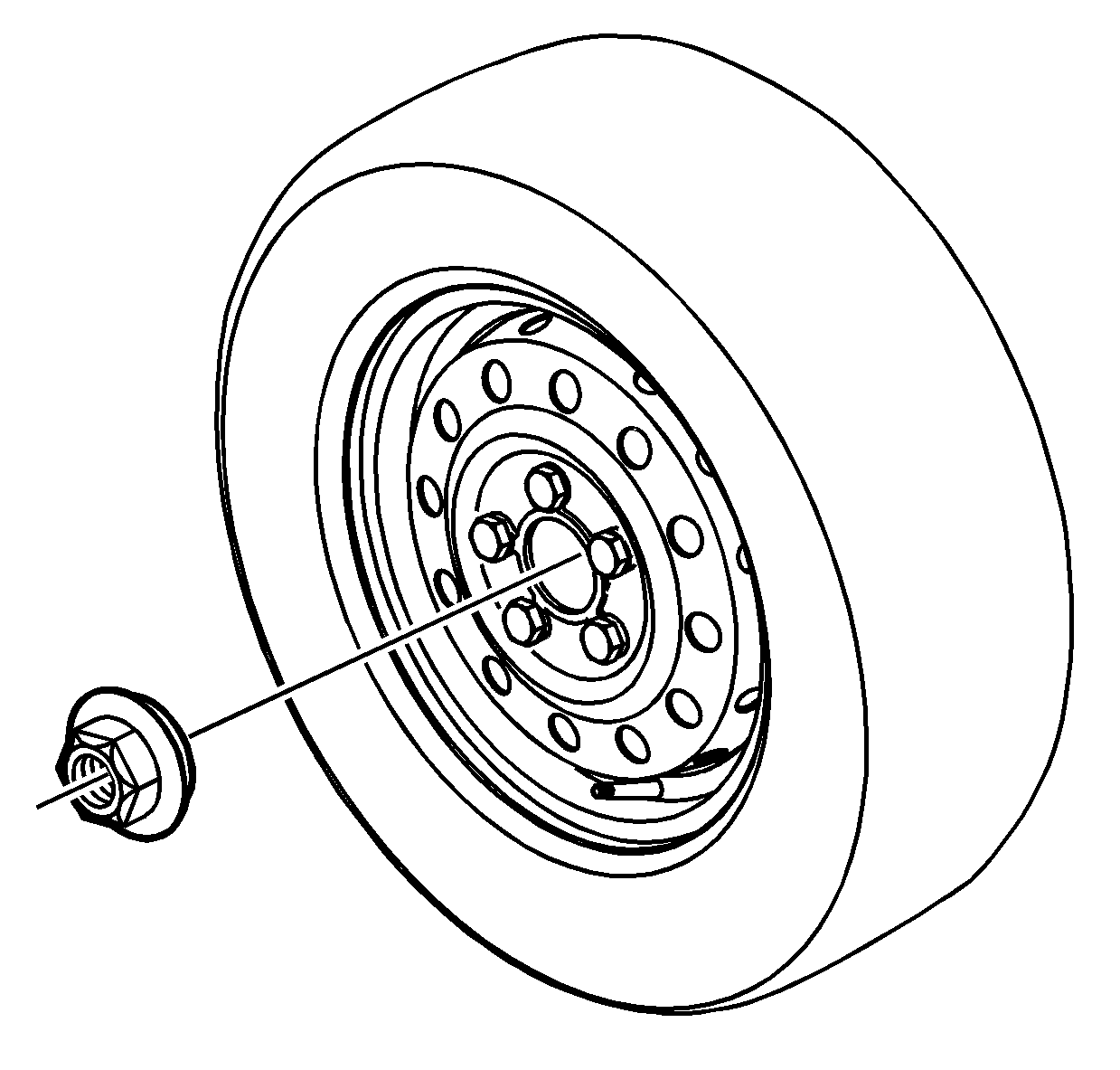
- Install the left and right wheel and tire assemblies.
- Install the axle shaft hub nut.
- Lower the vehicle.
- Install the upper left transmission mount bolts.
- Install 1 upper transmission-to-engine bolt.
- Remove the SA9105E .
- Remove the tie straps from the radiator.
- Install the transmission harness connector to the valve body.
- Install the park neutral position (PNP) switch. Refer to Park/Neutral Position Switch Replacement .
- Install the transmission range switch harness to the transmission range switch.
- Install the shifter cable to the shifter cable bracket.
- Install the shifter cable to the transmission range switch lever.
- Install the air induction resonator bracket.
- Install the air induction resonator.
- Install the battery tray bracket and screws.
- Install the battery cooling box. Refer to Battery Box Replacement .
- Install the battery and the battery hold down screw.
- Connect the positive battery cable to the battery.
- Connect the negative battery cable to the battery. Refer to Battery Negative Cable Disconnection and Connection .
- Install the battery cooling box cover and screws.
- Using Saturn DEX-CVT® fluid P/N 22688912, fill the transmission to the proper level. Refer to Transmission Fluid Replacement .
- Align the wheels. Refer to Wheel Alignment Specifications .

It may be helpful to lower the vehicle down around the transmission. Ensure that there is not interference with the coolant lines during installation.

Notice: Refer to Fastener Notice in the Preface section.
Tighten
Tighten the bolts to 75 N·m (55 lb ft).
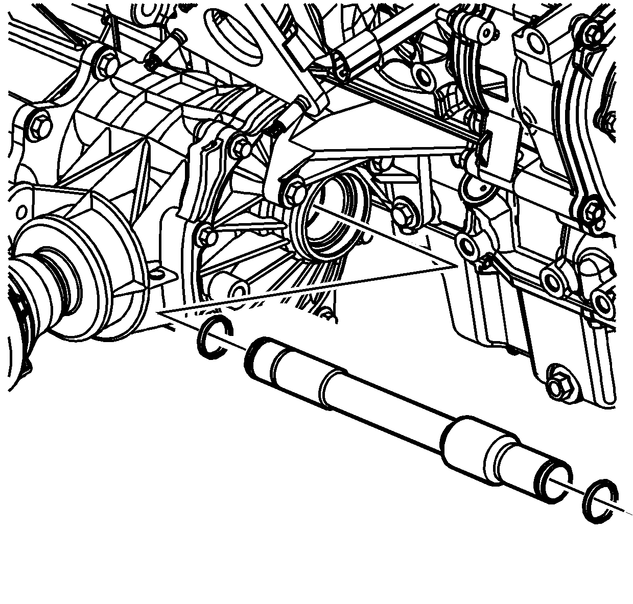

Tighten
Tighten the PTU bolts to 60 N·m (44 lb ft).

Tighten
Tighten the bracket bolts to 60 N·m (44 lb ft).

Tighten
Tighten the bolts to 60 N·m (44 lb ft).

Tighten
Tighten the bolts to 40 N·m (30 lb ft).
Tighten
| • | Tighten the B+ cable to starter nut to 10 N·m (89 lb in). |
| • | Tighten the S terminal nut to 5 N·m (35 lb in). |
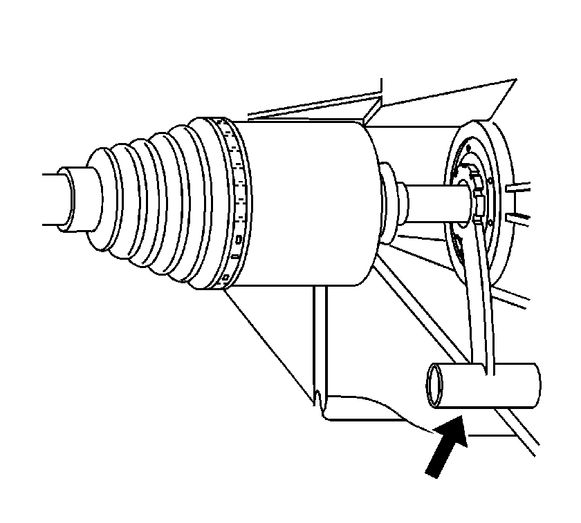
Tighten
Tighten the bolts to 35 N·m (26 lb ft).

Important: Ensure not to damage the seal when inserting the axle into the transmission.

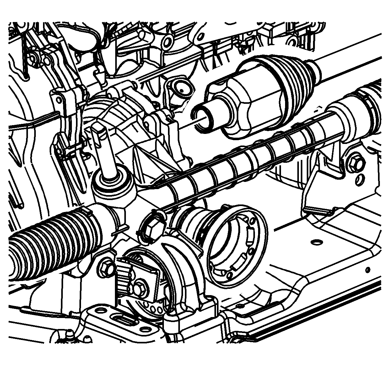
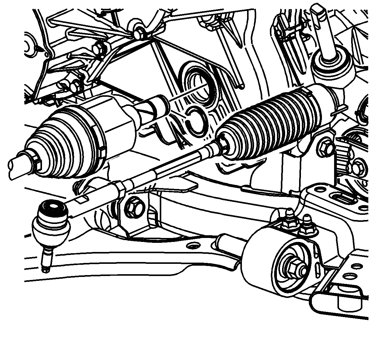
Important: Ensure not to damage the seal when inserting the axle into the transmission.

Tighten
Tighten the bolts to 155 N·m (114 lb ft).

Tighten
Tighten the bolt to 110 N·m (81 lb ft).

Tighten
Tighten the bolts to 50 N·m (37 lb ft).
Tighten
Tighten the
J 44015
to 40 N·m (30 lb ft).

Notice: Do not allow stud to rotate while tightening the nut. Damage may occur to the seal.
Tighten
Tighten the nut to 50 N·m (37 lb ft).

Tighten
Tighten the nut to 10 N·m +150 degrees (89 lb in +150 degrees).

Tighten
Tighten the bolts to 110 N·m (81 lb ft).
Tighten
Tighten the nuts to 65 N·m (48 lb ft).

Tighten
Tighten the drive shaft fasteners to 25 N·m (18 lb ft).
Notice: Avoid spinning the seal in the case bore. Damage to the case bore may result.

Tighten
Tighten the nut to 7 N·m (62 lb in).


Tighten
Tighten the wheel nuts to 125 N·m (92 lb ft).
Tighten
Tighten the nut to 205 N·m (151 lb ft).

Tighten
Tighten the bolts to 50 N·m (37 lb ft).

Tighten
Tighten the bolt to 75 N·m (55 lb ft).


Tighten
Tighten the screws to 16 N·m (12 lb ft).

Tighten
Tighten the screw to 15 N·m (11 lb ft).
Tighten
Tighten the battery terminal bolts to 17 N·m (13 lb ft).
Tighten
Tighten the battery terminal bolts to 17 N·m (13 lb ft).
Tighten
Tighten the screws to 2 N·m (18 lb in).
