Excessive Noise From (One Speed) Engine Cooling Fan at Idle

| Subject: | Excessive Noise From (One Speed) Engine Cooling Fan at Idle (Install Two Speed Cooling Fan Conversion) |
| Models: | Only selected 2002 Saturn VUEs are affected by this bulletin: |
| Vehicles equipped with V6 (L81) engines built up to VIN 2S812653 |
| Vehicles equipped with 4-cylinder (L61) engines and manual transaxles (RPO MG3) built up to VIN 2S812654 |
| IMPORTANT: It will be necessary to perform a visual inspection of the subject vehicle to determine if a two speed fan is already installed. |
Condition
Some customers may comment about an excessively noisy engine cooling fan while vehicle is at idle.
Cause
This condition is caused by some early 2002 model year VUEs having a "High" cooling fan speed setting only. Later vehicles were equipped with a "Low" and "High" speed cooling fan for noise reduction.
Correction
To correct this condition refer to inspection procedure in this bulletin, and if necessary convert single speed cooling fan to a two speed cooling fan.
Inspection Procedure
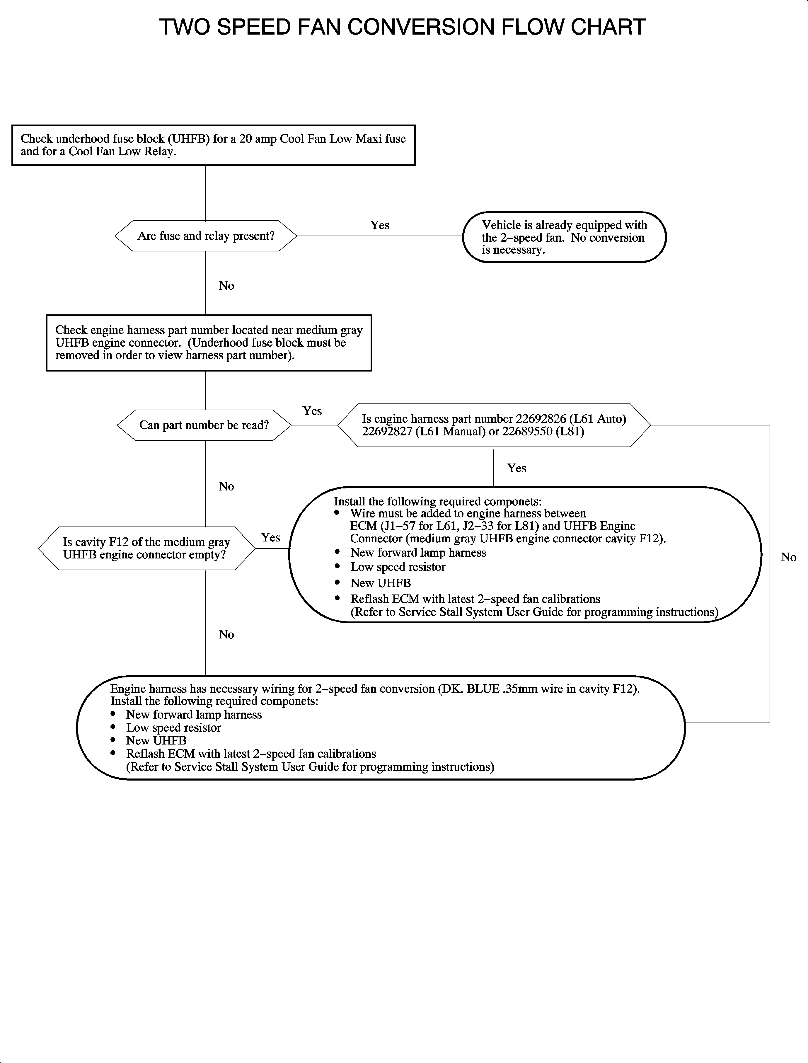
If the VIN on the vehicle is lower than those specified in the "Models Affected" listing on page 1, a visual inspection will be required. Refer to "Two Speed Fan Conversion Flow Chart" on page 3 to determine if the conversion is necessary and if the engine wiring harness requires modification.
If it is determined that the vehicle requires a two speed cooling fan conversion perform the following procedures in the order listed below.
- Engine Wiring Harness Modification (add circuit 473 from ECM to UHFB if required)
- Forward Lamp Harness Installation
- Low Speed Fan Resistor Installation
- New UHFB Installation
- Reprogram ECM With Two Speed Fan Calibration
Two Speed Cooling Fan Conversion Procedure
- Ignition OFF.
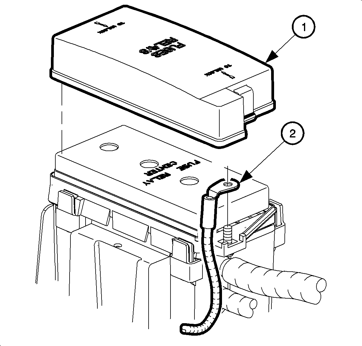
- Remove battery and battery cooling box. Refer to "Battery and Battery Cooling Box Removal" in the Starting and Charging section of the 2002 VUE Engine Service Manual.
- Remove nut at end fuse block and remove both the positive battery cable and the electrical power steering (EPS) cable (2).
- Loosen bolts on the top of the fuse block until the block can be lifted off of the connectors.
- Remove the green 2-way and the white 2-way UHFB power circuit connectors.
- Remove fuse block.
- Pull up on each 68-way connector until it comes out.
- Disconnect ECM harness connector (Connector J1 L61, Connector J2 L81).
- Remove the tape from the rubber gasket and slide gasket off of ECM connector body.
- Remove the back connector cover by releasing the locking tabs.
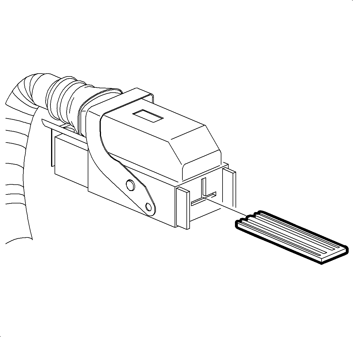
- Remove the terminal position assurance (TPA) piece located in the center of the connector. Use a pocket screwdriver to push out the TPA from the connector.
- Peel back rubber gasket that covers the end of the ECM connector and cut the wiring harness strap that is used to hold the wires together. IMPORTANT: Make sure the locking tabs on the new wire/terminal assembly are slightly bent outward in order to lock the terminal in the connector body.
- Install new terminal and wire from wire assembly kit 22688141 through rubber gasket and into the correct cavity of the connector (Cavity J1-57 for L61, J2-33 for L81).
- Install new wire strap to wiring harness.
- Install TPA.
- Install back connector cover.
- Install rubber gasket onto connector body.
- Remove the back cover of UHFB engine harness connector by releasing the four locking tabs.
- Remove the terminal position assurance (TPA) piece located in the center of the connector. Use a pocket screwdriver to push out the TPA from the connector.
- Install new terminal and wire from lead kit 12167211 into cavity F12 of med. gray UHFB engine connector.
- Install TPA.
- Install the back cover of UHFB engine connector.
- Use salmon colored splice sleeves and service wire (0.8 mm) to connect the installed ECM and UHFB wires following engine harness routing.
- Remove insulation from both ends of cut wire. Recommended strip length is 9.5 mm (3/8 in.). Caution must be used when stripping wire to prevent cutting wire strands. IMPORTANT: With wiring used in Saturn vehicles, it is recommended that crimp and seal splice sleeves (or equivalent) be used.
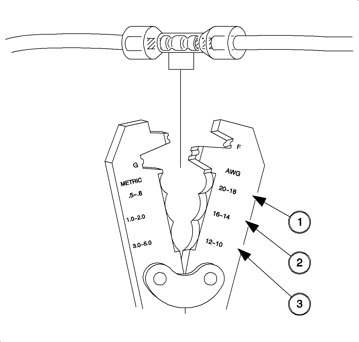
- Using Saturn approved crimp and seal splice sleeve (found in special tools kit J44020), position stripped ends of wires in sleeve until wires hit stop.
- Hand crimp splice sleeve using appropriate crimping tool. Gently tug on wires after crimping to ensure they are secure.
- Apply heat using Ultratorch®(or equivalent) device, heating to 175° C (347° F) until glue flows around edges of sleeve.
- Check repaired wire(s) continuity and verify proper repair.
- Connect ECM connector to ECM.
- Install conduit over new wire.
- Fasten new conduit to engine harness using wiring harness straps.
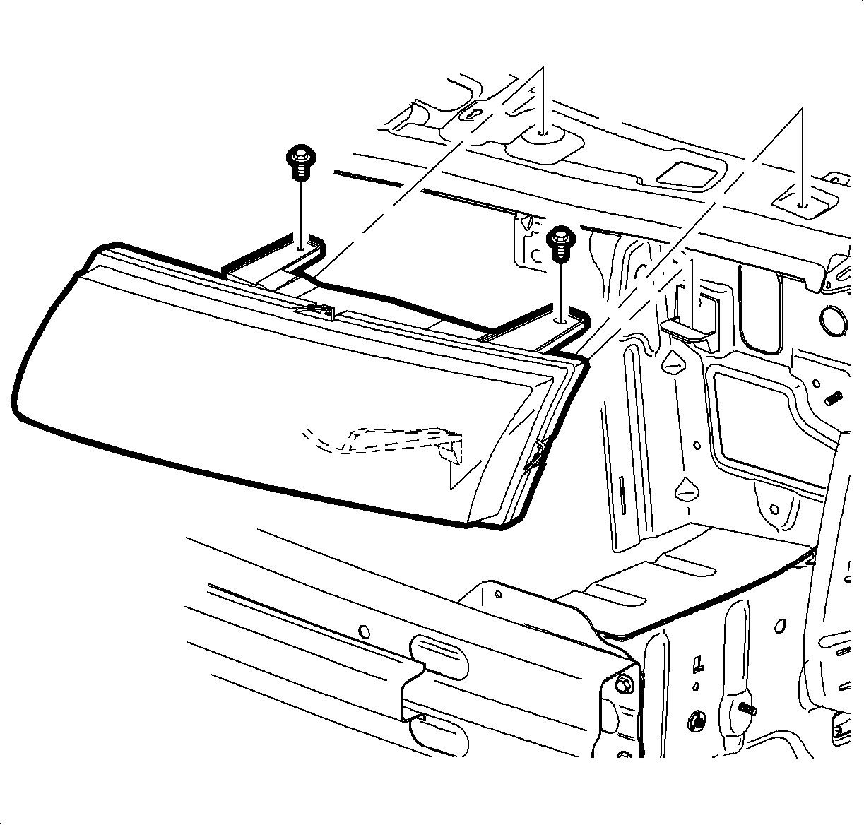
- Remove headlamp and side marker lamps. Refer to "Headlamp Removal" in the Lighting System Section of the 2002 VUE Body Removal and Installation Service Manual.
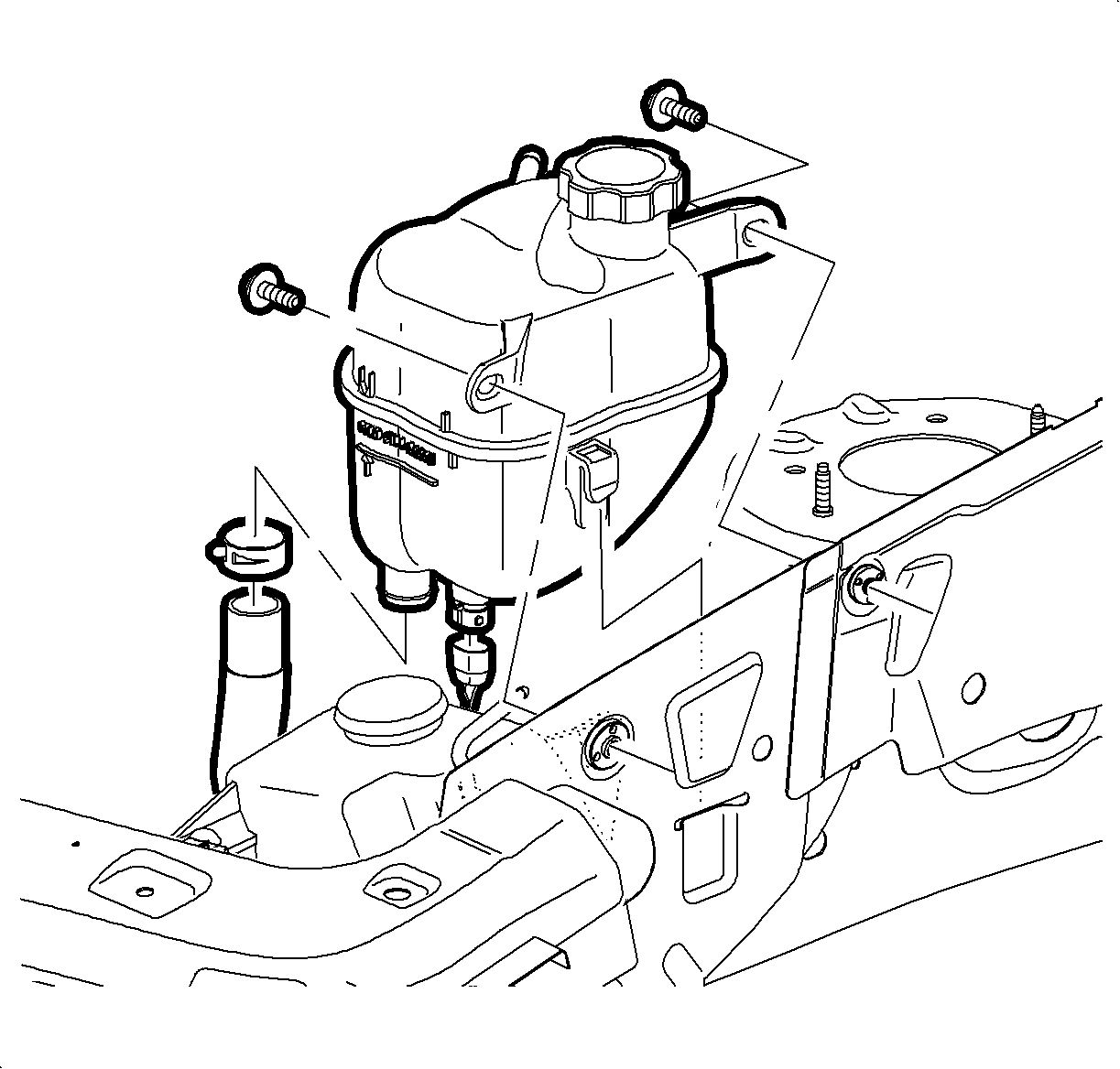
- Remove surge tank to upper motor rail bolts and move tank in order to access forward lamp harness.
- Remove front washer solvent container fastener and move container in order to access forward lamp harness.
- Remove front bush guard (if equipped).
- Remove front fascia. Refer to "Front Fascia Removal" in the Body Front End section of the 2002 VUE Body Removal and Installation Service Manual.
- Disconnect all forward lamp harness connectors, clips and fasteners and remove from vehicle.
- Install forward lamp harness to vehicle and connect all connectors, clips and fasteners.
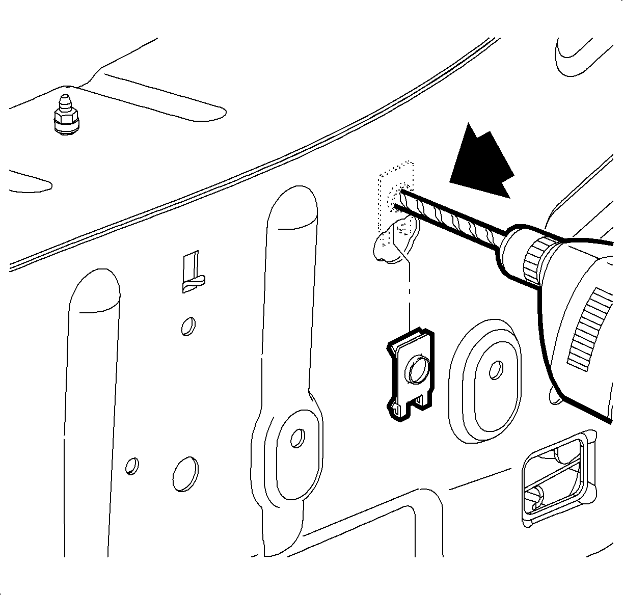
- Locate 13 mm hole in driver's side front lower rail near daytime running lamp (DRL) resistor.
- Use round file to enlarge hole as indicated so that edge clip can be installed. Install edge clip with threads to the rear of the clip.
- Use center punch to mark location of hole to be drilled for resistor retaining bolt.
- Remove edge clip temporarily so that hole can be drilled.
- Drill 7 mm hole in rail above existing 13 mm hole.
- Clean area with a wax and grease removing solvent.
- Apply a corrosion-resistant epoxy primer, such as PPG DP90LF (or equivalent), to all bare metal surfaces.
- Install edge clip and mount resistor with fastener.
- Connect resistor to Forward Lamp Inline Connector (med. gray, 2-way).
- Route resistor wiring below daytime running lamp (DRL) resistor and away from sharp edges.
- Secure resistor connector to daytime running lamp wiring harness clip using a tie strap.
- Install front fender to structure bolts, if necessary.
- Install front fascia. Refer to "Front Fascia Installation" in Body Front End section of the 2002 VUE Body Removal and Installation Service Manual.
- Install bush guard (if equipped).
- Install headlamp and side marker lamps. Refer to "Headlamp Installation" in the Lighting System section of the 2002 VUE Body Removal and Installation Service Manual.
- Install washer solvent container and fastener.
- Reposition coolant surge tank and install upper fasteners.
- Install battery cooling box. Refer to "Battery Cooling Box Installation" in the Starting and Charging section of the 2002 VUE Engine Service Manual.
- Install each 68-way connector into its proper location.
- Push down on each 68-way connector until it is seated into the fuse block case.
- Install green 2-way and white 2-way UHFB power circuit connectors into new fuse block.
- Place new fuse block on the 68-way connectors.
- Tighten bolts on the top of the fuse block.
- Replace both the positive battery cable and the EPS cable at the end of fuse block with nut.
- Replace cover.
- Install battery. Refer to "Battery Installation" in the Starting and Charging section of the 2002 VUE Engine Service Manual.
- Connect positive battery cable to battery.
- Connect negative battery cable to battery.
- Install battery cooling box cover and tighten screws.
- Reprogram radio stations.
- Reflash ECM with the latest 2002 model year two speed fan Calibration. Refer to "ECM Programming" in the Service Programming System section of the Service Stall System (SSS)/Tech 2 User Guide for reprogramming procedures.
Important: Record all pre-set radio stations.
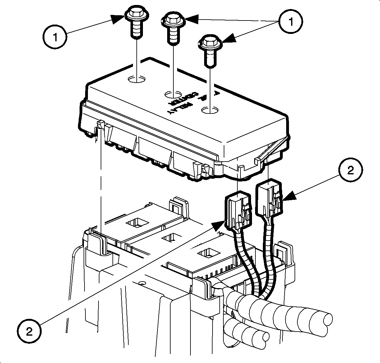
| • | (1) Bolts |
| • | (2) UHFB power circuit connectors |
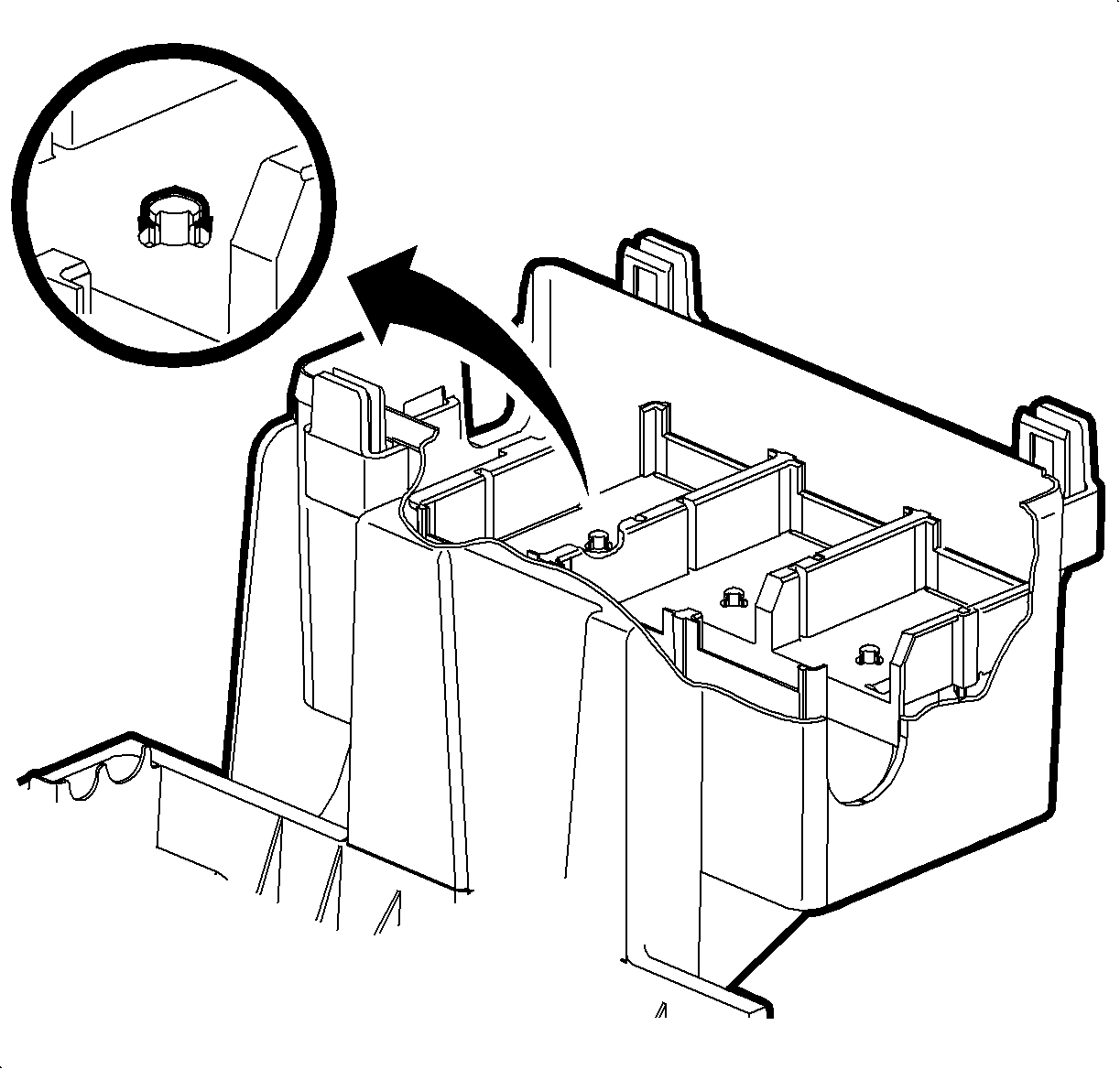
Important: All 3-fuse block 68-way connectors are held in place on the fuse block case by a push pin design.
Important: Steps 7-31 should only be completed if required. Refer to the Two Speed Fan Conversion Chart at the beginning of this bulletin to determine if the engine wiring harness requires modification.

| • | (1) Fuse block case |
| • | (2) Forward Lamp 68-way |
| • | (3) Engine 68-way |
| • | (4) Body 68-way |
17.1 Install tape on rubber gasket in order to secure the gasket to engine harness.
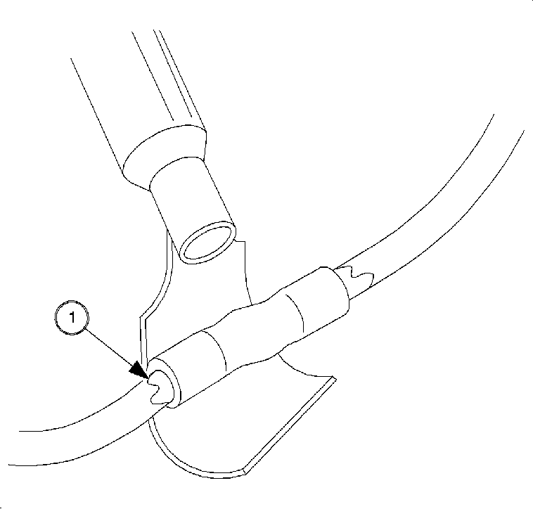
Caution: DO NOT USE A MATCH OR OPEN FLAME TO APPLY HEAT TO SPLICE SLEEVE.
Important: It may be easier to install new forward lamp harness as existing harness is being removed.
Important: It may be necessary to tape back unused fog lamp (BLK 2-way) and/or outside air temp sensor (LT. GRN 2-way) connectors when installing forward lamp harness.
Important: The park/turn lamp socket may not be compatible with the new forward lamp harness. If no locking "click" is heard when connecting park/turn lamp socket to connector, replace existing socket with new socket P/N 22702944.
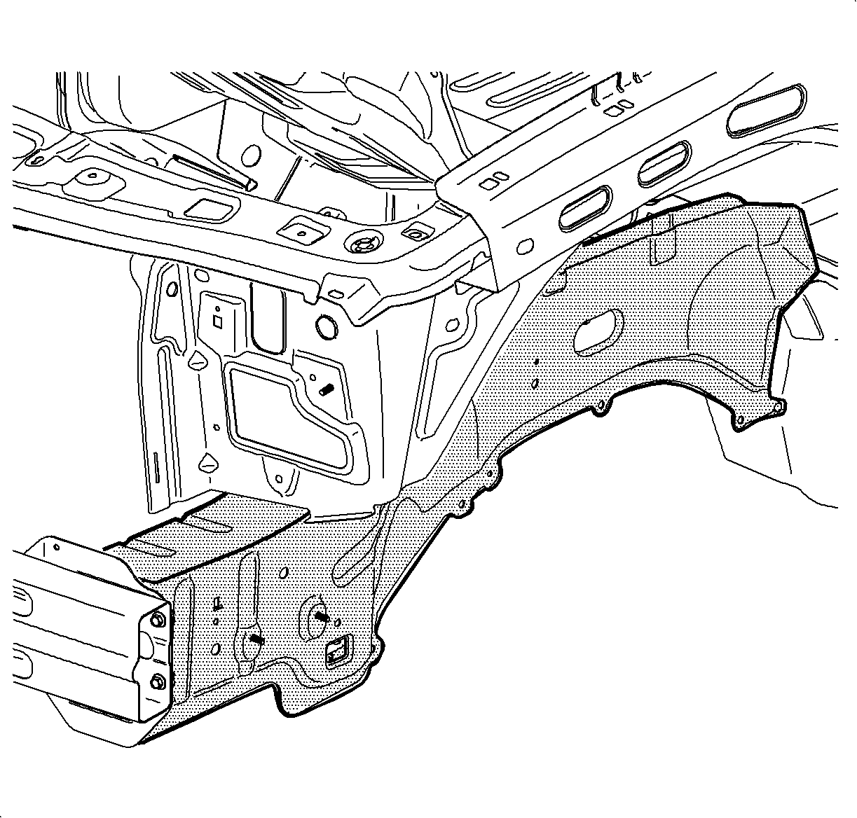
Caution: Resistor gets extremely hot during operation. It must be mounted on front lower outer rail away from plastic body panels near daytime running lamp (DRL) resistor.
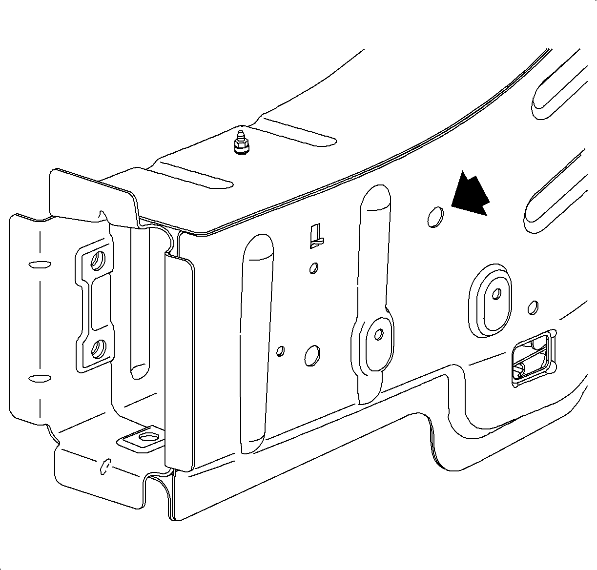
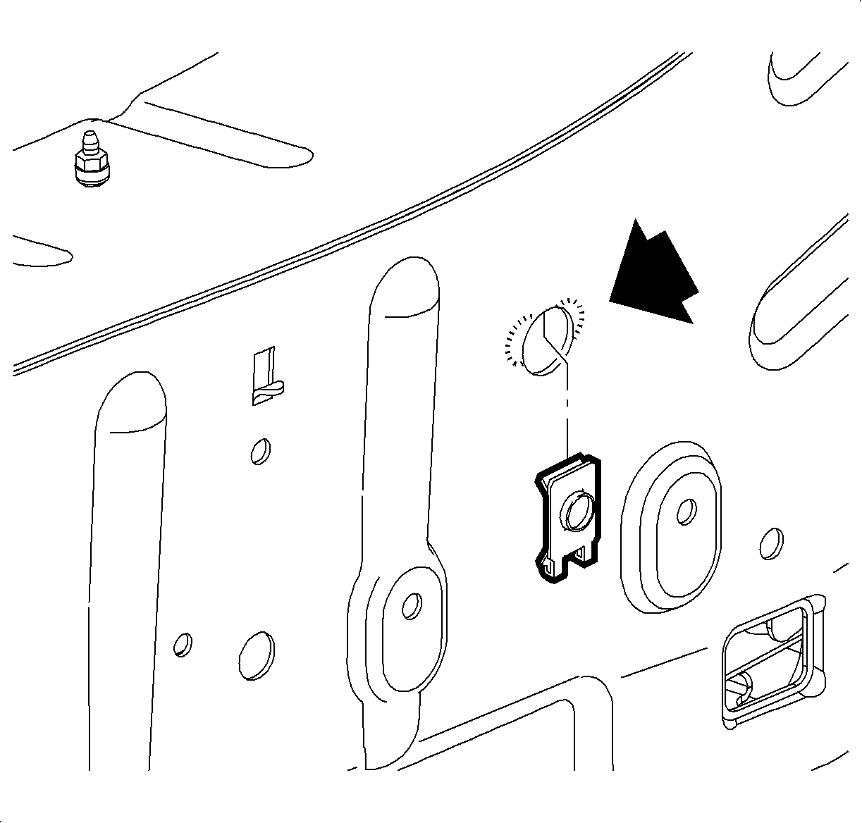
Important: It may be necessary to loosen the front fender fasteners so that fender can be pulled away in order to provide clearance for drill.
Tighten
Tighten the Low Speed Resistor Mounting Screw To 10 N·m (89 in lbs)
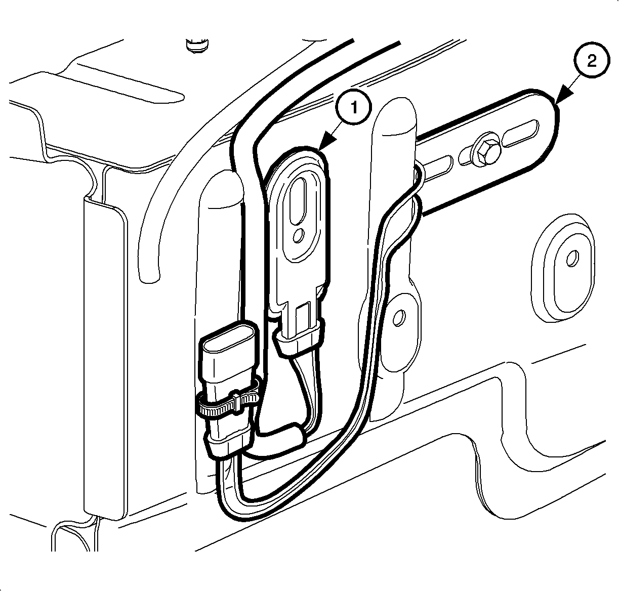
| • | (1) Daytime running lamp (DRL) resistor. |
| • | (2) Low speed cooling fan resistor. |
Tighten
Tighten the Front Fender to Structure Bolts to 9 N·m (80 in lbs)

Tighten
Tighten the Front Washer Solvent Container Fastener to 2.5 N·m (22 in lbs)

Tighten
Tighten the Coolant Surge Tank Fasteners to 6 N·m (53 in lbs)

Important: Do not install negative battery cable at this time.
Important: All 3 fuse block 68-way connectors are held into place to the fuse block case by a push pin design.
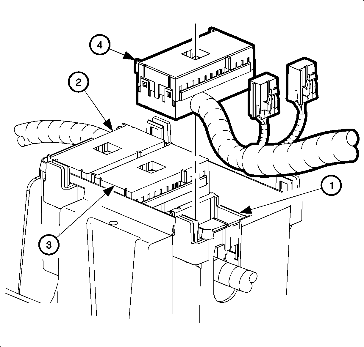
| • | (1) Fuse block case |
| • | (2) Forward Lamp 68-way |
| • | (3) Engine 68-way |
| • | (4) Body 68-way |

Tighten
Tighten theUnderhood Fuse Block To 4 N·m (35 in lbs)
| • | (1) Bolts |
| • | (2) UHFB power circuit connectors. |

Tighten
Tighten the UHFB B+ Terminal Nut To 10 N·m (89 in lbs)
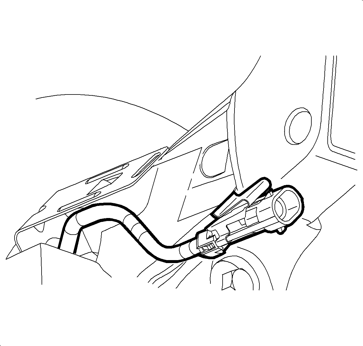
Tighten
Tighten the Battery Terminal Bolts To 17 N·m (13 ft lbs)
Tighten
Tighten the Battery Terminal Bolts To 17 N·m (13 ft lbs)
Tighten
Tighten the Battery Cooling Box Cover Screws To 2 N·m (18 in lbs)
Important: Saturn Service Stall System (SSS), software version 10.5 or greater is required in order to reprogram ECM.
Parts Information
Part Number | Description |
|---|---|
22698605 | UHFB (L81) |
22698603 | UHFB (L61) |
22699084 | Forward Lamp Harness |
22698615 | Low Speed Fan Resistor |
11517510 | Mounting Bolt |
22698616 | Washer |
21108895 | J-Clip |
12116140 | Wire (.8 mm) |
22688141 | Wire Assembly Kit (ECM Terminals) |
12167211 | Wire Assembly Kit (UHFB Terminals) |
21023494 | Wire Conduit |
21020792 | Wiring Harness Strap (10 required) |
22702944 | Park/Turn Lamp Socket (2 required if necessary) |
Warranty Information
To receive credit for this repair during the warranty coverage period, submit a claim through the Saturn Dealer System for J3702 (Convert Single speed Cooling Fan to Two-Speed).
