Hiss/Chirp Noise in Park or Neutral

| Subject: | Hiss/Chirp Noise in Park or Neutral (Replace Control Valve Body Spacer Plate) - Due to an incorrect part number, this bulletin has been revised and supersedes bulletin 02-T-66, which should be discarded. |
| Models: | 2002 VUE Vehicles with 2.2L (L4) Engine and VT25-E Transaxle (M75/M16) |
Condition
Some customers may comment about a hissing or chirping noise. This condition occurs at normal operating temperature when the transmission range is in Park or Neutral and the engine RPM is at idle. The noise is similar to an alternator belt chirp or a vacuum leak.
Cause
The noise is caused by transmission fluid passing through a sharp-edged orifice (#19) in the control valve body spacer (with gasket) plate assembly. When the transmission range is in Park or Neutral, line pressure fluctuates in order to clean the solenoids. This line pressure fluctuation contributes to the noise condition.
Correction
Replace the control valve body spacer (with gasket) plate assembly with a newer design which incorporates a chamfered #19 orifice.
Removal Procedure
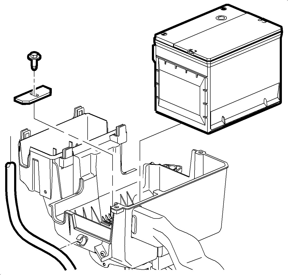
Caution: Do not tip battery over 45° angle or acid could spill.
Important: Record all pre-set radio stations.
- Remove battery.
- Remove battery cooling box. Refer to "Battery Cooling Box" removal procedure in the General Information section of the 2002-2003 Saturn VUE Transaxle Service Manual.
- Remove battery tray bracket.
- Disconnect transaxle electrical connector.
- Remove the 17 bolts from the control valve body cover.
- Remove the control valve body cover.
- Remove the control valve body cover gasket (68). Discard the gasket (68).
- Slide the gray locking clip in order to unlock the connector for the input and output speed sensor assembly.
- Press the connector tab and remove the connector for the input and output speed sensor assembly from the control valve body assembly.
- Remove the bolt and manual shift detent assembly from the control valve body assembly.
- Disconnect the manual valve link assembly from the manual valve.
- Remove the three silver bolts from the control valve body assembly.
- Remove the 15 black bolts from the control valve body assembly.
- Remove the control valve body assembly from the transmission case assembly.
- Remove the spacer plate assembly (73). Discard the spacer plate assembly (73).
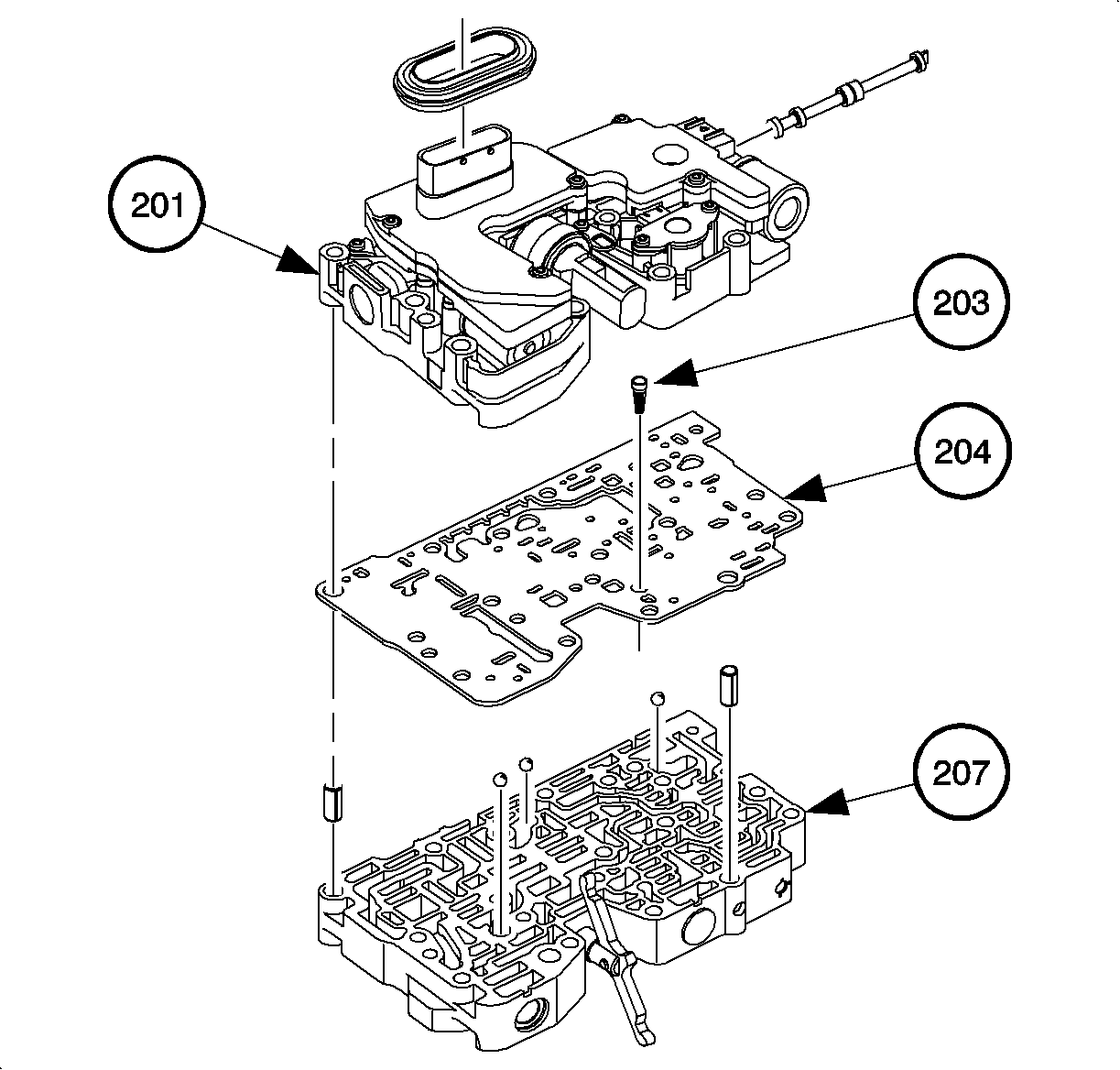
- Carefully separate the control solenoid valve assembly (201) from the control valve body assembly (207).
- Remove the current spacer assembly (204). Discard the spacer plate assembly (204), including the pressure screen assembly (203).
| • | a. Remove battery cover. |
| • | b. Disconnect negative battery cable. |
| • | c. Disconnect positive battery cable. |
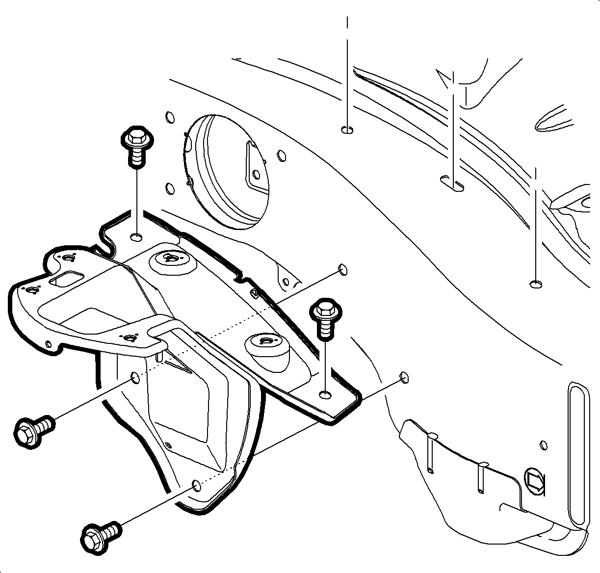
a. Loosen battery tray bracket screws and remove bracket.
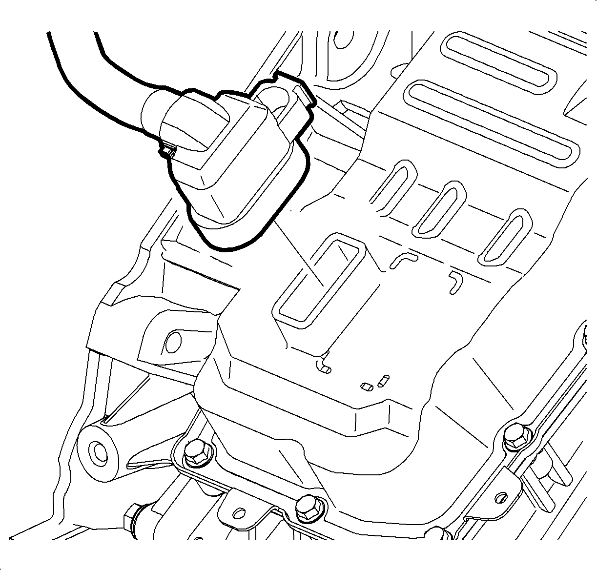
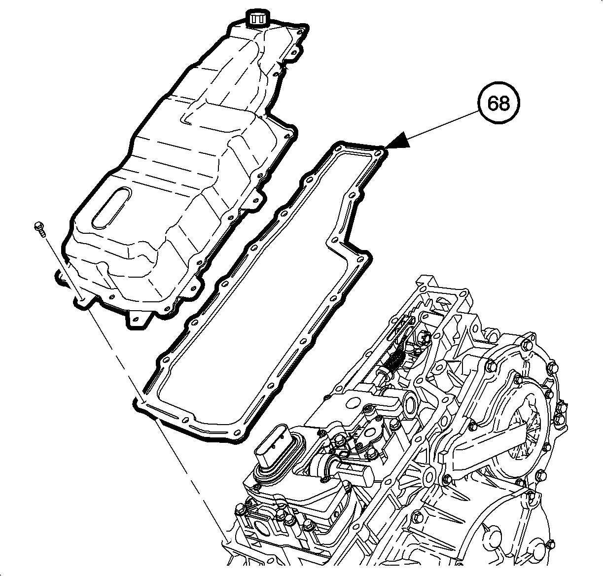
Notice: Use extreme care when performing this procedure in order to prevent dirt or sediment from entering the transmission.
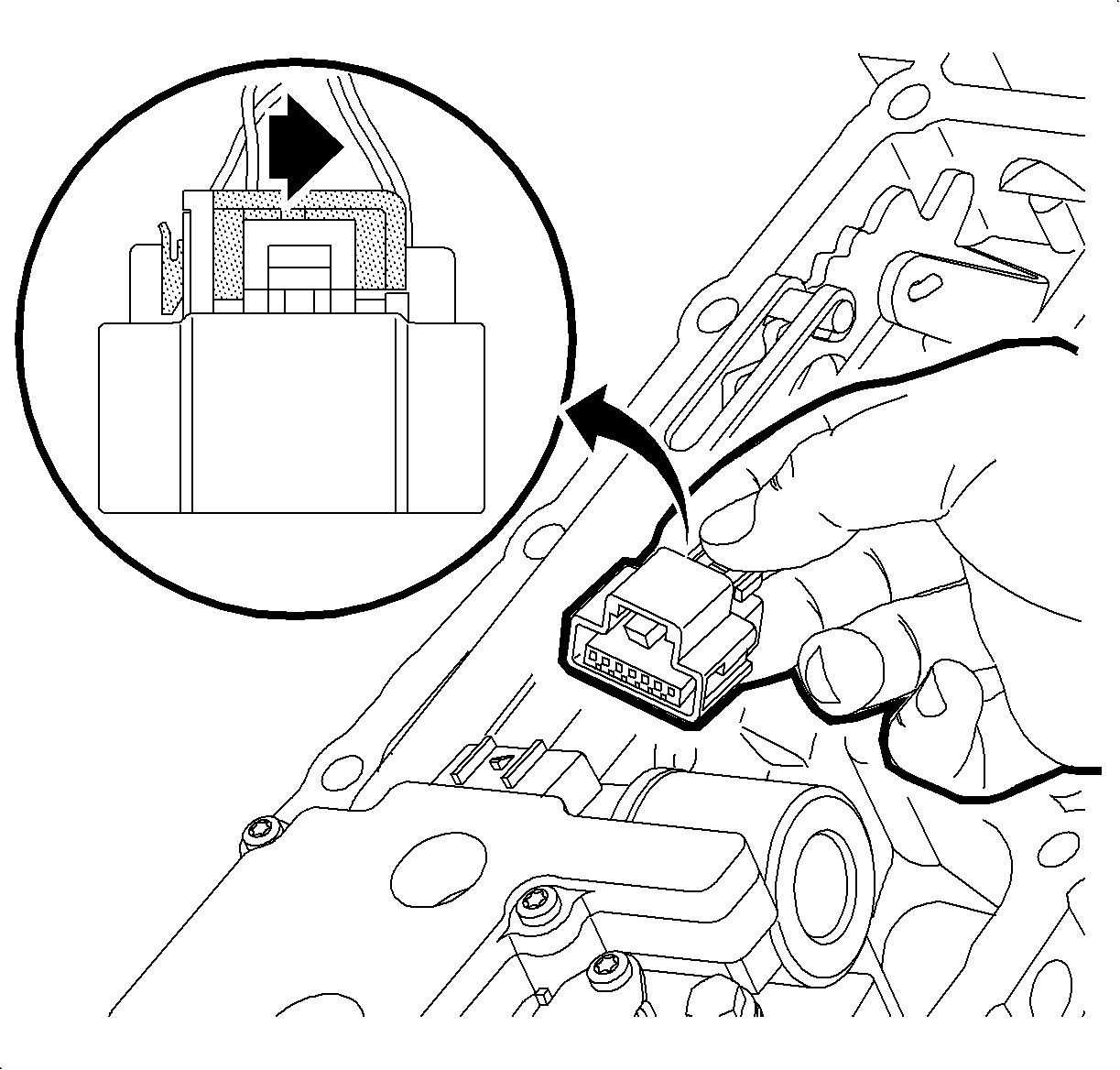
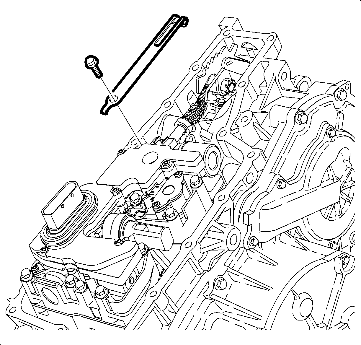
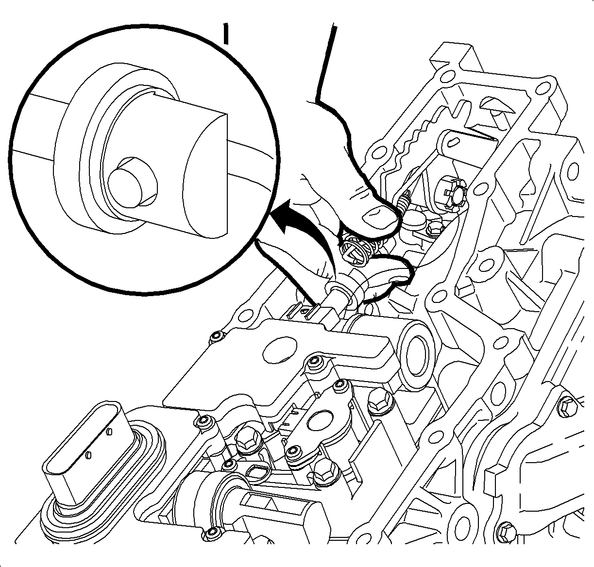
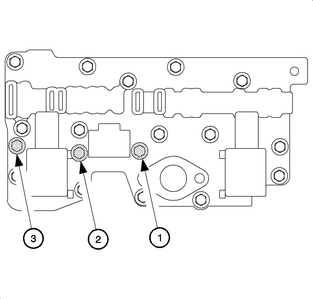
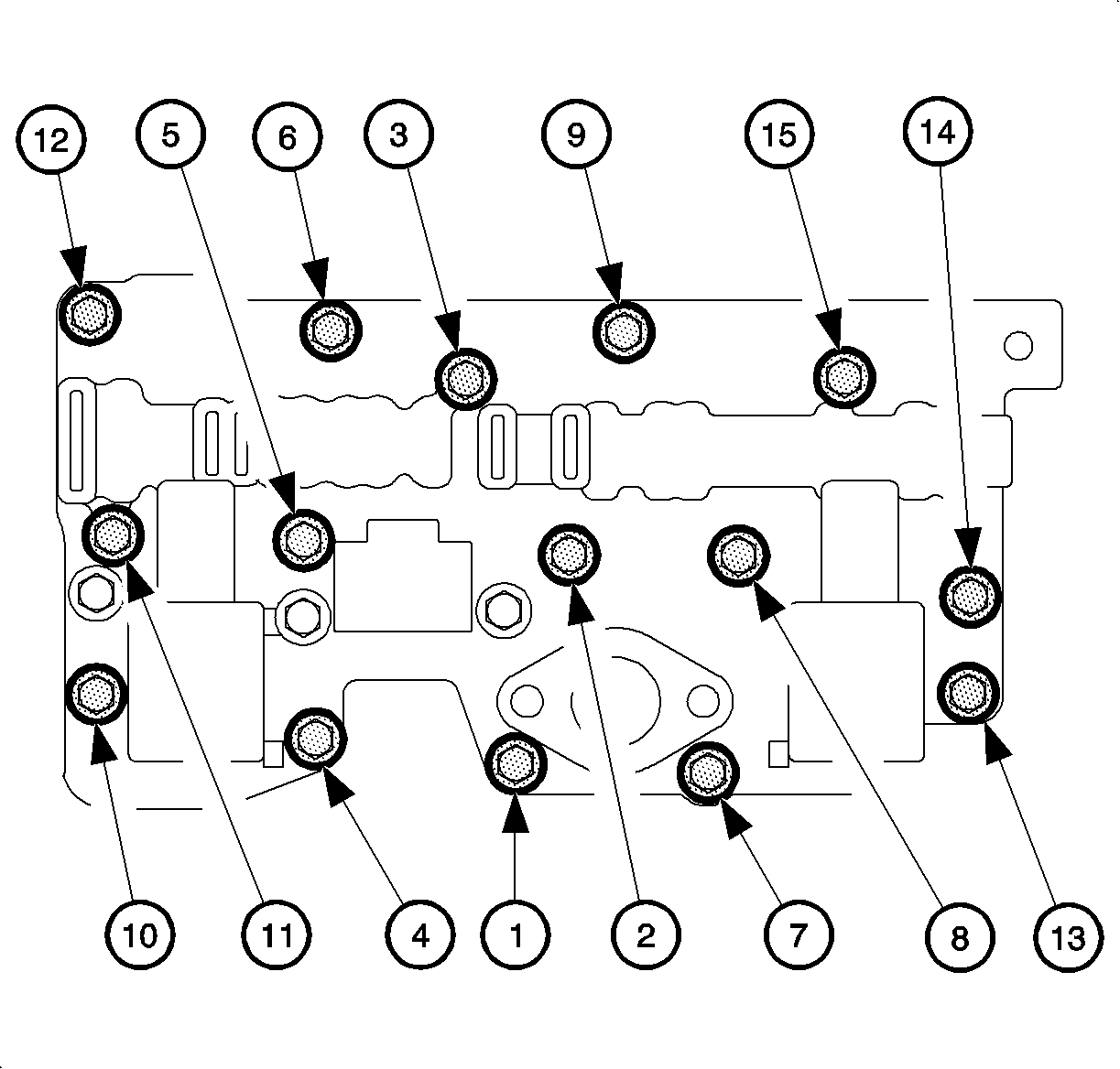
Important: Use care when removing the control valve body assembly. The control solenoid valve assembly and the control valve body assembly may separate.
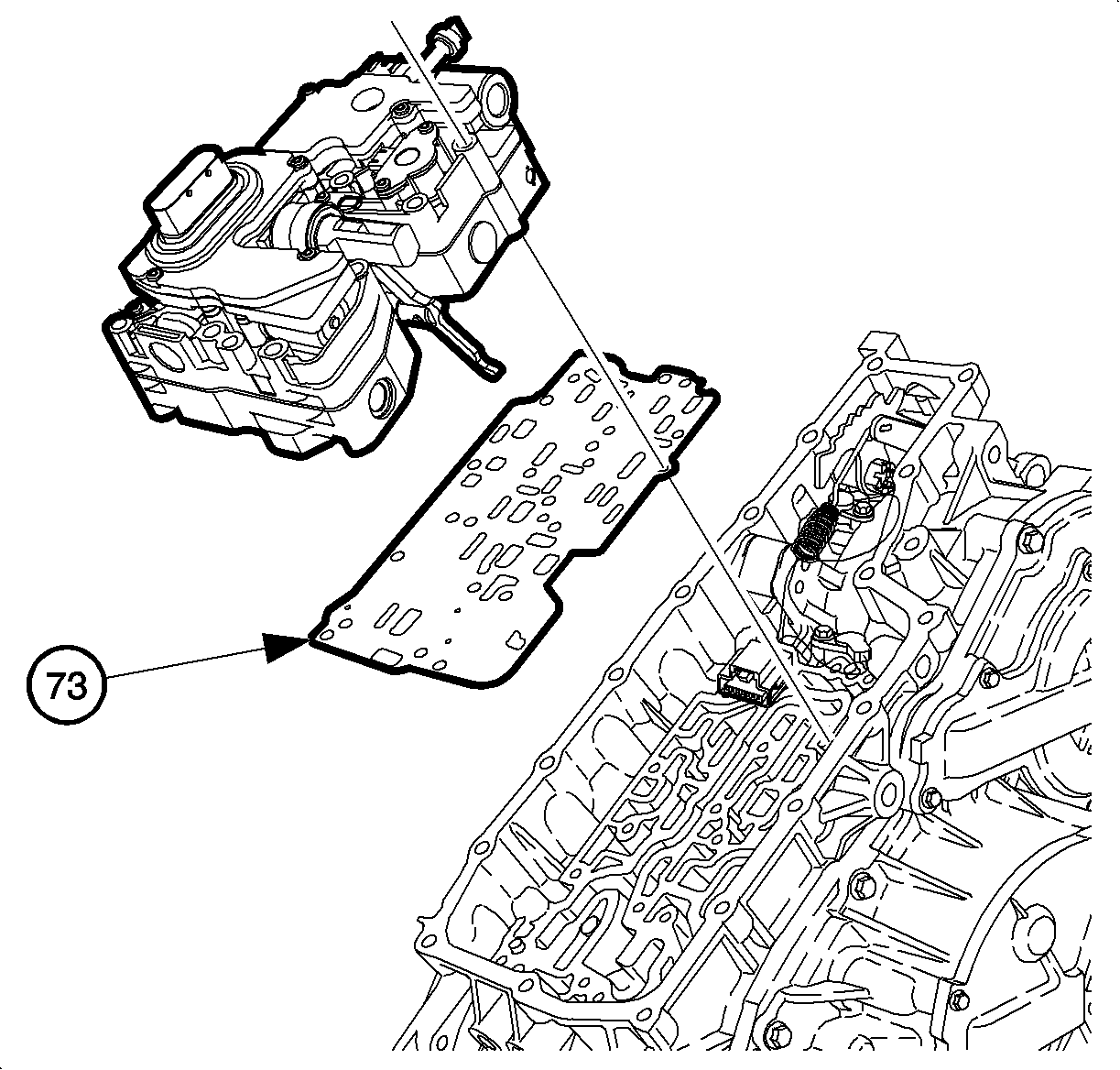
Installation Procedure
- Verify the chamfer on orifice #19 (control valve body side).
- Install a new pressure screen assembly (203) (P/N 08651658) on a new spacer plate assembly (204).
- Install the new spacer plate assembly (204) (P/N 24221859) on the control valve body assembly (207).
- Install the control solenoid valve assembly (201) on the control valve body assembly (207).
- Install a new spacer plate assembly (73) (P/N 24221858) on the transmission case assembly.
- Install the control valve body assembly on the transmission case assembly.
- Secure the control valve body assembly to the transmission case assembly with the 15 black bolts.
- Tighten the 15 black bolts in three separate steps in the sequence shown.
- Secure the control valve body assembly to the transmission case assembly with the three silver bolts.
- Tighten the three silver bolts in the sequence shown.
- Connect the manual valve link assembly to the manual valve.
- Install the manual shaft detent assembly and bolt on the control valve body assembly.
- Install the connector for the input and output speed sensor assembly to the control valve body assembly.
- Slide the gray locking clip in order to lock the connector for the input and output speed sensor assembly.
- Install a new control valve body cover gasket (68) p/n 24220201 on the transmission case assembly.
- Install the control valve body cover and 17 bolts on the transmission case assembly.
- Connect transaxle electrical connector.
- Tighten the 17 bolts in the sequence shown.
- Install battery tray bracket.
- Install battery cooling box. Refer to "Battery Cooling Box" installation procedure in the General Information section of the 2002-2003 Saturn VUE Transaxle Service Manual.
- Install battery.
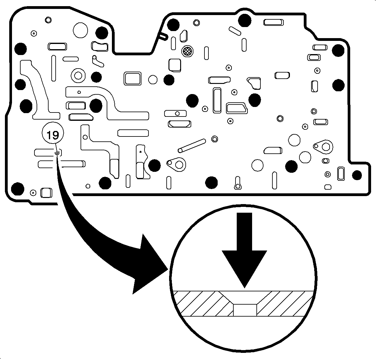
Important: The new, updated spacer plate assembly (204) contains a slight chamfer on the control valve body side of orifice #19.


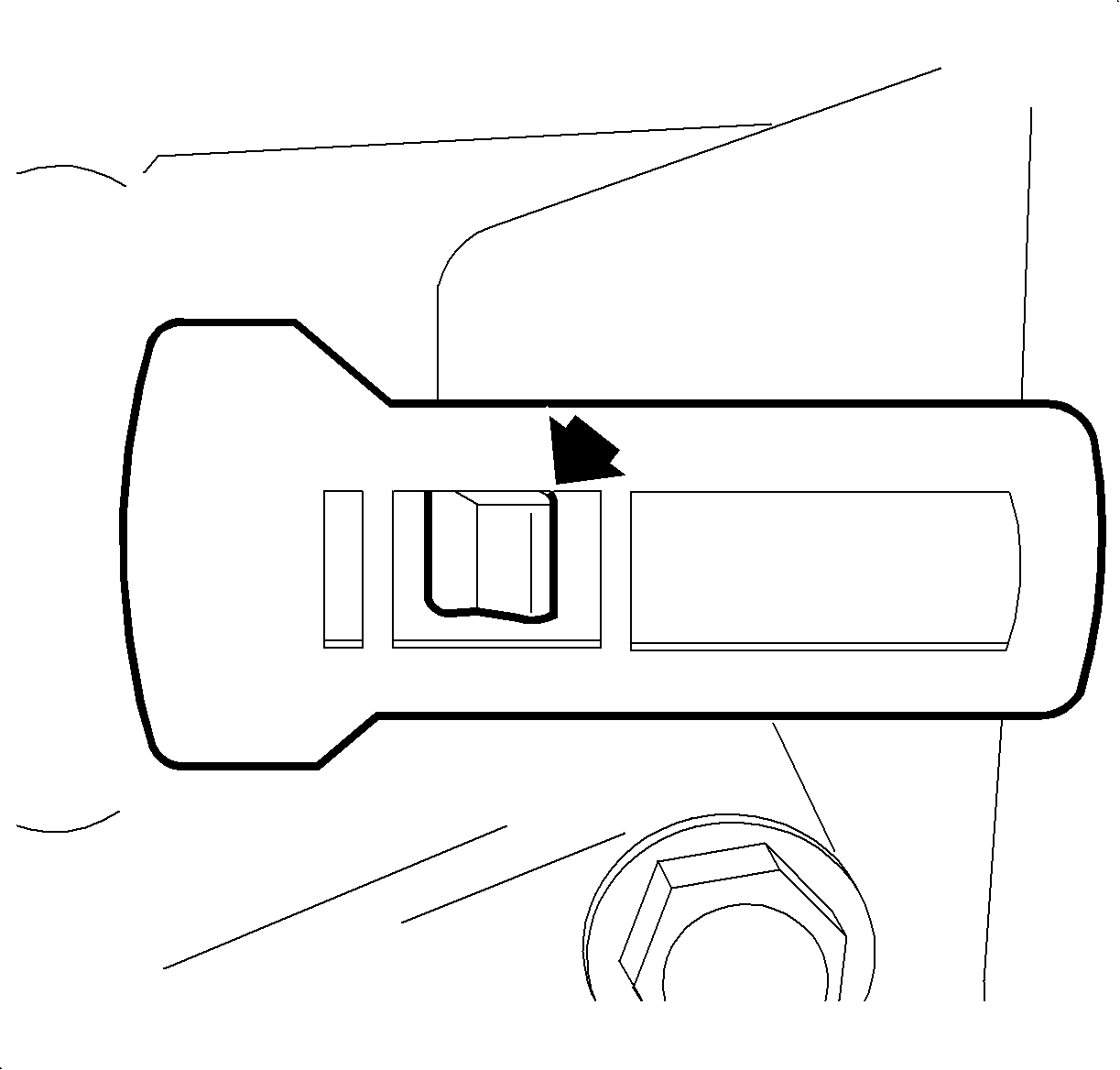
Important: Be certain to note the orientation of the ratio control lever assembly to the ratio control motor before securing the control valve body to the transmission case assembly. The ratio control lever must be properly installed into the off-white guide of the ratio control motor assembly for proper operation.

Tighten
First Step 5 N·m (44 lb in)
Tighten
Second Step 10 N·m (89 lb in)
Tighten
Third Step 14 N·m (10 lb ft)
Tighten
Control Valve Body Assembly Bolts 8 N·m (71 lb in)
Important: Note the orientation of the manual valve before connecting the manual valve link assembly. The link assembly should insert into the flat surface of the valve.
Tighten
Bolt 8 N·m (11 lb ft)
Tighten
Bolt 8 N·m (11 lb ft)
19.1 Position battery tray bracket and tighten screws.
Tighten
Battery Tray Bracket Screws 16 N·m (12 lb ft)
| 21.1. | Insert battery and tighten battery hold-down screw. |
Tighten
Battery Hold-Down Screw 15 N·m (121 lb ft)
| 21.2. | Connect positive battery cable to battery. |
Tighten
Battery Terminal Bolts 17 N·m (11 lb ft)
| 21.3. | Connect negative battery cable to battery. |
Tighten
Battery Terminal Bolts 17 N·m (11 lb ft)
| 21.4. | Install battery cooling box cover and tighten screws. |
Tighten
Battery Cooling Box Cover Screws 2 N·m (18 lb in)
| 21.5. | Reprogram radio stations. |
Parts Information
Part Number | Description |
|---|---|
24221859 | Control Valve Body Spacer (w/Gasket) Plate Assembly |
08651658 | Trans Fluid Pump Pressure Screen Assembly |
24221858 | Control Valve Body Spacer (w/Gasket) Plate Assembly |
24220201 | Control Valve Body Cover Gasket |
Warranty Information
To receive credit for this repair during the warranty coverage period, submit a claim through the Saturn Dealer System for K6563 (Valve Body Assembly, Upper Control - R & R or Replace).
