Elimination of Auxiliary Water Pump and Instructions to Install 2nd Design Heater Outlet Hoses in Place of the 1st Design Water Pump and Heater Outlet Hoses

| Subject: | Service Information Regarding Elimination of Auxiliary Water Pump and Instructions to Install 2nd Design Heater Outlet Hoses in Place of the 1st Design Water Pump and Heater Outlet Hoses |
| Models: | 2002 Saturn VUE vehicles equipped with V6 (L81) engines |
Purpose
The auxiliary water pump is not needed for vehicles equipped with V-6 engines. Therefore, any time a heater outlet hose and/or an auxiliary water pump needs to be replaced, the complete heater outlet circuit should be removed and replaced with 2nd design heater outlet hoses. Refer to the service procedure in this bulletin to update the heater outlet hose circuit.
Service Procedure
- Disconnect negative battery cable.
- Remove coolant cap from surge tank.
- Place coolant container under radiator drain valve located at the bottom of the right radiator end tank.
- Using flat bladed screwdriver, open drain valve and drain coolant.
- Loosen clamp at air cleaner assembly and throttle body assembly.
- Remove attachment bolts from outlet resonator/duct assembly from support bracket.
- Remove outlet resonator/duct assembly.
- Remove battery cooling box/UHFB assembly. Refer to "Battery Cooling Box" removal procedure in the Starting and Charging section of the 2002-2003 VUE Engine Service Manual.
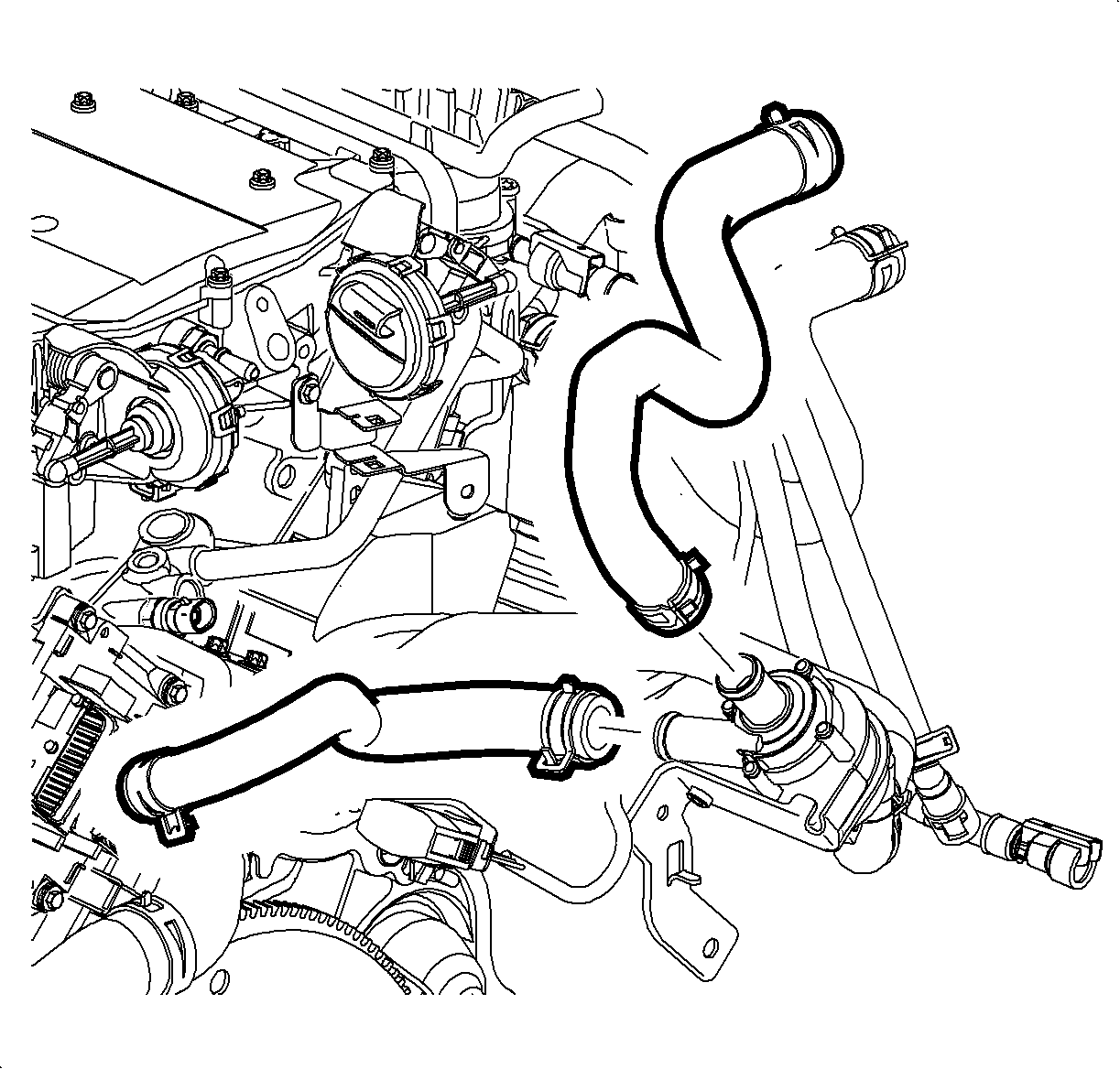
- Remove heater outlet hose clamp and hose from heater core outlet pipe.
- Remove auxiliary coolant pump hose clamp and hose from engine port.
- Raise vehicle.
- Disconnect auxiliary coolant pump from engine harness connector.
- Remove pump bracket to transaxle nut.
- Remove auxiliary coolant pump with hoses and discard.
- Lower vehicle.
- Disconnect auxiliary coolant pump harness from clips for better access.
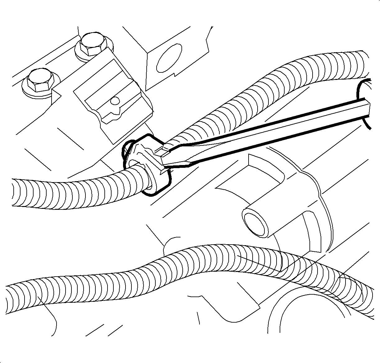
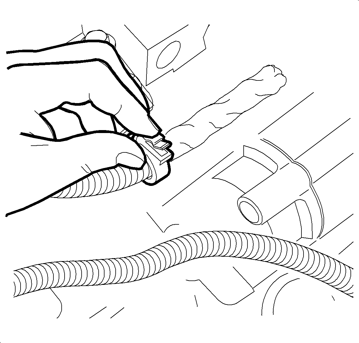
- Cut connector for auxiliary coolant pump from engine harness at the connector.
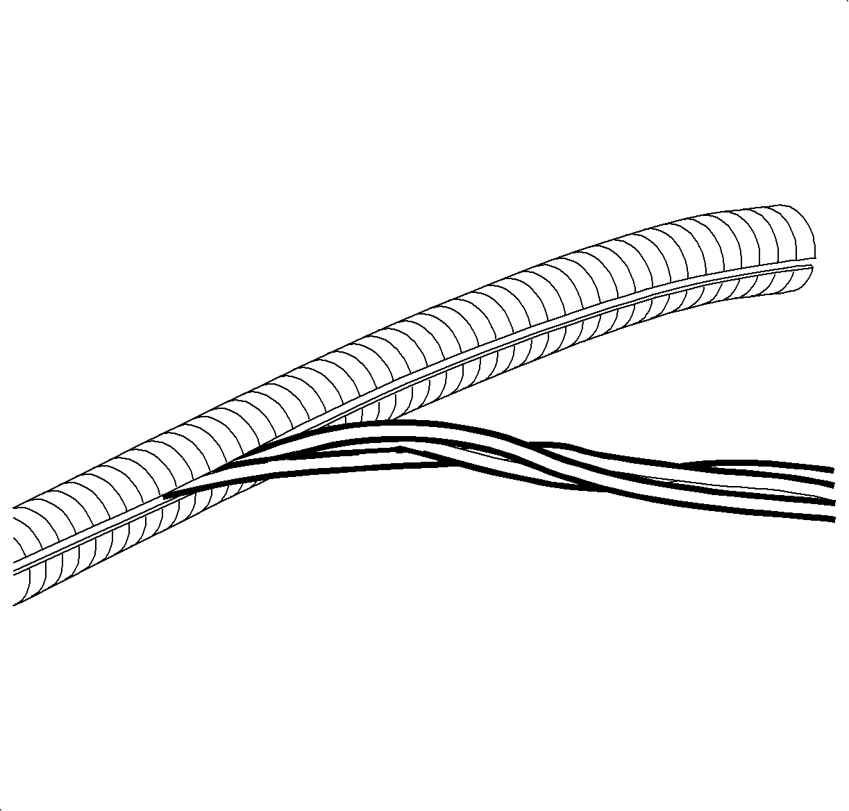
- Remove a short length of the two wires from conduit.
- Cut one wire 51 mm (2 in.) shorter than the other, with the longest being 25.5 mm (1 in.) shorter than the conduit.
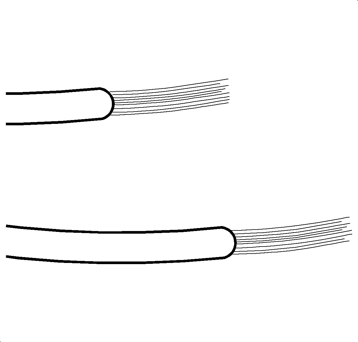
- Remove insulation from end of cut wires. Recommended strip length is 9.5 mm (3/8 in.).
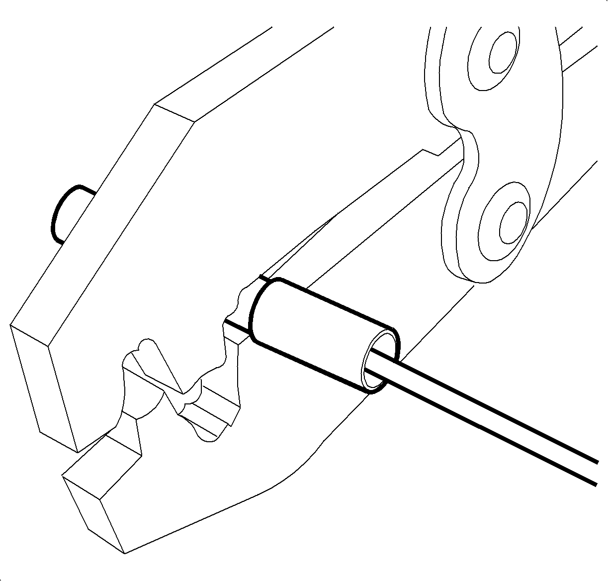
- Install splice sleeve P/N 12089189 by positioning stripped end into sleeve until wire hits stop in center of the splice sleeve
- Hand crimp sleeve using the approved crimping tool (found in terminal repair kit J-44020). Gently tug on wires to make sure they are secure before applying heat to them.
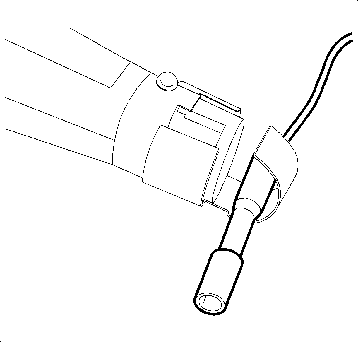
- Apply heat using the heat gun or some other device, heat to 175°C (347°F) until glue flows around edges of sleeve.
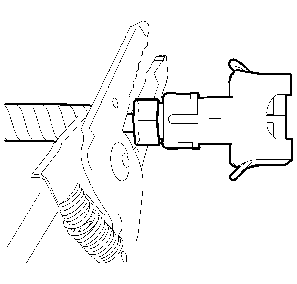
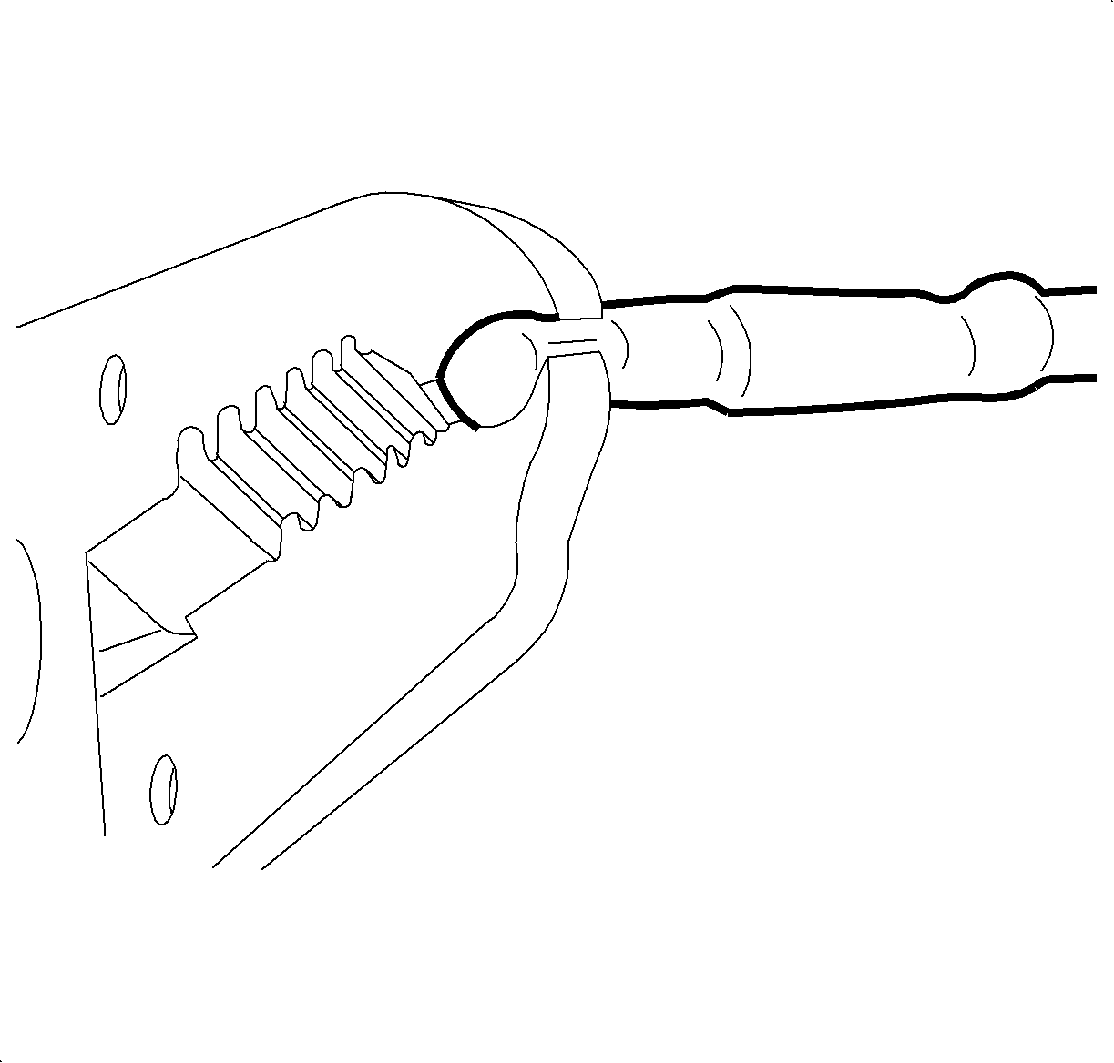
- While hot use a pair of pliers and pinch open end of sleeve together holding for about 10 seconds.
- Repeat steps 21 - 25 on second wire.
- Tape wires together and install into conduit.
- Wrap end of conduit with electrical tape.
- Install conduit into attachment clips.
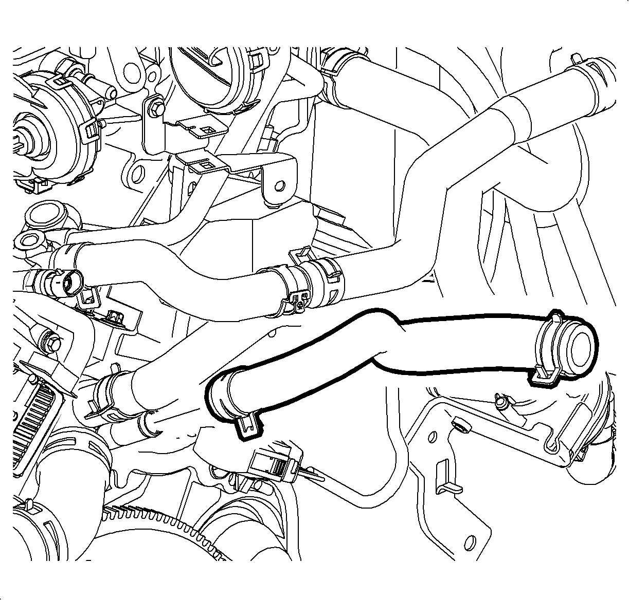
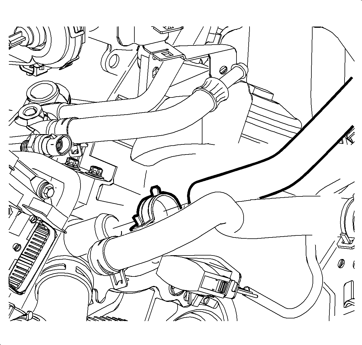
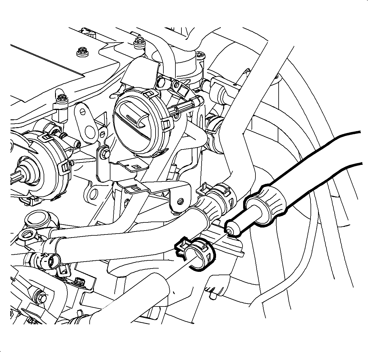
- Install 2nd design front heater outlet hose to engine port. Position clamp P/N 22704429 at 3 o'clock position.
- Install 2nd design rear heater outlet hose to heater core outlet pipe. Position clamp P/N 11516226 at 9 o'clock position.
- Install front heater outlet hose to rear heater outlet hose. Position clamp P/N 11516223 at 2 o'clock position.
- Install battery cooling box/UHFB assembly. Refer to "Battery Cooling Box" installation procedure in the Starting and Charging section of the 2002-2003 VUE Engine Service Manual.
- Install outlet resonator/duct assembly into position.
- Tighten clamp at throttle body assembly.
- Position outlet resonator/duct assembly to support bracket and install bolts.
- Tighten clamp at air cleaner assembly.
- Connect negative battery cable.
- Slowly add a mixture of 50/50 DEX-COOL® antifreeze and clean water to coolant surge tank until the level reaches the top of the "Cold fill Range" (surge tank seam).Cooling system volume, including heater core: 6-Cyl - 8.0 L (8.45 qt.)
- Run engine and cycle the vehicle from idle to 3000 rpms in 30 second intervals until the engine cooling fan comes on (engine cooling fan turns on at approximately 216°F [102°C]).
- Return the engine to idle, idle for 30 seconds then turn engine off.
- Add coolant to the surge tank until the level reaches surge tank vent port.
- Install coolant surge tank cap.
Caution: DO NOT ATTEMPT TO OPEN COOLANT CAP WHILE COOLING SYSTEM IS UNDER PRESSURE.
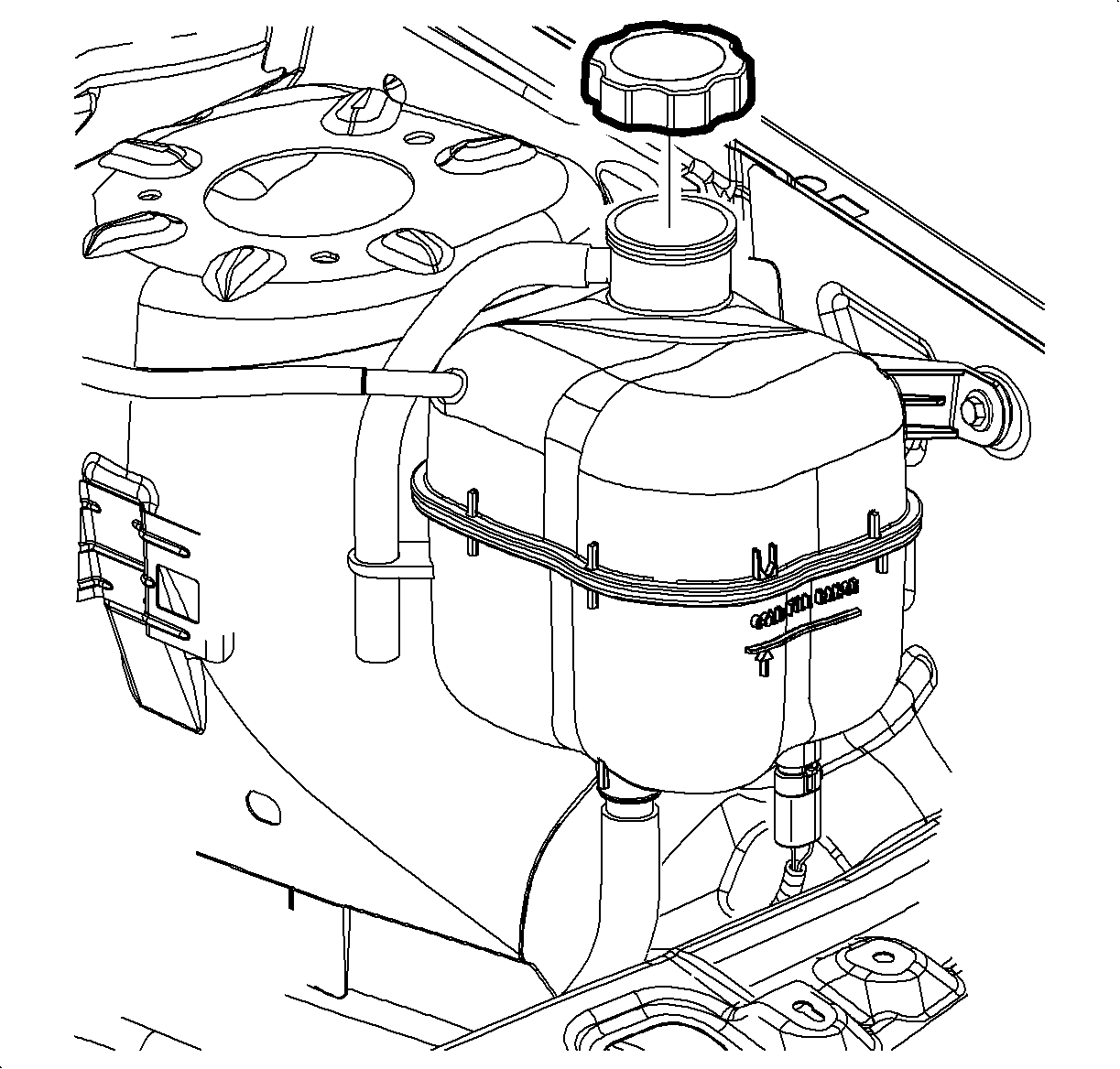
Important: A 7.5 liter (8 qt.) coolant container will be needed.
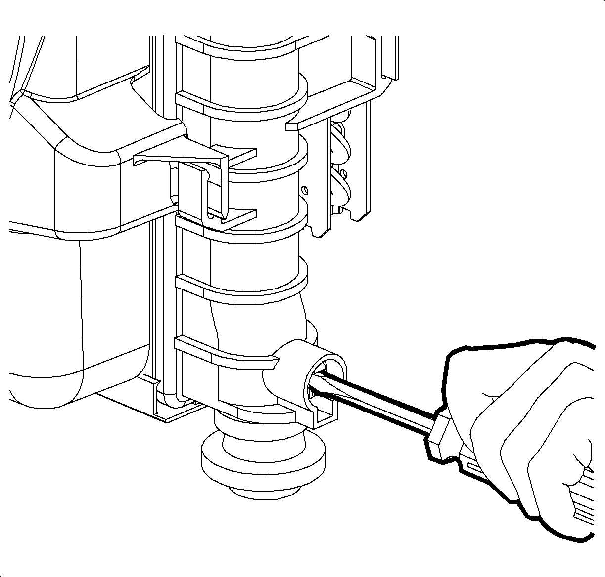
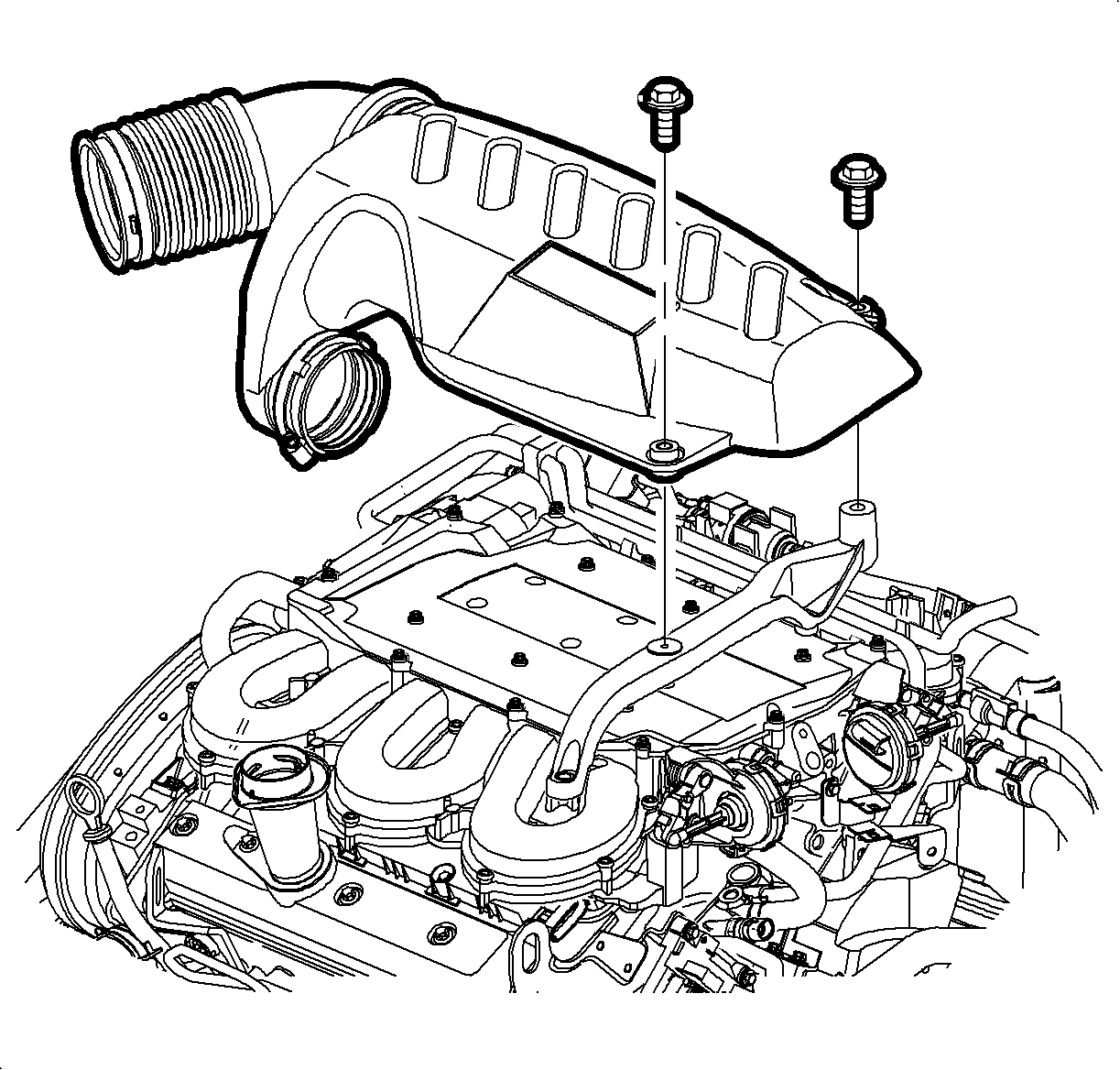
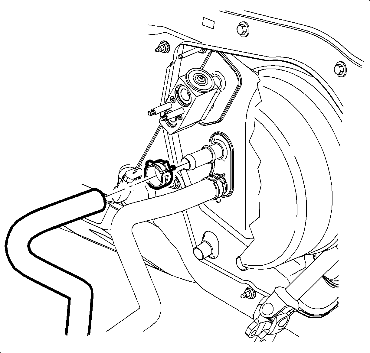
Caution: MAKE SURE VEHICLE IS PROPERLY SUPPORTED AND SQUARELY POSITIONED ON THE HOIST. TO HELP AVOID PERSONAL INJURY WHEN A VEHICLE IS ON A HOIST, PROVIDE ADDITIONAL SUPPORT FOR THE VEHICLE ON THE OPPOSITE END FROM WHICH COMPONENTS ARE BEING REMOVED.
WIRE SIZE: .35 .5 .8
GAGE: 22 20 18
Part Number: 217127* - Salmon -
* Can be ordered through Kent Moore, SPX by calling 1-800-345-2233.
Also available in the Saturn Special Tool Catalog found with J44020 Terminal Repair Kit.
Caution: DO NOT USE MATCH OR OPEN FLAME TO APPLY HEAT TO SEAL


Tighten
Tighten the outlet resonator/duct assembly-to-support bracket bolts - 6-cylinder
engine to 10 N·m (89 lb in).
Tighten
Tighten the battery terminal bolt to 17 N·m (13 lb ft).
Notice: All entrapped air must be purged from the powertrain cooling system before final coolant level can be determined. Proper coolant level is critical to avoid engine damage.
Important: Vehicle must be level when filling cooling system.
Important: Level in the surge tank will return into the cold fill range once the vehicle cools.

Parts Requirements
Part Number | Description | Qty |
|---|---|---|
22704428 | 2nd Design HTR Hose Outlet FRT | 1 |
22704432 | 2nd Design HTR Hose Outlet RR | 1 |
11516226 | Clamp Rear Heater Outlet | 1 |
11516223 | Clamp Front Heater Outlet | 1 |
22704429 | Clamp Engine Outlet | 1 |
217127 * | Splice Sleeve - Salmon | 2 |
* Can be ordered through Kent Moore, SPX by calling 1-800-345-2233. | ||
Also available in the Saturn Special Tool Catalog found with J44020 Terminal Repair Kit. | ||
Claim Information
To receive credit for this repair under the warranty coverage period, submit a claim through the Saturn Dealer System for D2775 (Hoses, Heater, Outlet-Replace. An "add time" condition is provided to replace the auxiliary water pump with the new hoses).
