HVAC Module Condensation Leak Into Driver and Passenger Side Footwell Area

| Subject: | HVAC Module Condensation Leak into Driver and Passenger Side Footwell Area - Seal Heater Core Cover and Evaporator Core Cover |
| Models: | 2002 Saturn VUE Vehicles with Air Conditioning (RPO C60) up to VIN 2S825218. Vehicles built with VIN 2S825219 and later have been sealed. |
Condition
Customer may comment there is water leaking into the driver and passenger side footwell area when the A/C is on. The most common complaints are water leaking into the footwell area during left or right turns or when the HVAC blower is on high.
Cause
The heater core cover and evaporator case seams do not provide a watertight seal.
Correction
Apply sealant to the heater core seam and the evaporator case seam.
Procedure
Shifter Bezel Removal
Verify customer complaint. To verify the complaint, expose the source of the leak by following the steps below.
- Move shifter to a neutral position.
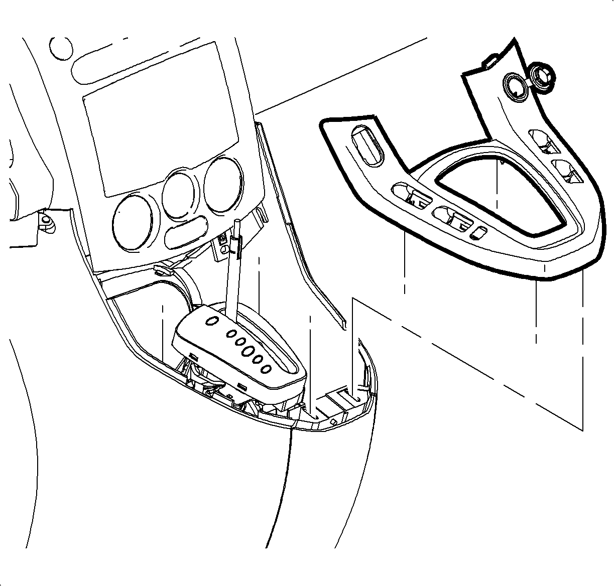
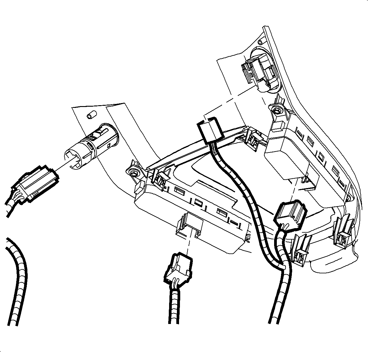
- Pull up at rear edge of horseshoe bezel, first disengaging retention clips up over shifter assembly, then down and back at front to gain access to underside switch connections.
- Disconnect window switches, mirror switch and cigar lighter. Remove horseshoe bezel. Move the shifter back into the park position.
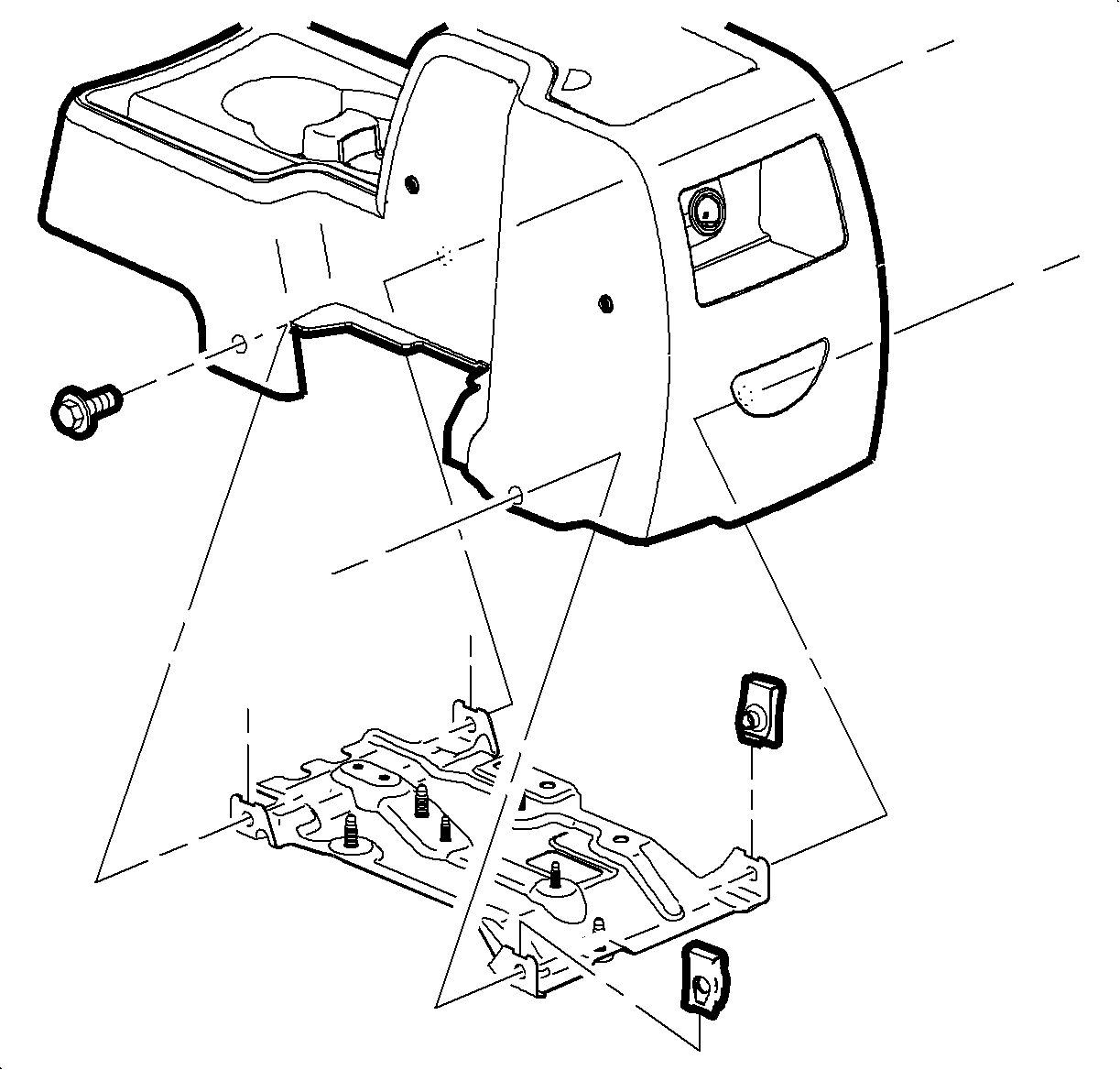
- Remove front floor console screws and slide console rearward.
- Pull rearward at clip location to remove center trim panels.
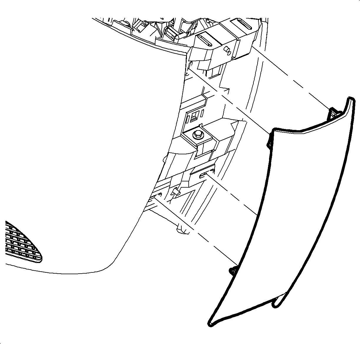
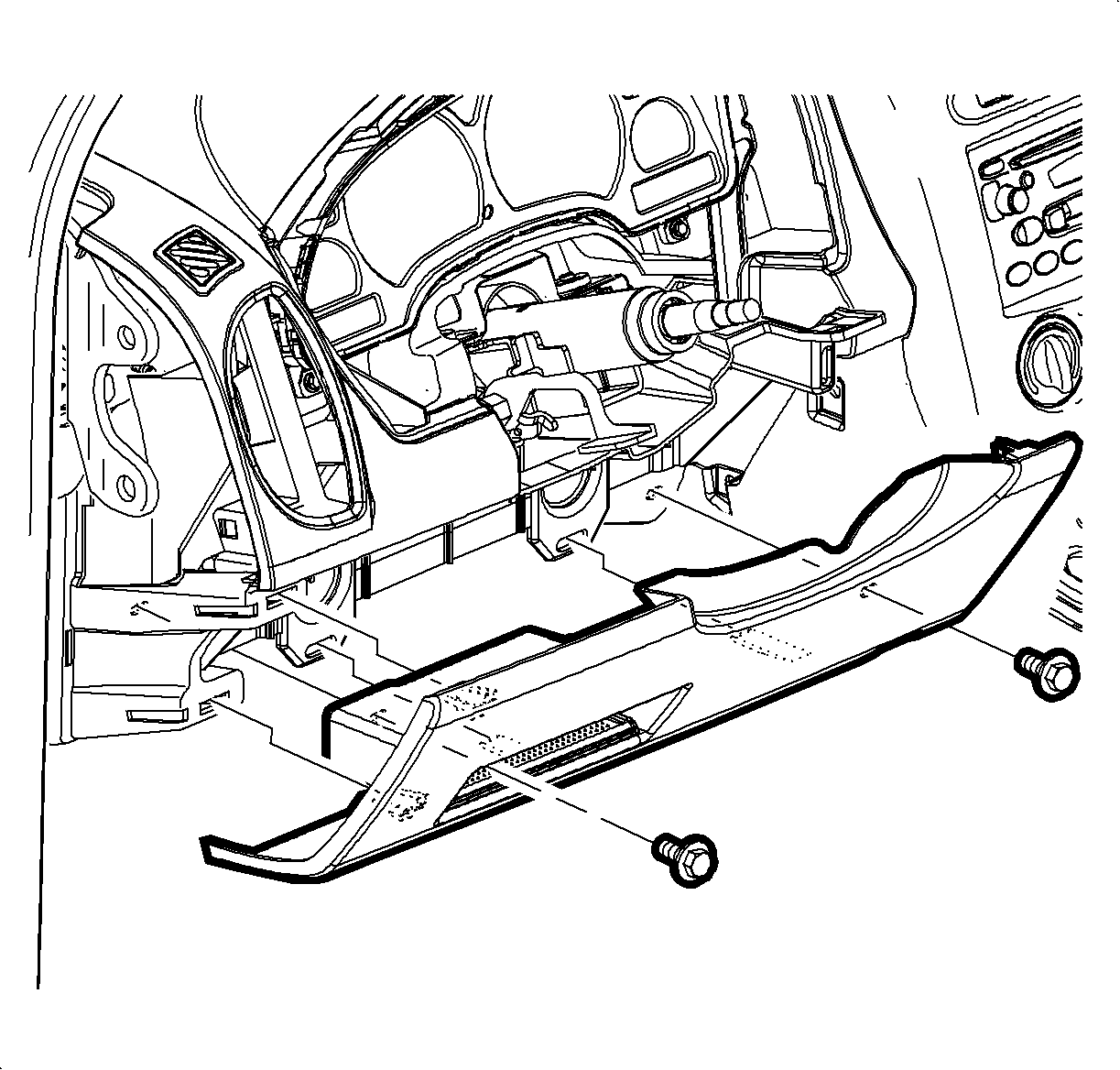
- Remove I/P filler panel (knee bolster).
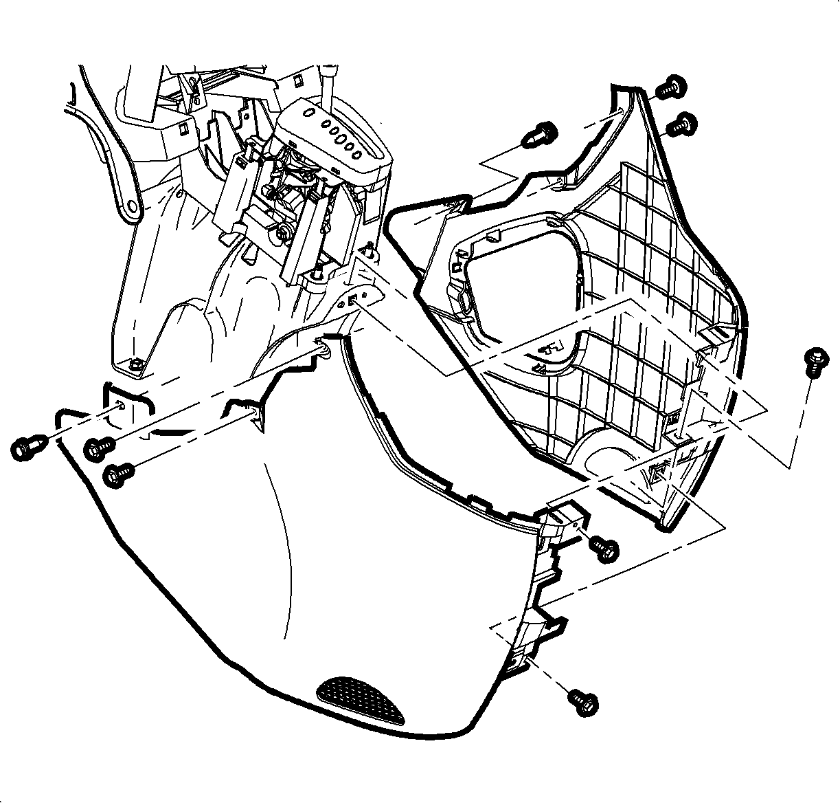
- Remove left and right shifter closeout panels.
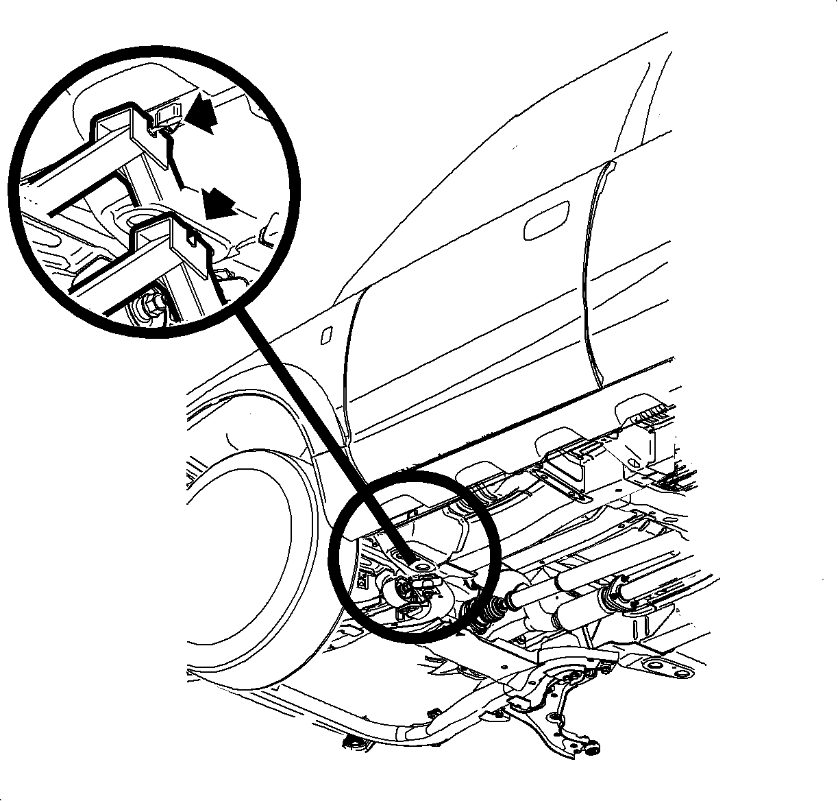
- To duplicate the condition, raise driver side of vehicle. Using a floor jack, measure from the driver side front pinch weld area to floor and raise the vehicle to a total height of 16 in. (406 mm) (approximately 5 degrees of tilt). With fan in "Low" position, the temperature setting on Full Cold with the recirculation feature Off, run air conditioner compressor in high humidity condition (greater than 70%) for approximately 15 minutes.
- After the 15 minute time is up, turn fan speed to "High". Inspect for condensation leak at suspect location of HVAC module seam. If complaint can be duplicated, proceed to next step. If complaint cannot be duplicated, interview customer for additional information that may aid in diagnosing the concern. Refer to the Windnoise, Waterleak and Appearance section of the 2002 VUE Body Removal and Installation Service Manual for more information.
- Lower vehicle.
- Remove instrument panel fuse block (IPFB) from bracket.
- Remove IPFB bracket (2 fasteners).
- Remove the two heater duct screws.
- Remove three screws from the right (passenger) side of the heater core cover (1B).
- Remove three screws on the left (driver) side of the heater core cover (1C).
- Remove the heater core cover screw which is also the bottom mounting screw for the floor mode actuator (1H).
- Partially remove the center trim panel by pulling trim panel at clip locations to disengage clips. Six clips are integral to the trim panel. Slightly rotate trim panel to access back of panel.
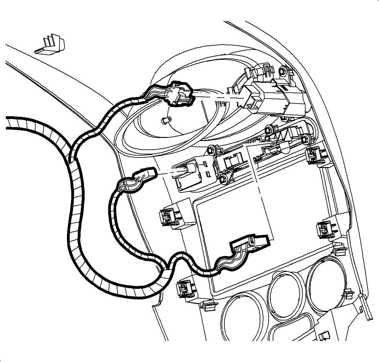
- Disconnect hazard switch connector.
- Disconnect dimming control connector.
- Disconnect traction control switch (if equipped).
- Disconnect fog lamp switch connector (if equipped).
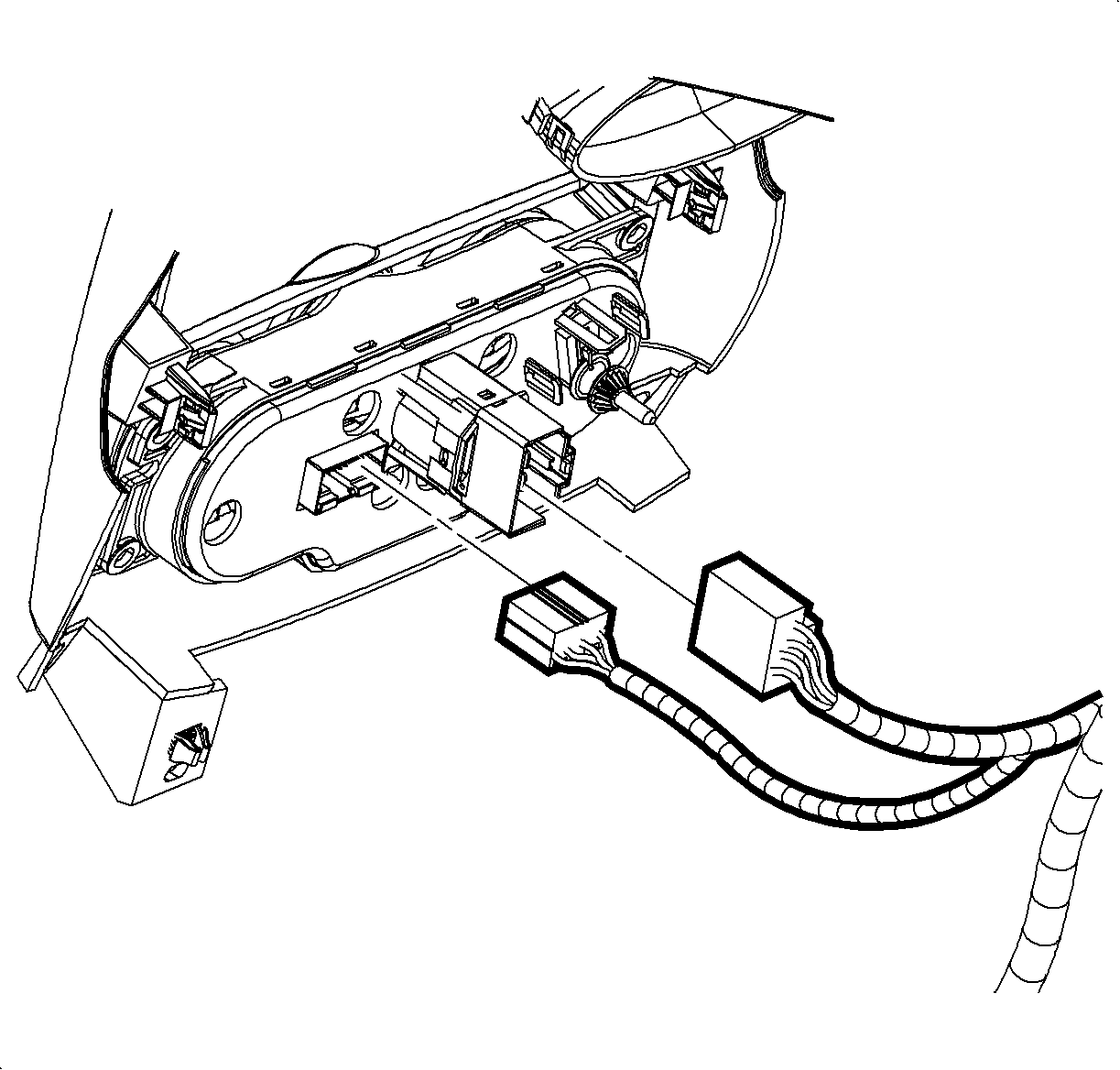
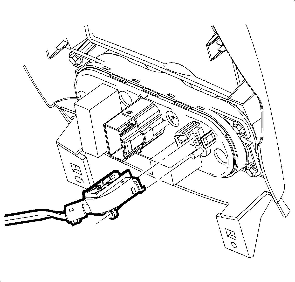
- Disconnect HVAC control electrical connectors.
- Disconnect HVAC cable from HVAC head controller. Set center trim panel aside.
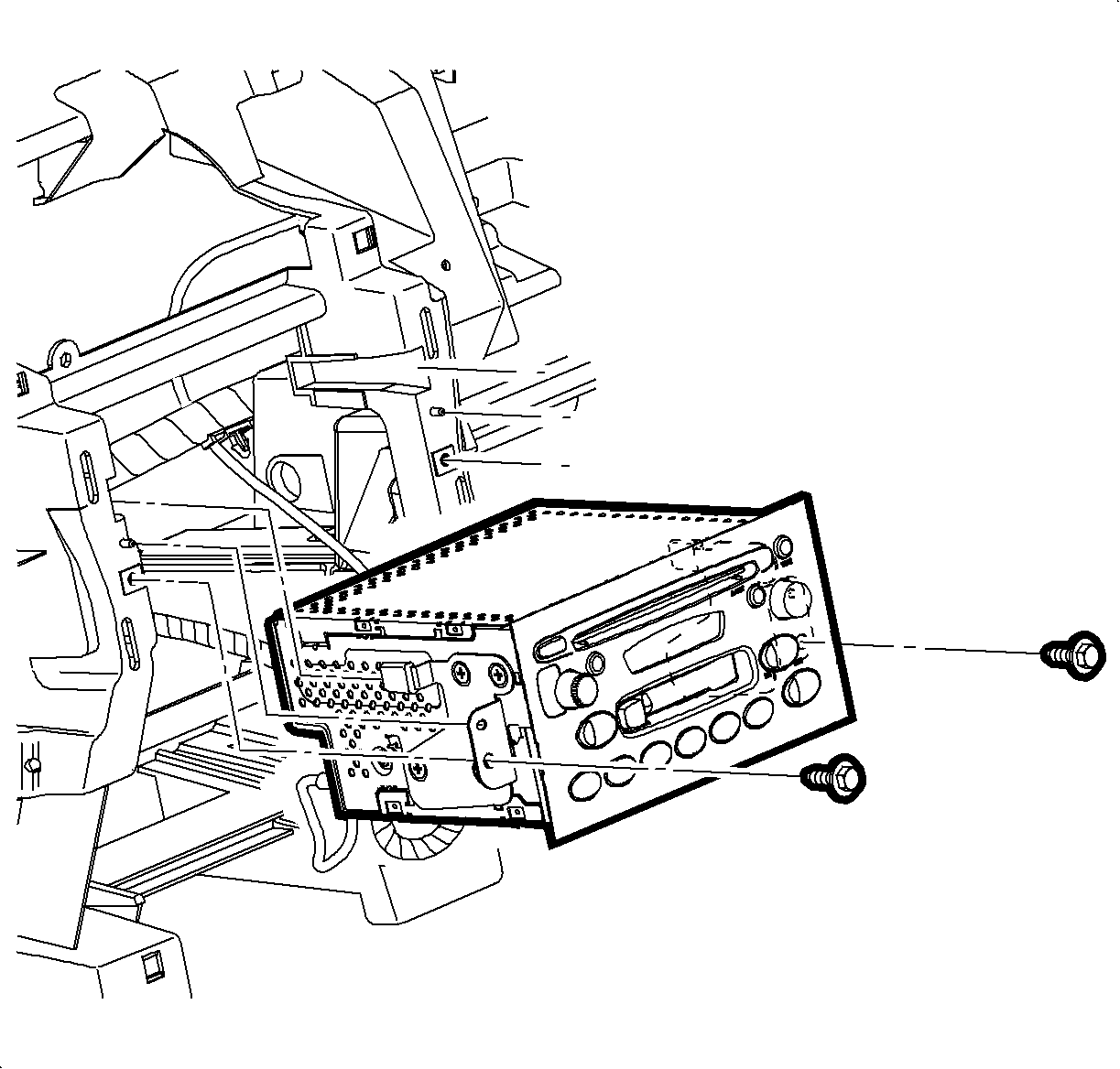
- Remove two fasteners securing radio.
- While providing support, partially remove radio to obtain access to back of radio.
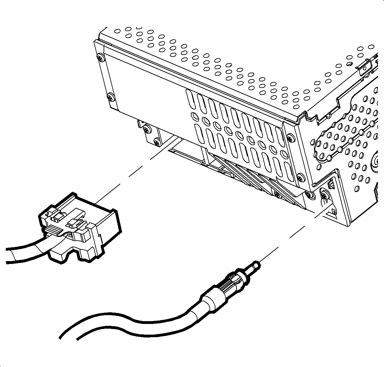
- Disconnect radio connectors.
- Disconnect antenna connector.
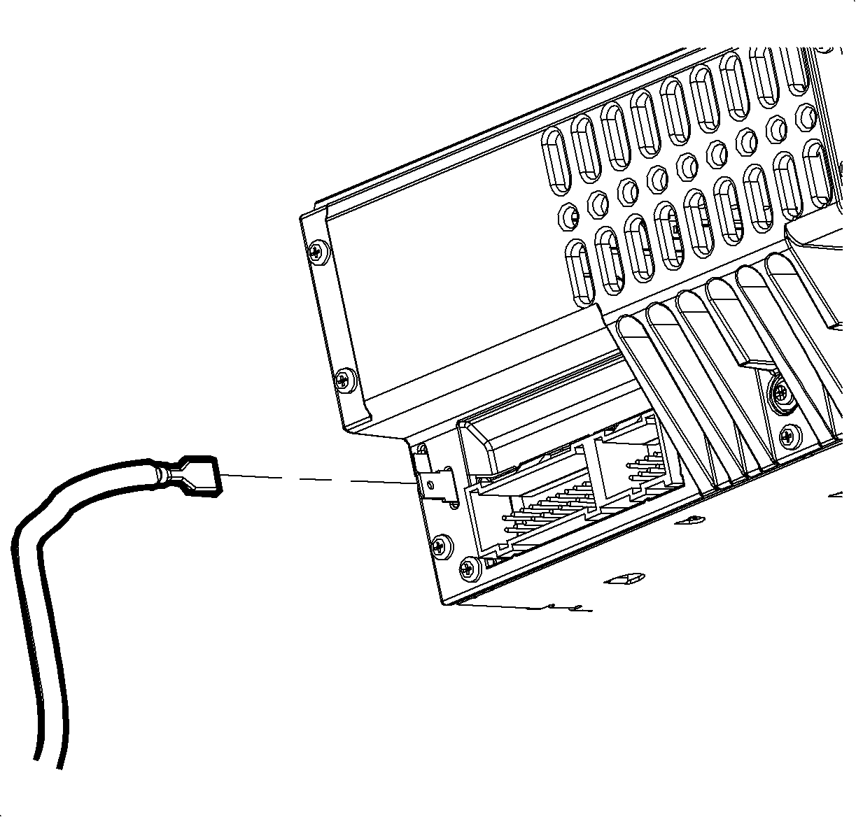
- Disconnect ground strap blade connector. The radio can now be removed.
- Remove heater core cover fastener located behind radio next to floor mode actuator (1H).
- Unlatch the three clips from the front of the heater core cover (1D).
- Remove heater core cover.
- Remove heater core pipe cover and slide foam insulator rearward.
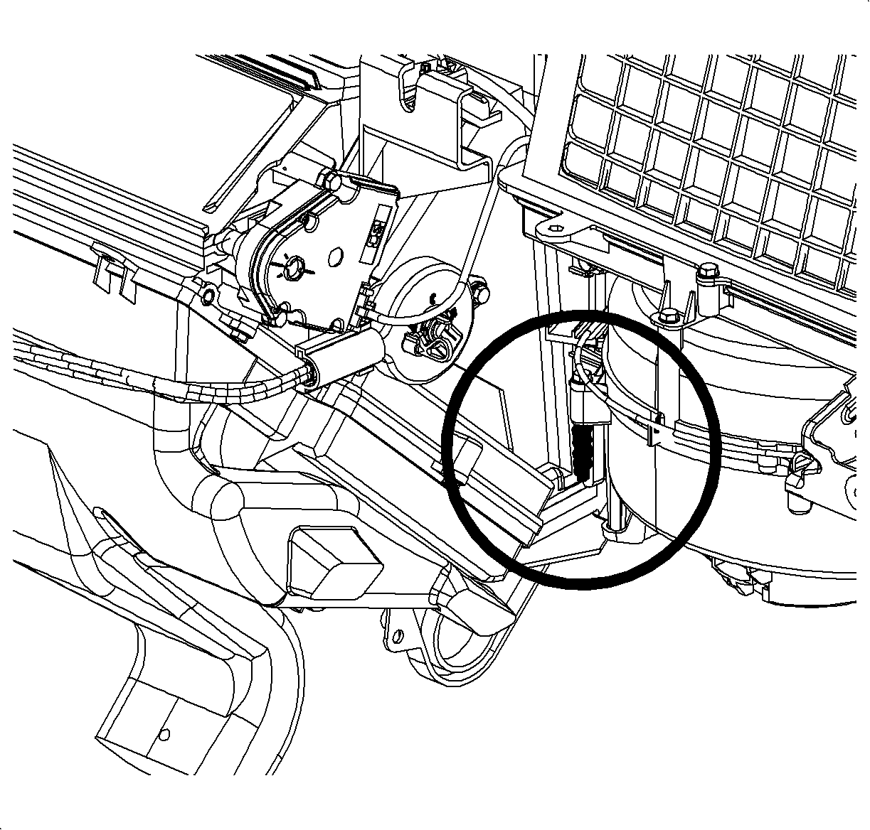
- Apply 3M® 5200 sealant (P/N 22706496) around the perimeter of the heater core cover as bolded in illustration.
- Reinstall the heater core cover.
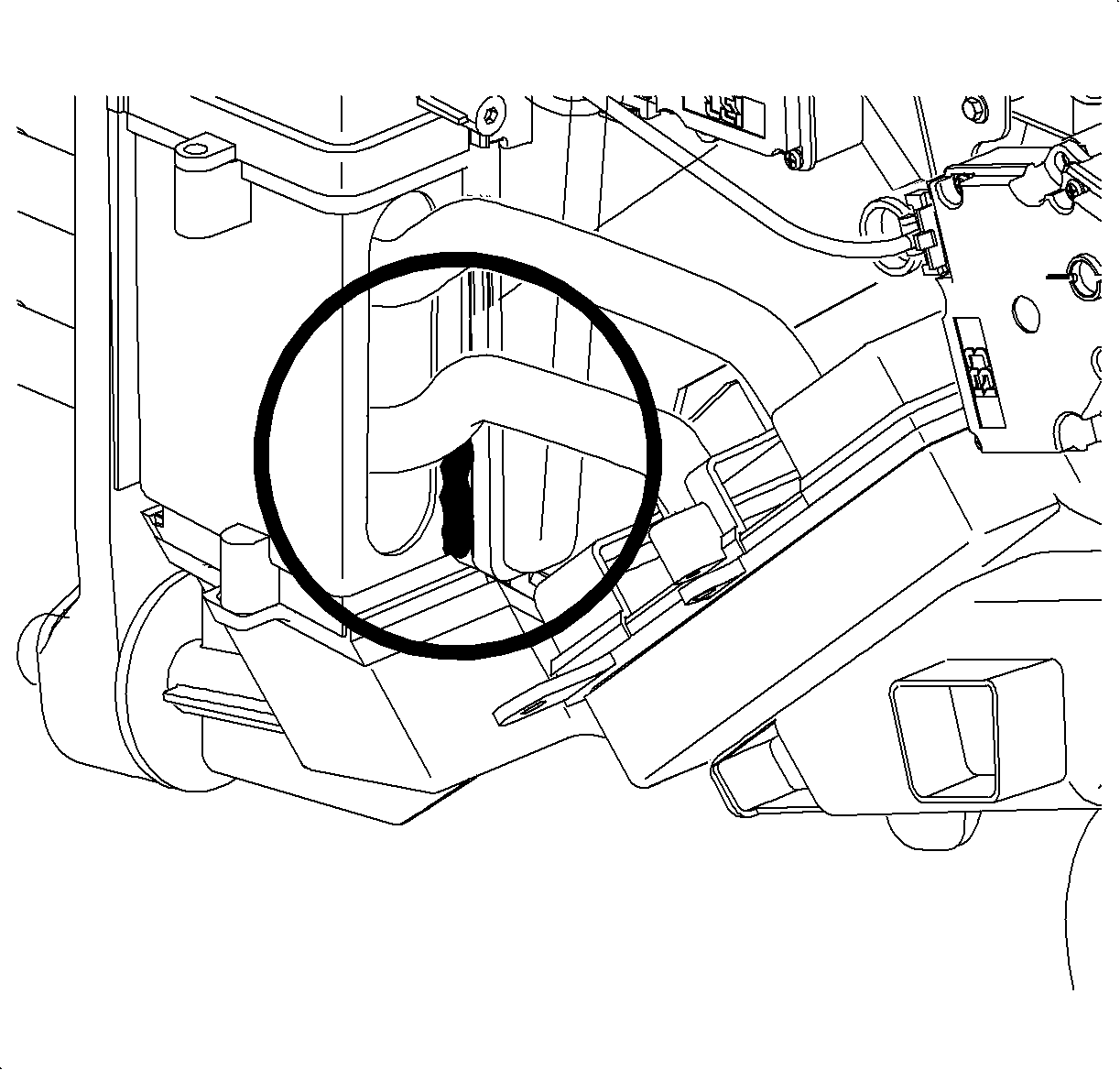
- After the heater core cover is reinstalled, apply a 4 in. (102 mm) bead of 3M® 5200 sealant (P/N 22706496) on the exterior of the case on the evaporator core cover right vertical seam. Note: The bottom edge of the 4 in. (102 mm) bead of sealant should overlap the heater core cover seal. The overlap will ensure good sealant coverage at this location.
- Apply a 4 in. (102 mm) bead of 3M® 5200 sealant (P/N 22706496) on the exterior of the case on the evaporator core cover left vertical seam. Note: The bottom edge of the 4 in. (102 mm) bead of sealant should overlap the heater core cover seal. The overlap will ensure good sealant coverage at this location.
- Reinstall heater core pipe cover and foam insulator.
- While providing support, access the back of radio.
- Reconnect radio connectors.
- Reconnect antenna connector.
- Reconnect ground strap blade connector.
- Install two fasteners securing radio.
- Reconnect hazard switch connector.
- Reconnect dimming control connector.
- Reconnect traction control switch (if equipped).
- Reconnect fog lamp switch connector (if equipped).
- Reconnect HVAC control electrical connectors.
- Reconnect HVAC cable from HVAC head controller. Replace center trim panel.
- Validate the repair by raising the driver side of vehicle. Using a floor jack, measure from the driver side front pinch weld area to raise the vehicle to a total height of 16 in. (406 mm) (approximately 5 degrees of tilt). With fan in "Low" position, run A/C compressor in high humidity condition for approximately 15 minutes. Turn the fan speed to "High". Inspect for condensation leak at suspect location of HVAC module seam. If the seam leaks, add sealant to the exterior of the seam as required.
- Lower vehicle.
- Install heater duct.
- Install wire harness back on stud by pushing retainer onto the stud.
- Install IPFB bracket.
- Install instrument panel fuse block (IPFB).
- Install I/P ground from H-brace.
- Install right and left shifter closeout panels.
- Install center shifter closeout panel.
- Connect wire harness to window switches, mirror switch, and cigar lighter.
- Move shifter to neutral position.
- Install front edge of horseshoe bezel first over shifter assembly. Make sure to engage alignment pins and front edge tabs with corresponding slots at bottom of radio bezel. Clear wires and lower back edge by pressing down and snapping into place.
- Slide console forward and install console screws.
- Install I/P filler panel (knee bolster) by aligning retention tabs on panel with corresponding slots in retainer and pressing forward at clip locations to snap into place.
- Install filler panel to retainer screws.
Caution: Be sure to apply the parking brake before performing procedure.
Leak Sealing Procedure
Note: Prior to removing heater core cover, put HVAC mode in panel mode position. This closes the floor mode door which will eliminate interference between heater core cover and floor mode door when the heater core cover is removed.
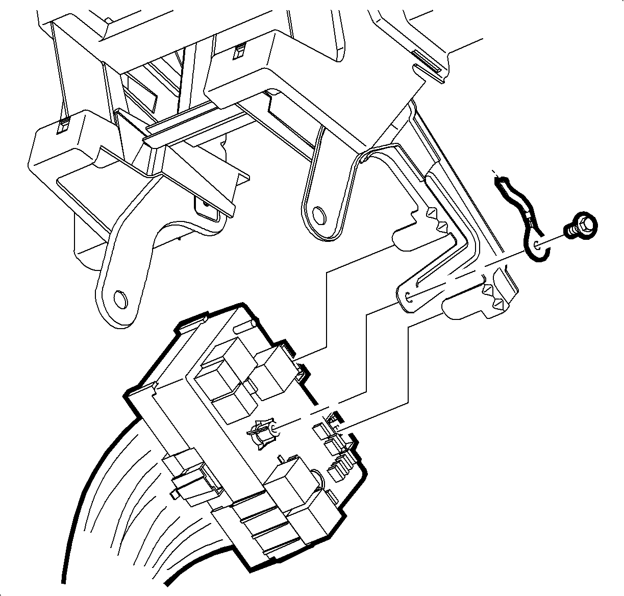
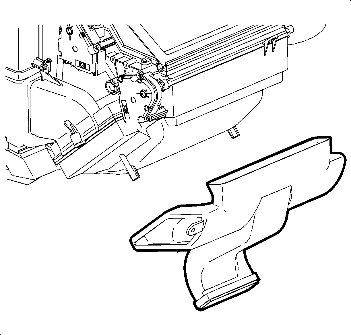
Note: The I/P wire harness is attached to the left side heater duct screw/stud. Pull the retainer straight off the stud to remove wire harness.
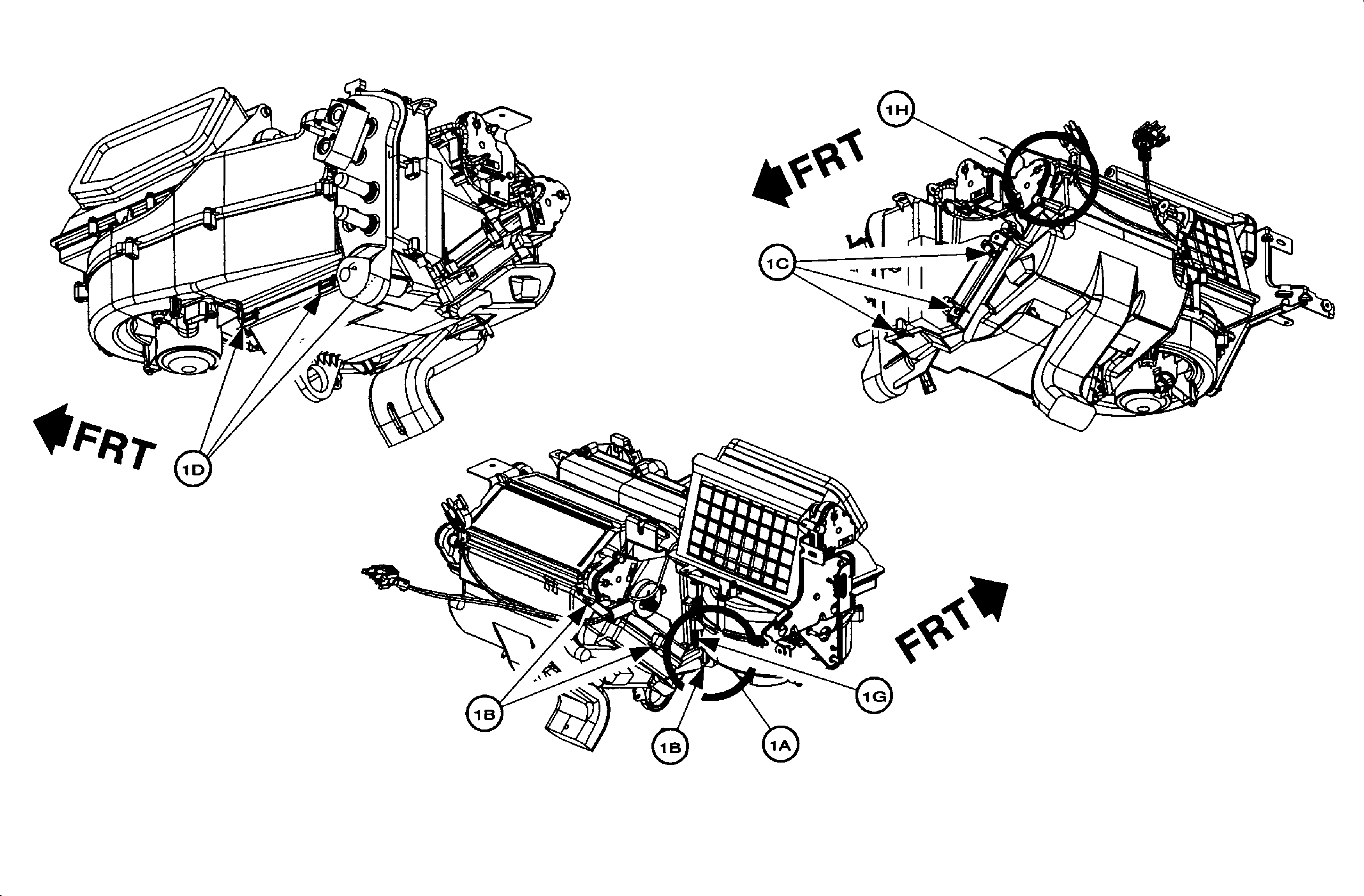
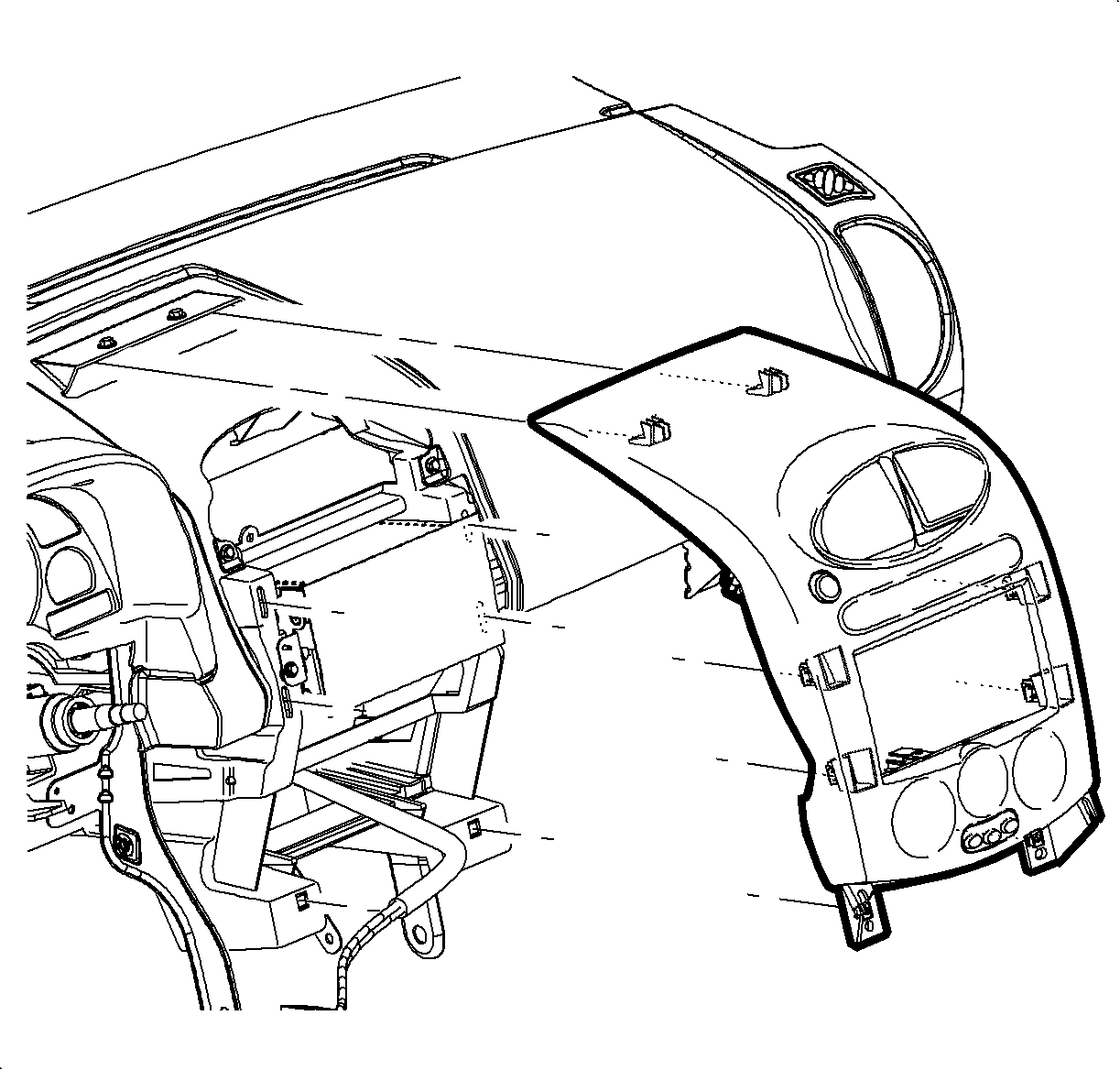
Important: To gain access to the fifth heater core cover screw, the radio must be removed.
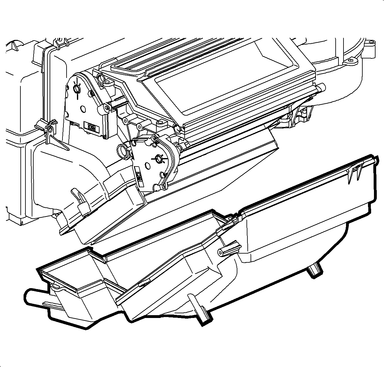
Note: Some vehicles built prior to the breakpoint have had sealant applied to the heater core covers during manufacturing of the HVAC module. If the cover still leaks condensation and sealer has previously been applied, clean all old sealer prior to applying the new sealer.
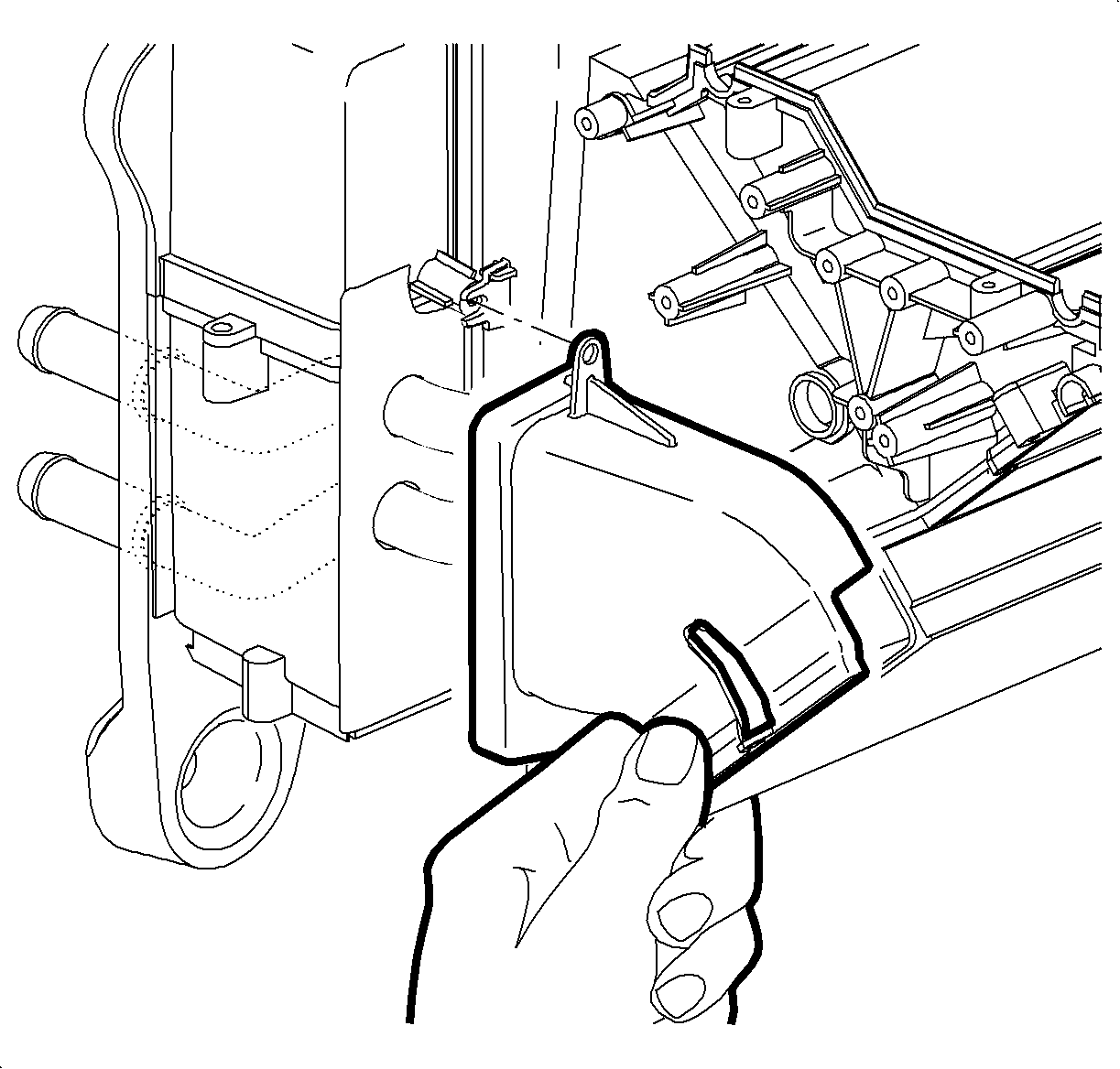
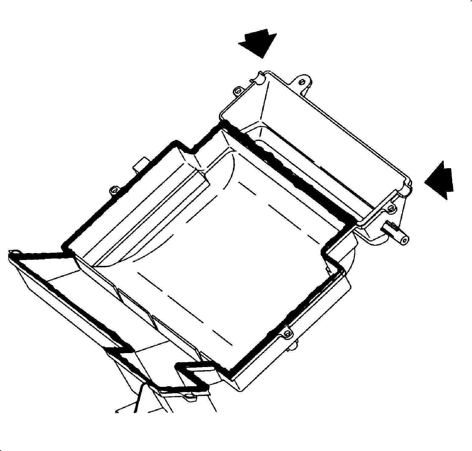
Note: Do not apply sealant around the floor mode damper shaft locations as indicated with arrows.

Tighten
Tighten the heater core cover screws to 1 N·m (9 lb in).



Tighten
Tighten the I/P ground to H-brace to 10 N·m (88 lb in).

Tighten
Tighten the shifter closeout panel screws to 2.5 N·m (22 lb in).


Tighten
Tighten the retainer screws to 2.5 N·m (22 lb in).
Parts Requirements
22706496* | Sealer, A/C Evaporator Asm Cover (3M® 5200 Sealant) in U.S.A. |
* Retailers in Canada use 3M® 5200 Sealant (P/N 06504, Black) obtained locally or contact 3M at 1-800-364-3577. |
Claim Information
To receive credit for this repair during the warranty coverage period, submit a claim through the Saturn Dealer System for D2480 (Case, HVAC - Repair), or if another procedure is performed, refer to the appropriate Electronic Labor Time Guide for the correct Labor Operation Code and Time.
