(MIL) Service Engine Soon Telltale Lamp On, Reduced Power Lamp May Illuminate with DTCs P0121,P0221 and/or P2135 (Replace Throttle Body, Throttle Body Connector, Throttle Body Terminals and Install

| Subject: | (MIL) Service Engine Soon Telltale Lamp On, Reduced Power Lamp May Illuminate with DTCs P0121, P0221, and/or P2135 (Replace Throttle Body, Throttle Body Connector, Throttle Body Terminals and Install Throttle Body Pigtail Retainer to Throttle Body and Harness) |
| Models: | 2000-2003 Saturn L-Series |
| 2002-2003 Saturn VUE Vehicles |
| with 3.0L V6 Engine (VIN R -- RPO L81) |
| Attention: | General Manager, Fixed Operations Manager, Parts Manager, Technician |
Condition
Some customers may comment the (MIL) SERVICE ENGINE SOON and Reduced Power Lamp may come on intermittently and/or stay on. DTCs P0121, P0221 and/or P2135 may be set.
Cause
This condition may be caused by loose or poor terminal tightness at the engine harness-to-throttle body connection.
Correction
Refer to the Saturn VUE L81 or the Saturn L-Series L81 service procedure in this bulletin.
Service Procedure for Saturn VUE L81
- Disconnect negative battery cable.
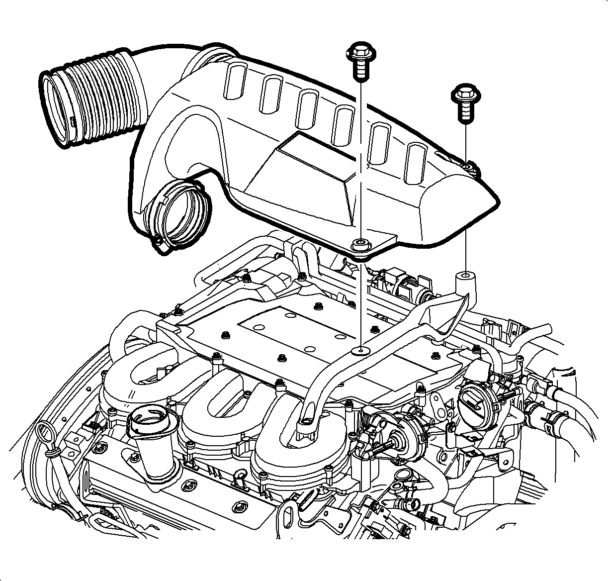
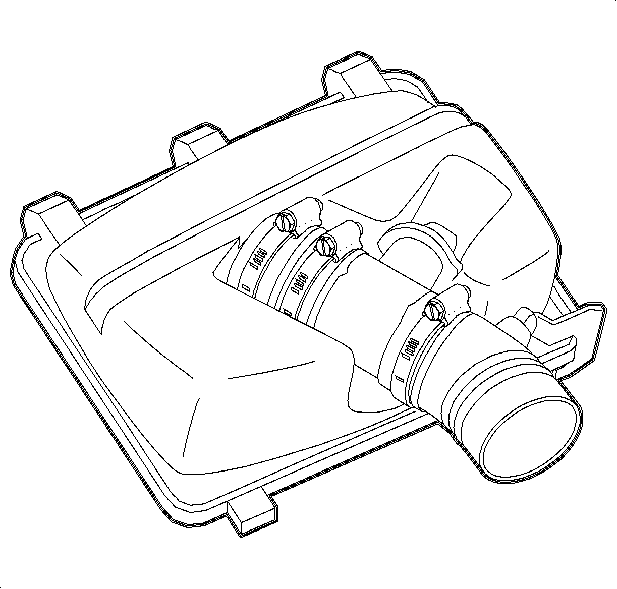
- Loosen clamp at air cleaner assembly and throttle body assembly.
- Remove attachment bolts from outlet resonator/duct assembly to support bracket.
- Remove outlet resonator/duct assembly.
- Cover throttle body opening with a shop towel and use shop air to remove any dirt at the base of the throttle body.
- Disconnect throttle body electrical connector.
- Disconnect Positive Crankcase Ventilation (PCV) fresh air hose at throttle body.
- Remove purge and PCV vacuum lines.
- Clamp coolant inlet and outlet hoses with pinch-off tool to avoid leaking coolant on engine.
- Remove coolant hoses at throttle body.
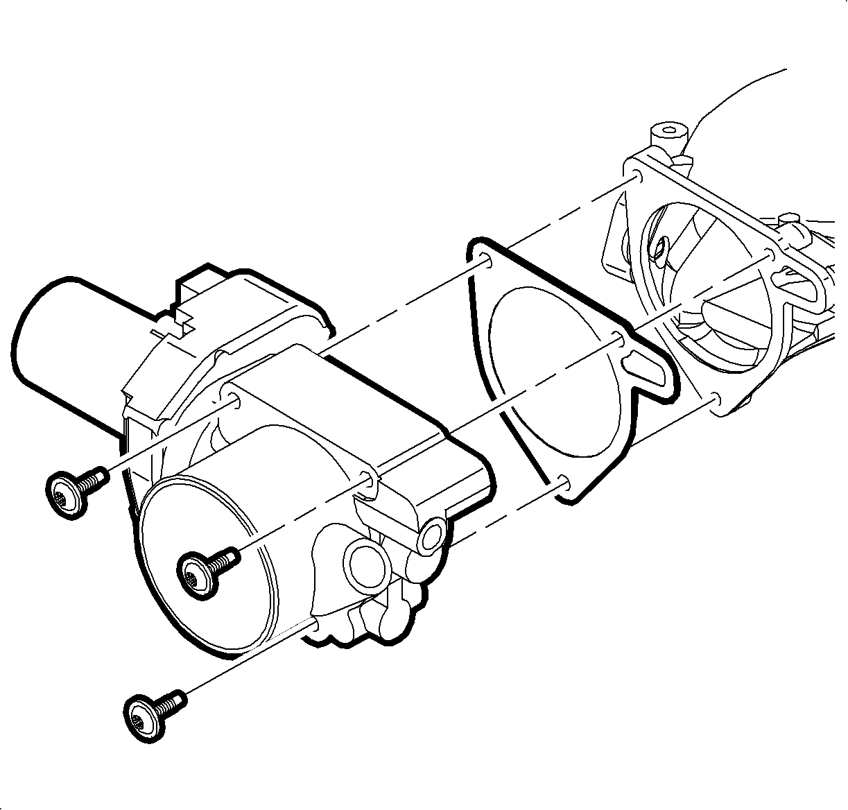
- Remove throttle body bolts.
- Remove throttle body.
- Remove throttle body gasket.
- Install new throttle body gasket, P/N 24446587.
- Install new throttle body assembly, P/N 24446586.
- Tighten throttle body bolts.
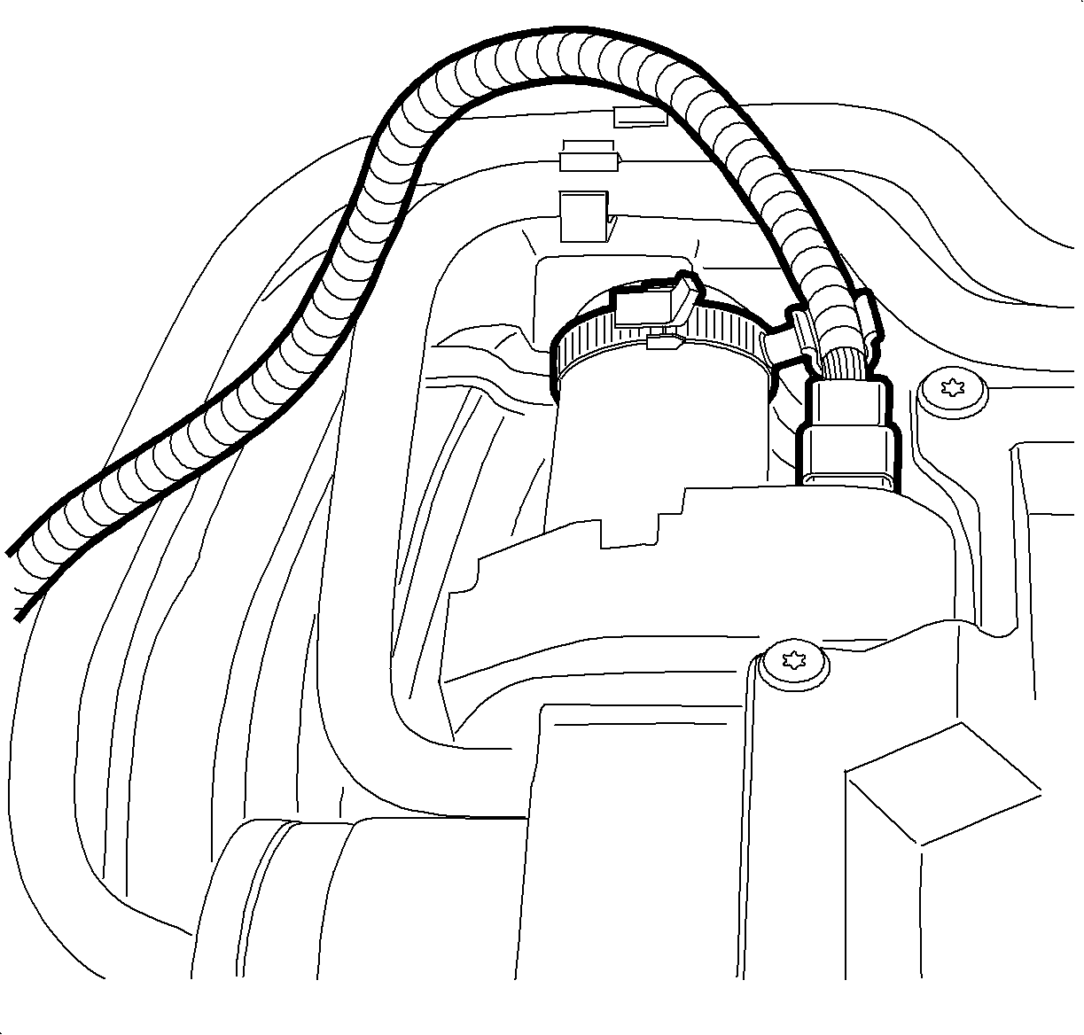
- Install throttle body harness retainer, P/N 22729513, to throttle body motor.
- Position stand off clip inline with throttle body connector.
- Attach coolant hoses to throttle body assembly.
- Remove hose pinch-off tool to allow coolant flow to throttle body.
- Connect PCV fresh air and vacuum lines.
- Remove engine harness from metal harness retainer on intake manifold.
- Remove tape and conduit 457.2 mm (18 in.) from throttle body connector.
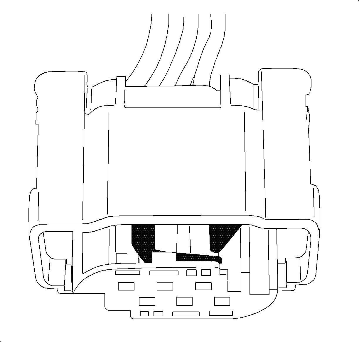
- Ensure green terminal retainers of new throttle body connector, P/N 22720050, are in released position to insert terminals.
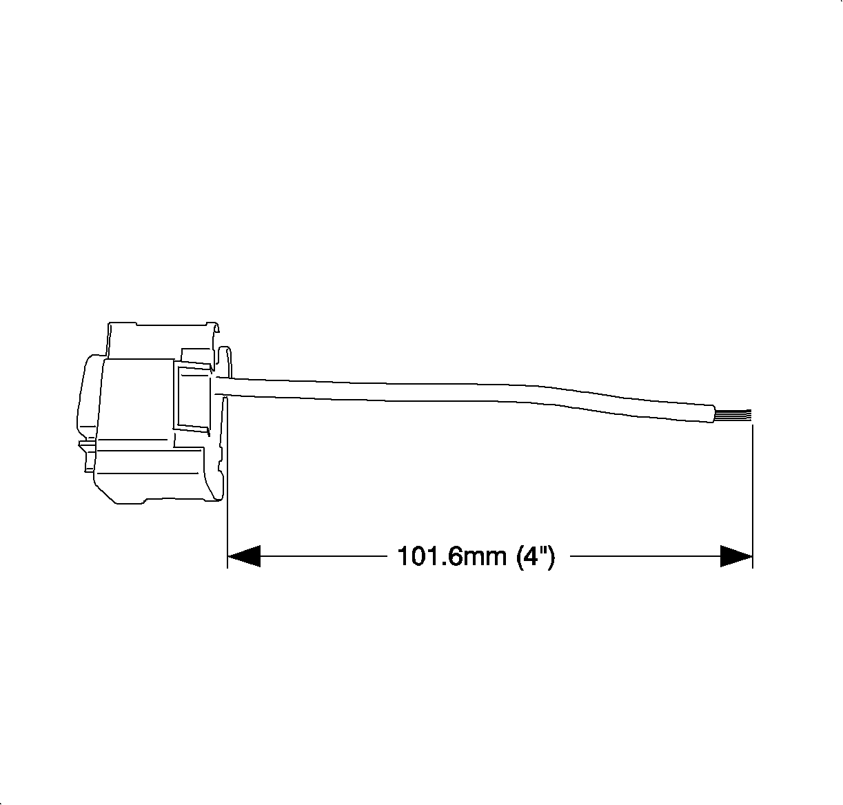
- Cut ckt 581 YEL terminal #1 throttle body connector 101.6 mm (4 in.) from connector on engine harness.
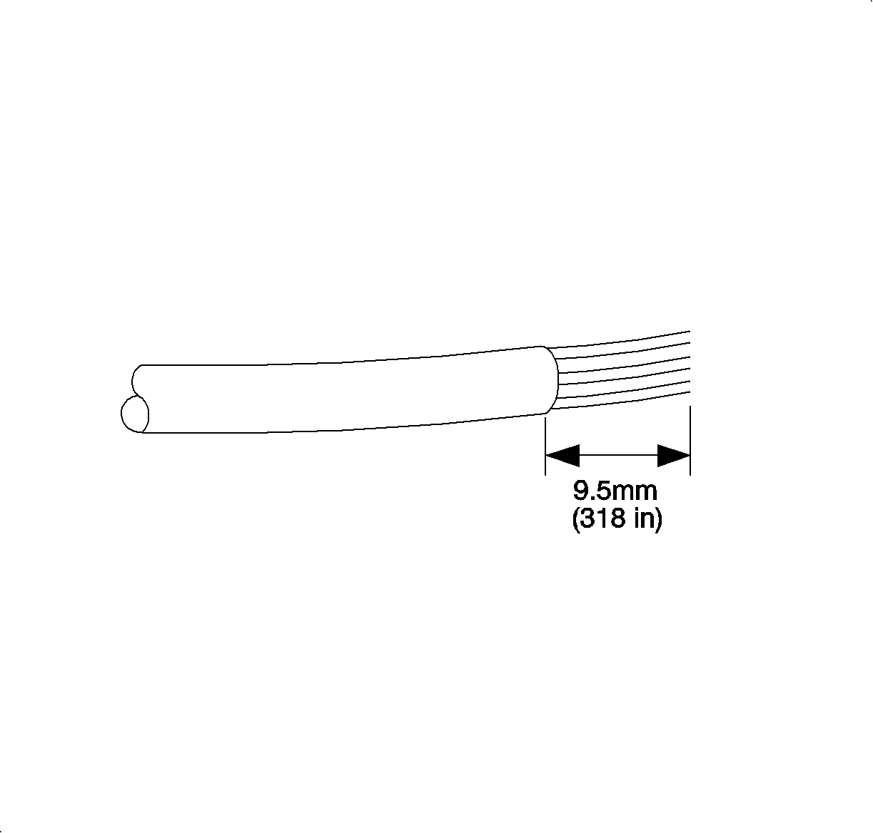
- Remove insulation from end of cut wire. Recommended strip length is 9.5 mm (3/8 in.).
- Install splice sleeve included in terminal lead, P/N 22690873, by positioning stripped end of engine harness ckt 581 into sleeve until wire hits stop in center of the splice sleeve.
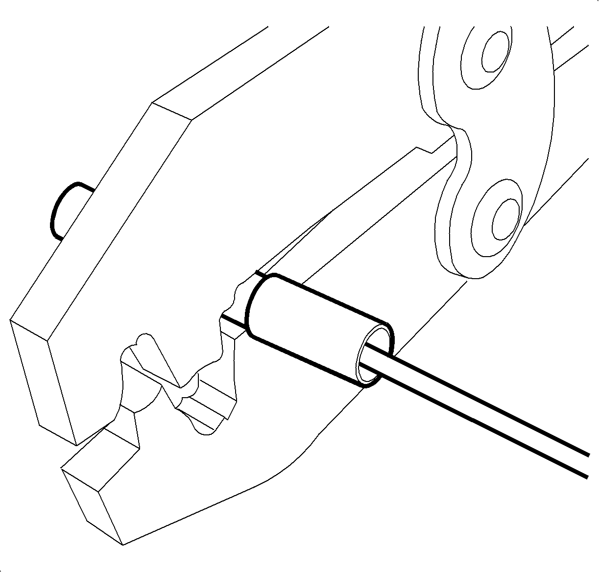
- Hand crimp sleeve using the approved crimping tool (found in terminal repair kit J-44020). Gently tug on wires to make sure they are secure.
- Cut new terminal lead, P/N 22690873, to 101.6 mm (4 in.) and insert in terminal location #1 of new throttle body connector, P/N 22720050.
- Remove insulation from end of cut wire 9.5 mm (3/8 in.) and insert stripped end in splice sleeve for ckt 581.
- Hand crimp sleeve to new replacement wire for ckt 581. Gently tug on wires to make sure they are secure prior to applying heat.
- Cut ckt 582 BRN terminal #4 throttle body connector 127 mm (5 in.) from connector.
- Cut new terminal lead, P/N 22690873, to 127 mm (5 in.) and insert terminal location #4 of throttle body connector, P/N 22720050.
- Repeat above crimping procedure for ckt 582.
- Cut ckt 2752 BLK terminal #2 throttle body connector 254 mm (10 in.) from connector.
- Cut new terminal lead, P/N 22690873, to 254 mm (10 in.) and insert in terminal location #2 of throttle body connector, P/N 22720050.
- Repeat above crimping procedure for ckt 2752.
- Cut ckt 2701 GRA terminal #3 throttle body connector 304 mm (12 in.) from connector.
- Cut new terminal lead, P/N 22690873, to 304 mm (12 in.) and insert in terminal location #3 of throttle body connector, P/N 22720050.
- Repeat above crimping procedure for ckt 2701.
- Cut ckt 486 PPL terminal #5 throttle body connector 355.6 mm (14 in.) from connector.
- Cut new terminal lead, P/N 22690873, to 355.6 mm (14 in.) and insert in terminal location #5 of throttle body connector, P/N 22720050.
- Repeat above crimping procedure for ckt 486.
- Cut ckt 485 DK GRN terminal #6 throttle body connector 406.4 mm (16 in.) from connector.
- Cut new terminal lead, P/N 22690873, to 406.4 mm (14 in.) and insert in terminal location #6 of throttle body connector, P/N 22720050.
- Repeat above crimping procedure for ckt 485.
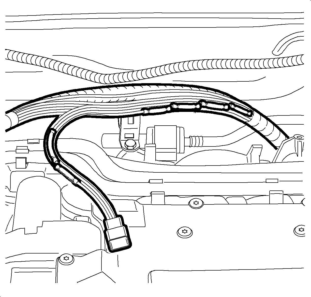
- Apply heat using a heat gun, or equivalent, and heat to 175°C (347°F) until glue flows down around edges of sleeves for each ckt.
- Move terminal retainers of new throttle body connector, P/N 22720050, to locked position to secure terminals.
- Wrap wires with tape and insert into conduit.
- Apply tape to conduit to retain wires.
- Install engine harness in metal harness retainer on intake manifold.
- Connect throttle body electrical connector.
- Insert throttle body harness into throttle body harness retainer, P/N 22729513, on throttle body motor.
- Install outlet resonator/duct assembly into position.
- Tighten clamp at throttle body assembly.
- Position outlet resonator/duct assembly to support bracket and install bolts.
- Tighten clamp at air cleaner assembly.
- Connect negative battery cable.
- The automatic relearn procedure must be completed by the engine control module (ECM).
- To complete this relearn procedure, turn ignition to "RUN" position for one minute.
- Verify proper coolant level and add if necessary.
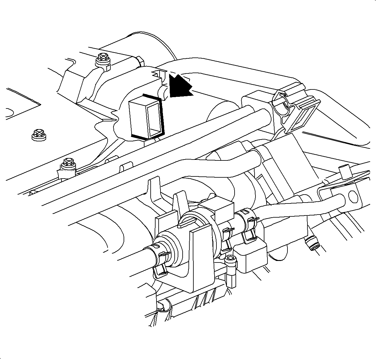
Notice: Damaged or broken throttle body connector retainer clips may result with intermittent electrical connection and (MIL) Service Engine Soon Telltale Lamp or Reduced Power Lamp illuminating.
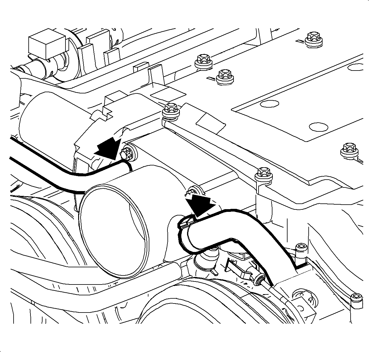
Notice: Cover the intake manifold opening with a shop towel whenever the throttle body is removed to prevent foreign material entry.

Notice: Use care when tightening throttle body bolts. Manifold damage will result if over torqued.
Tighten
Tighten the Throttle Body-to-Intake Manifold Bolts-L81
to 7.5N·m(66 in-lbs).

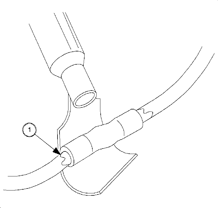
Caution: DO NOT USE MATCH OR OPEN FLAME TO APPLY HEAT TO SEAL.
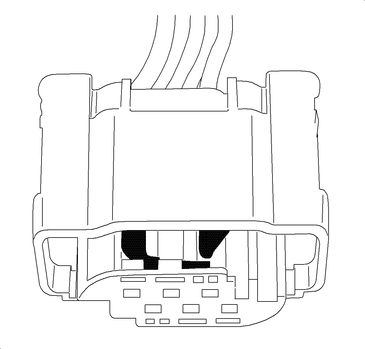

Notice: Damaged or broken throttle body connector retainer clips may result with intermittent electrical connection and (MIL) Service Engine Soon Telltale Lamp or Reduced Power Lamp illuminating.

Tighten
Tighten the Outlet Resonator/Duct Assembly-to-Support
Bracket Bolts-L81 to 10N·m(89 in-lbs).
Tighten
Tighten the Battery Terminal Bolt to 17N·m(13
ft-lbs).
Important: Do not depress the accelerator pedal assembly during the automatic relearn procedure.
| • | Ignition "ON", engine "OFF" for longer than 29 seconds |
| • | Make sure these engine operating parameters are met before proceeding: |
| - | ECT between 5° and 100° C (41° and 212° F) |
| - | IAT greater than 5° C (41° F) |
| - | Ignition voltage above 10 volts. |
| - | Accelerator pedal angle is less than 15%. |
Service Procedure for Saturn L-Series L81
- Disconnect negative battery cable.
- Remove air cleaner and inlet hose assembly from throttle body.
- Disconnect throttle body electrical connector.
- Disconnect hose clamps from plenum-to-runner connector using universal clamp pliers J-43914.
- Remove intake plenum bolts.
- Remove EGR pipe bolt.
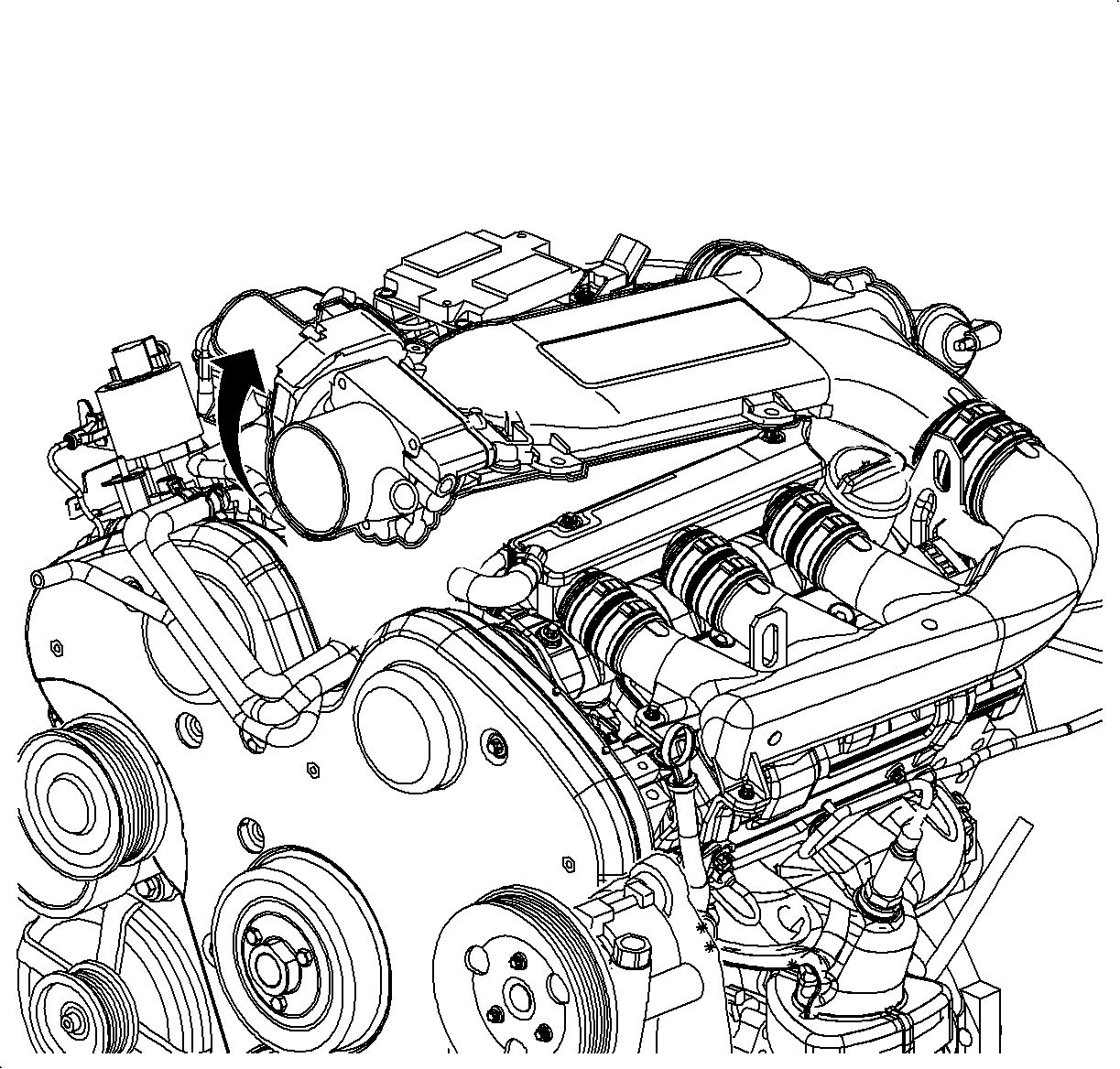
- Rotate plenum up and remove throttle body coolant hoses, EVAP hose, and vacuum lines from throttle body.
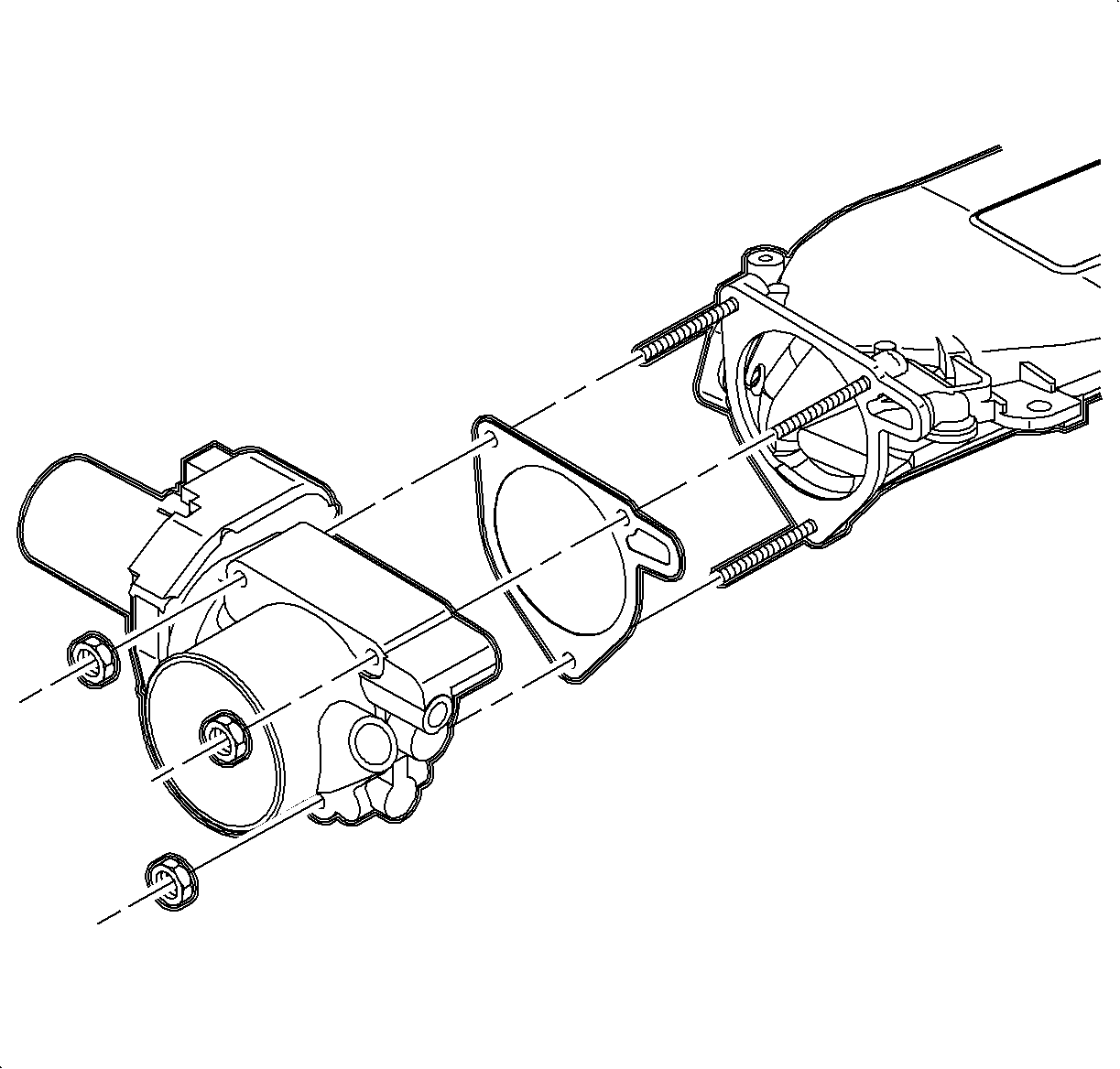
- Remove throttle body nuts.
- Remove throttle body.
- Remove throttle body gasket.
- Install new throttle body gasket, P/N 90571137.
- Install new throttle body assembly, P/N 13105809.
- Install throttle body nuts.
- Attach vacuum lines, EVAP hose, and coolant hoses to throttle body.
- Ensure O-ring on the lower manifold is correctly seated.
- Install EGR pipe bolt.
- Install intake plenum bolts.
- Connect hose clamps from intake plenum-to-runner rubber boots using universal clamp pliers tool J-43914. If clamps are damaged, replace with service screw type clamps.
- Install air cleaner inlet hose.
- Remove tape and conduit 228.6 mm (9 in.) from throttle body connector.
- Ensure green terminal retainers of new throttle body connector, P/N 22720050, is in released position to insert terminals.
- Cut ckt 581 YEL terminal #1 throttle body connector 63.5 mm (2 1/2 in.) from connector on engine harness.
- Remove insulation from end of cut wire. Recommended strip length is 9.5 mm (3/8 in.).
- Install splice sleeve included in terminal lead, P/N 22690873, by positioning stripped end of engine harness ckt 581 into sleeve until wire hits stop in center of the splice sleeve.
- Hand crimp sleeve using the approved crimping tool (found in terminal repair kit J-44020). Gently tug on wires to make sure they are secure.
- Cut terminal lead, P/N 22690873, to 63.5 mm (2 1/2 in.) and insert in terminal location #1 of new throttle body connector, P/N 22720050.
- Remove insulation from end of cut wire 9.5 mm (3/8 in.) and insert stripped end in splice sleeve for ckt 581.
- Hand crimp sleeve to new replacement wire for ckt 581. Gently tug on wires to make sure they are secure prior to applying heat.
- Cut ckt 582 BRN terminal #4 throttle body connector 63.5 mm (2 1/2 in.) from connector.
- Cut new terminal lead, P/N 22690873, to 63.5 mm (2 1/2 in.) and insert in terminal location #4 of throttle body connector, P/N 22720050.
- Repeat above crimping procedure for ckt 582.
- Cut ckt 652 PPL/WHT terminal #2 throttle body connector 89 mm (3 1/2 in.) from connector.
- Cut new terminal lead, P/N 22690873, to 89 mm (3 1/2 in.) and insert in terminal location #2 of throttle body connector, P/N 22720050.
- Repeat above crimping procedure for ckt 652.
- Cut ckt 486 PPL terminal #3 throttle body connector to 89 mm (3 1/2 in.) from connector.
- Cut new terminal lead, P/N 22690873, to 89 mm (3 1/2 in.) and insert in terminal location #3 of throttle body, P/N 22720050.
- Repeat above crimping procedure for ckt 486.
- Cut ckt (2000-2001) 485 DK BLU (2002-2003) 485 DK GRN terminal #5 throttle body connector to 152.5 mm (6 in.) from connector.
- Cut new terminal lead, P/N 22690873, to 152.5 mm (6 in.) and insert in terminal location #5 of throttle body, P/N 22720050.
- Repeat above crimping procedure for ckt 485.
- Cut ckt 487 YEL/BLK terminal #6 throttle body connector to 152.5 mm (6 in.) from connector.
- Cut new terminal lead, P/N 22690873, to 152.5 mm (6 in.) and insert in terminal location #6 of throttle body, P/N 22720050.
- Repeat above crimping procedure for ckt 487.
- Apply heat using a heat gun, or equivalent, and heat to 175°C (347°F) until glue flows down around edges of sleeves for each ckt.
- Move terminal retainers of new throttle body connector, P/N 22720050, to locked position to secure terminals.
- Wrap wires with tape and insert into conduit.
- Apply tape to conduit to retain wires.
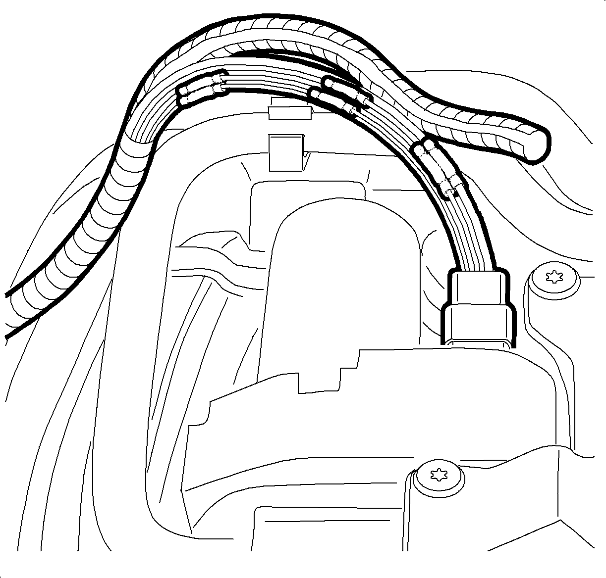
- Install throttle body harness retainer, P/N 22729513, to throttle body motor.
- Position stand off clip inline with throttle body connector.
- Connect throttle body electrical connector.
- Insert throttle body harness into throttle body harness retainer, P/N 22729513, on throttle body motor.
- Connect negative battery cable.
- Perform throttle body relearn procedure as follows:
- Verify proper coolant level and add if necessary.
| Important: Upon replacement of new throttle body, the throttle body relearn procedure must be performed as follows: |
| • | Ignition "OFF" for 10 seconds |
| • | Ignition "ON", engine "OFF" |
| • | Make sure these engine operating parameters are met before proceeding: |
| - | ECT between 6° and 100° C (43° and 212° F) |
| - | IAT greater than 6° C (43° F) |
| - | Ignition voltage above 10 volts. |
| - | Accelerator pedal angle is less than 14%. |
| • | Leave ignition on for one minute with engine off. |
Tighten
Tighten the Throttle Body Nuts to 8 N·m(71 in-lbs).
Tighten
Tighten the EGR Pipe Bolt to 25 N·m(18 ft-lbs).

Tighten
Tighten the Intake Plenum Bolts to 8 N·m(71 in-lbs).

Notice: Damaged or broken throttle body connector retainer clips may result with intermittent electrical connection and (MIL) Service Engine Soon Telltale Lamp or Reduced Power Lamp illuminating.



Caution: DO NOT USE MATCH OR OPEN FLAME TO APPLY HEAT TO SEAL.


Notice: Damaged or broken throttle body connector retainer clips may result with intermittent electrical connection and (MIL) Service Engine Soon Telltale Lamp or Reduced Power Lamp illuminating.

Tighten
Tighten the Battery Terminal Bolts to 17 N·m(13
ft-lbs).
| • | Ignition "OFF" for 10 seconds |
| • | Ignition "ON", engine "OFF" |
| • | Make sure these engine operating parameters are met before proceeding: |
| - | ECT between 6° and 100° C (43° and 212° F) |
| - | IAT greater than 6° C (43° F) |
| - | Ignition voltage above 10 volts. |
| - | Accelerator pedal angle is less than 14%. |
| • | Leave ignition on for one minute with engine off. |
Parts Information
Part Number | Description | Qty |
|---|---|---|
13105809 | Throttle Body L-Series | 1 |
24446586 | Throttle Body VUE | 1 |
90571137 | Throttle Body Gasket L-Series | 1 |
24446587 | Throttle Body Gasket VUE | 1 |
22720050 | Throttle Body Connector | 1 |
|
22690873 | Throttle Body Connector Terminals | 6 |
22729513 | Throttle Body Harness to Throttle Body Retainer | 1 |
Claim Information
To receive credit for any repairs during the warranty coverage period, submit a claim through the Saturn Dealer System for J5490 (Body Unit, Throttle Body - Replace). An "add time" condition is provided to install a new connector and wire leads.
