Customer Satisfaction - Loose VTi Transaxle Converter Housing Bolts

| Subject: | LOOSE VTi TRANSAXLE CONVERTER HOUSING BOLTS |
| Models: | 2003 SATURN VUE VEHICLES EQUIPPED WITH VTi TRANSAXLES |
| Attention: | ALL SATURN RETAILERS AND AUTHORIZED SERVICE PROVIDERS |
Saturn has decided that certain 2003 model year VUE vehicles equipped with VTi transaxles are susceptible to an external fluid leak. This leak is caused by one or more of the torque converter and differential housing to transaxle case assembly fasteners loosening with vehicle use. This leak, when not identified and repaired, may lead to a VTi transaxle failure.
To prevent this condition from occurring, Saturn will replace and properly torque the torque converter housing to transaxle case assembly fasteners. This service will be performed at no cost to the owner.
Vehicles Involved
Only selected 2003 model year Saturn VUE vehicles within the following VIN range will require participation in this program.
3S800203 - 3S859929
You must verify program involvement through your AS400 system. It is important to note that program claims will only be paid on involved vehicles.
Owner Notification
Owners of all involved vehicles will be notified of this customer satisfaction program by Saturn. (Refer to the owner letter included in this bulletin.)
Facility VIN Listing
A list of vehicles assigned to you (Facility VIN Listing), which our records indicate were sold by or shipped to you, (or are located in close proximity to your facility) is enclosed. This listing contains:
| • | Complete vehicle identification number (VIN); and |
| • | VINs of vehicles, which according to Saturn records are in retail stock. |
The Facility VIN Listing is furnished to involved Retailers with the customer satisfaction program bulletin.
Those Retailers not involved initially in this program will receive a message at the top of a blank Facility VIN Listing that states:NO VEHICLES ASSIGNED AT THIS TIME.
Retailer Responsibility
All unsold vehicles in Retailers’ possession and subject to this bulletin must be held at the retail facility and repaired per the service procedure of this bulletin before owners take possession of these vehicles.
In summary, whenever a vehicle subject to this program enters your vehicle inventory, or is in your retail facility for service in the future, please take the steps necessary to be sure the program correction has been made before selling or releasing the vehicle.
Transfer Of Customer Satisfaction Program Responsibility
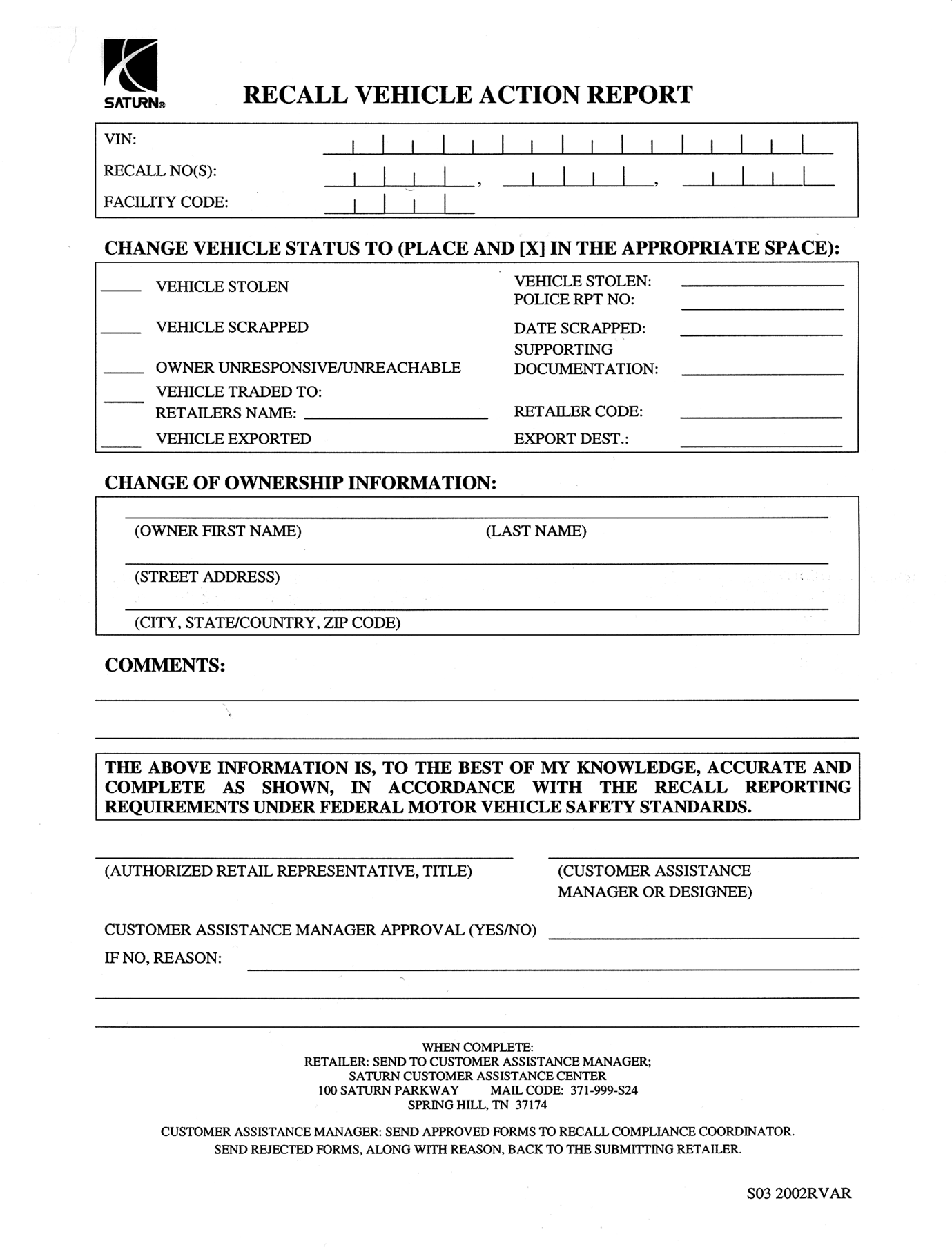
Saturn vehicles that have been sold to you, which may be closer in proximity to another Saturn Retailer, may still appear on your Facility VIN Listing. If you determine that it is more desirable for a vehicle on your Facility VIN Listing to be serviced by another Saturn Retailer, responsibility may be transferred by completing a Recall Vehicle Action Report and submitting it to your Customer Assistance Manager (CAM) at the Saturn Customer Assistance Center.
A copy of the Recall Vehicle Action Report is included for your reference. Additional copies can be ordered from Saturn Publications (1-800-828-2112, prompt 3, Item # S03 2002 RVAR). All changes to program responsibility will be reflected in your next Unfixed VIN Report.
All other changes in vehicle status (e.g., scrapped, stolen, etc.) are to be made in accordance with section 4.4.3 of the Retailer Service Reference Guide, "Notifying Saturn of Vehicle Status Change."
Parts Information
- Please note that not all of the parts below are required for every repair. Refer to the bulletin repair procedures to determine the specific parts needed.
- The majority of the vehicles will require you to perform the "On Vehicle Bolt Replacement" procedure only. Therefore, a pre-shipment of the required parts for this procedure has been automatically sent from Saturn Service Parts Operations (SSPO) to affected retailers.
- Should you require any additional parts, please place an emergency order.
Part Number | Description | Qty/ Vehicle |
|---|---|---|
24227740 | BOLT/SCREW & DIFF HSG | 17-22 |
11588565 | BOLT-HVY HX FLG HDRED BODY | 4 |
Part Number | Description | Qty/ Vehicle |
|---|---|---|
22722716* | SEALER-TRANS CASE GENERIC APPL#1 | 1 |
24225929 | TRANSMISSION ASM-AUTO (FWD) | 1 |
24225928 | TRANSMISSION ASM-AUTO (AWD) | 1 |
22688912 | FLUID-A/TRNS | 4-8 Quarts |
22679307 | CLIP-ATRNS SHFT LVR CBL | 2 |
22697447 | ADDITIVE-A/TRNS FLUID | 1 |
24220892 | PLUG-TRANS FLUID FIL TUBE SHPG | 1 |
10247420 | NUT-STRG LNKG OTR TIE ROD | 2 |
11076671 | SPLIT PIN | 2 |
24200326 | SEAL-TRANS OIL CLR PIPE FTG | 2 |
12569964 | SEAL ASM AXLE SHAFT ASM (AWD) | 1 |
22674165 | RING-FRT WHL DRV SHAFT-RETAINER (AWD) | 1 |
*Part number 22722716 will not be available through SSPO until early April, 2003. Until then, when needed, please contact the Saturn Technical Assistance Center (TAC) at 1-800-828-2112, prompt 1, then prompt 3, to obtain a sample at no charge to the retailer. Please be aware that the majority of vehicles repaired in accordance with this bulletin do not require the use of this part. This part is only needed when the retailer service technician has verified that the VTi transaxle for a specific vehicle is leaking fluid
DISPOSITION OF REPLACED PARTS
Retailers will scrap all replaced parts in a manner that ensures that they cannot be reused, remanufactured, or otherwise entered into the stream of commerce in the future.
SUGGESTIONS FOR ENSURING CUSTOMER SATISFACTION
As you know, Saturn’s success hinges upon our ability to execute superior customer support throughout the ownership experience, especially when important corrective actions such as this are required.
It is imperative that every effort is made to accommodate the affected owners. Additionally, priority should be given to customer vehicles over retail inventory vehicles. If you have any questions, please coordinate with the Saturn Customer Assistance Center to help ensure customer satisfaction.
TRANSAXLE CASE ASSEMBLY TO TORQUE CONVERTER AND DIFFERENTIAL HOUSING ASSEMBLY BOLT REPLACEMENT
INSPECTION AND SERVICE PROCEDURES
TRANSAXLE INSPECTION
- Test drive vehicle to determine if transaxle exhibits any unusual noises or performance-related concerns. Note any unusual noises or performance-related concerns.
- Place transaxle in "N" Neutral.
- Raise and support vehicle. Refer to "Lifting and Jacking the Vehicle" procedure in the General Information section of the 2002-2003 VUE Transaxle service manual.
- Using a shop light or flashlight and a mirror (if necessary), carefully inspect transaxle for evidence of leaks between transaxle case assembly and torque converter and differential housing assembly.
| • | If a transaxle fluid leak is not detected and there are no unusual noises or performance-related concerns, go to the "On-Vehicle Bolt Replacement" procedure in this bulletin. |
| • | If a transaxle fluid leak is detected without additional transaxle concerns, go to the "Transaxle Removal and Repair (Leak Detected During Transaxle Case/Converter Housing Inspection)" procedure in this bulletin. |
| • | If a transaxle fluid leak is detected with additional transaxle concerns, replace the transaxle. Refer to the "Transaxle Removal and Repair (Leak Detected During Transaxle Case/Converter Housing Inspection)" procedure in this bulletin. |
ON-VEHICLE BOLT REPLACEMENT (LEAK NOT DETECTED DURING TRANSAXLE CASE/CONVERTER HOUSING INSPECTION)
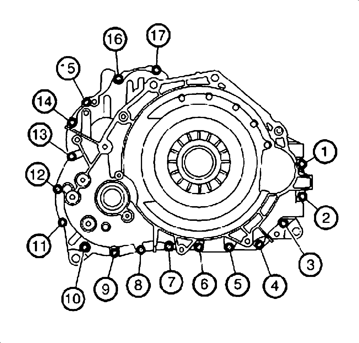
The following repair instructions apply to transaxles that are to be retrofitted using special service-only bolts (P/N 24227740).
Important: Refer to illustration for bolt identification while performing the on-vehicle repair. Bolts located behind the torque converter will not be serviced during an on-vehicle repair.
Important: Replace and tighten one bolt at a time. When a bolt is removed from the transaxle, replace it immediately with the correct service bolt (P/N 24227740) before continuing to the next bolt.
Important: Ensure all service-only bolts are tightened to 28 N·m(21 lb-ft).
- Remove the bolt-labeled number 1. Discard the bolt.
- Install a new service-only bolt (P/N 24227740) to replace bolt number 1.
- Using a torque wrench, tighten the new bolt to 28 N·m (21 lb-ft).
- Continue to remove and replace, one bolt at a time, bolts numbered 2 through 10. Tighten each bolt with a torque wrench immediately after installing. Discard the old bolts.
- Support the transaxle using a transaxle jack.
- Remove the transaxle rear mount through-bolt.
- For All-Wheel Drive (AWD) vehicles:
- For Front-Wheel Drive (FWD) vehicles:
- Remove and replace, one bolt at time, bolts numbered 11 and 12. Tighten each bolt to 28 N·m (21 lb-ft) immediately after installing. Discard the old bolts.
- For All-Wheel Drive (AWD) vehicles:
- For Front-Wheel Drive (FWD) vehicles:
- Remove the two bolts and the transaxle range selector lever cable bracket from the transaxle.
- Remove and replace, one bolt at time, bolts numbered 13 through 15. Tighten each bolt to 28 N·m (21 lb-ft) immediately after installing. Discard the old bolts.
- Install transaxle range selector lever cable bracket to the transaxle and secure with the two bolts.
- Loosen the transaxle front mount through-bolt before lowering the vehicle. This is in preparation for the powertrain rebalance procedure.
- Remove the transaxle support and lower the vehicle.
- Using Fascia Retainer Remover J36346, remove control cable assembly from transaxle range switch lever.
- Disconnect electrical connectors from transaxle range switch.
- Remove transaxle range switch lever nut and lever.
- Remove transaxle range switch bolts and remove switch.
- Remove and replace, one bolt at time, bolts numbered 16 and 17. Tighten each bolt to 28 N·m (21 lb-ft) immediately after installing. Discard the old bolts.
- Align flats on transaxle shift shaft with flats on transaxle range switch and install switch.
- Loosely install transaxle range switch bolts.
- Insert transaxle range switch alignment tool J44810 as shown and rotate switch until tool drops into position. The switch is aligned when the pin on the tool drops into the hole on the transaxle range switch.
- Tighten transaxle range switch bolts to 11 N·m (8 lb-ft).
- Remove alignment tool.
- Install transaxle range switch lever and nut, and tighten nut to 16 N·m (12 lb-ft).
- Connect transaxle range switch electrical connectors.
- Install control cable assembly to transaxle range switch lever and verify proper operation.
- Balance the powertrain mounts by shaking the powertrain vigorously (front-to-rear) and allow the powertrain to settle.
- Raise the vehicle.
- Tighten the transaxle rear mount through-bolt to 110 N·m (81 lb-ft).
- Tighten the transaxle front mount through-bolt to 110 N·m (81 lb-ft).Tighten the transaxle front mount through-bolt to 110 N·m (81 lb-ft).
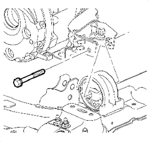
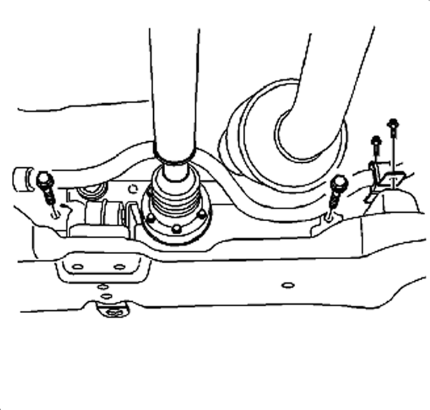
| 7.1. | Remove the two bolts securing the right front stabilizer shaft and insulator to the frame. Move the shaft and insulator in order to gain access to the right-hand bolt securing the steering gear to the frame bracket. |
| 7.2. | Remove the two bolts securing the steering gear to the frame. |
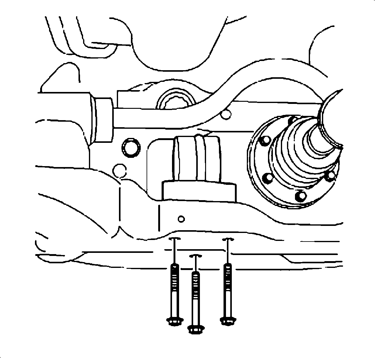
| 7.3. | Remove the three bolts securing the transaxle rear mount to the frame. |
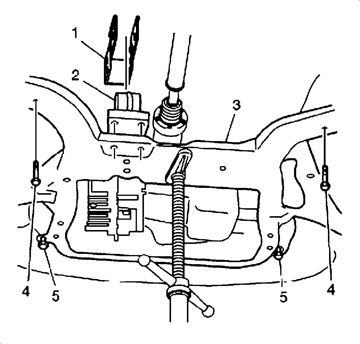
| 7.4. | Support the frame (3) with a frame support jack. |
| 7.5. | Loosen the two front frame bolts (5). Do not remove the bolts. |
| 7.6. | Remove the two rear frame bolts (4). Discard the bolts. |
| 7.7. | Lower the cradle slightly. |
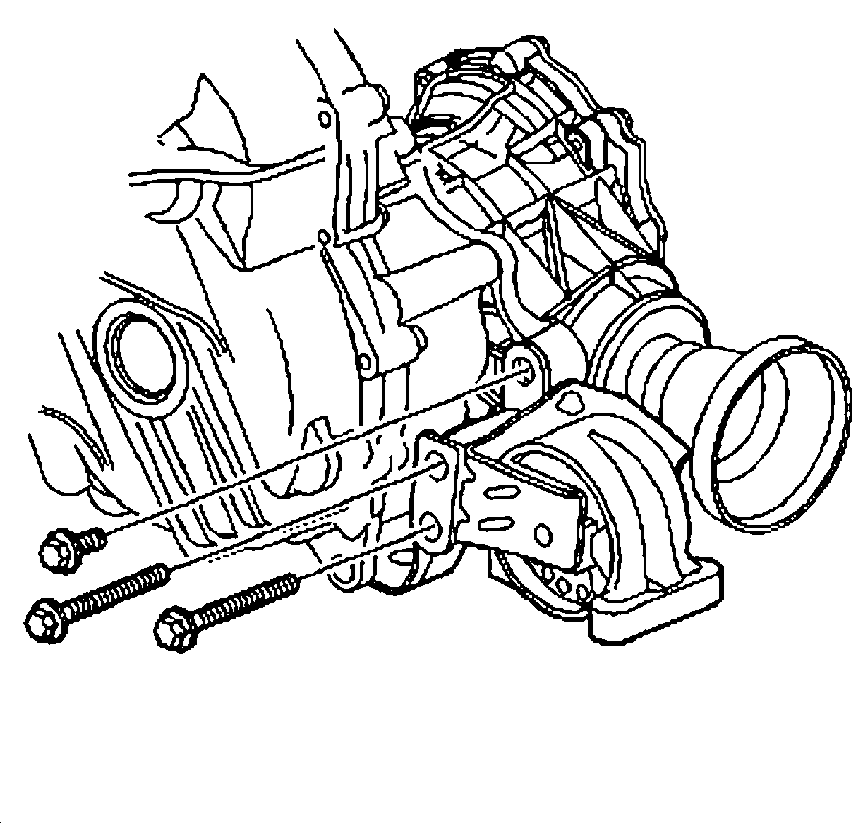
| 7.8. | Remove the three bolts securing the transaxle rear-mounting bracket to the power transfer unit (PTU). |
| 7.9. | Remove the transaxle rear mounting bracket (1) and the transaxle rear mount (2). |
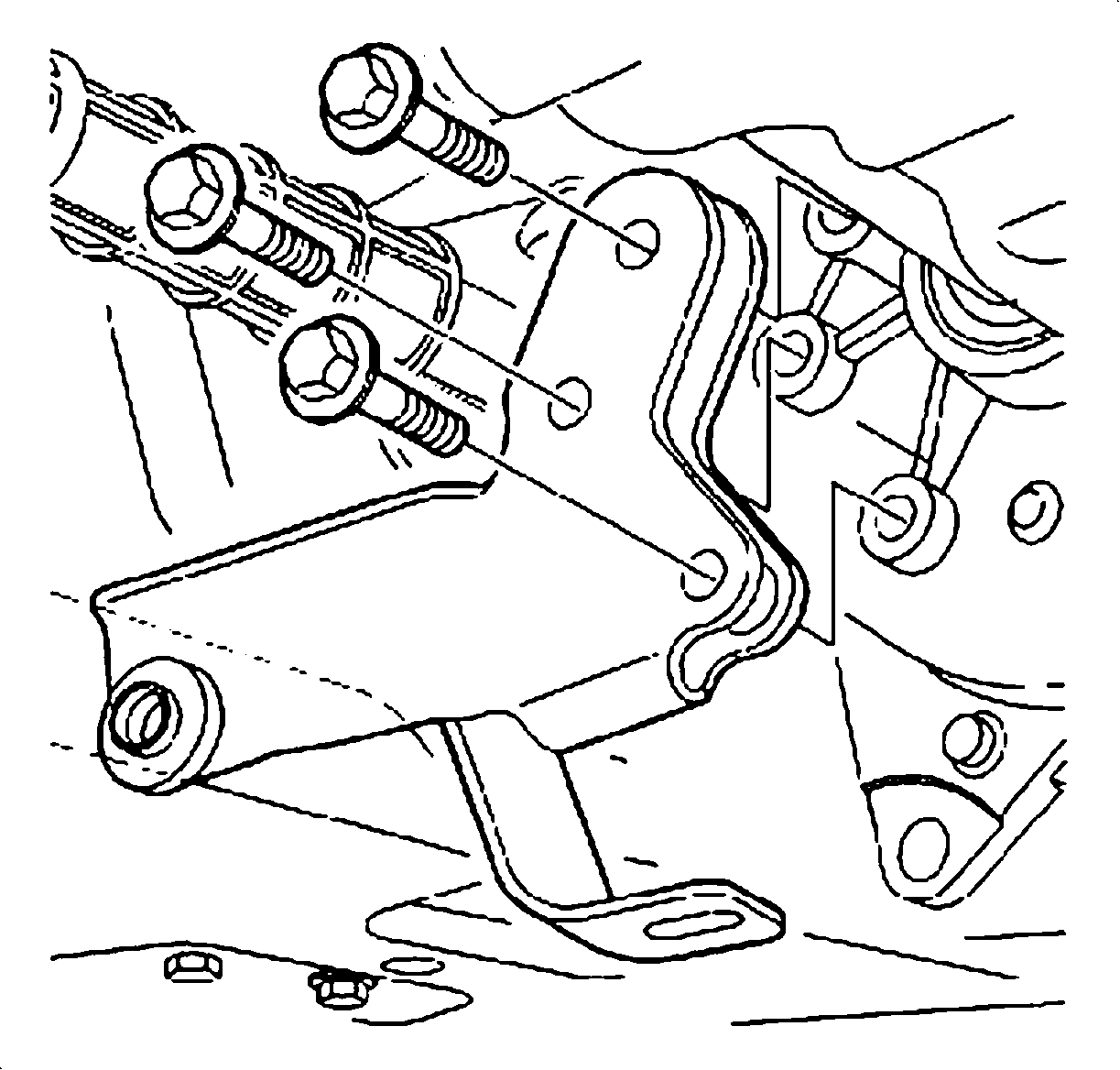
| 8.1. | Remove the three bolts securing the transaxle rear-mounting bracket to the transaxle. |
| 8.2. | Remove the transaxle rear-mounting bracket. |

Important: In order to ensure safety and component stability, it is necessary to reinstall the removed chassis components before proceeding to bolts 13 through 17.

| 10.1. | Install the transaxle rear mounting bracket (1) and transaxle rear mount (2). Do not install bolts at this time. |
| 10.2. | Install the transaxle rear mount through-bolt. Do not tighten the through-bolt at this time. The bolt will be tightened after the procedure has been performed and the powertrain has been rebalanced. |

| 10.3. | Secure the transaxle rear-mounting bracket to the PTU with the three bolts. Tighten the bolts to 110 N·m (81 lb-ft). |

| 10.4. | Install the transaxle rear mount to the frame bolts. Tighten the bolts to 50 N·m (37 lb-ft). |

| 10.5. | Install two new rear frame bolts (4) (P/N 11588565). Tighten the bolts, but do not torque yet. |
| 10.6. | Reposition the frame support to the front of the frame. |
| 10.7. | Remove the two loosened front frame bolts and discard. |
| 10.8. | Install two new front frame bolts (5) (P/N 11588565). Tighten the bolts (5) to 155 N·m (114 lb-ft). |

| 10.9. | Tighten the rear frame bolts to 155 N·m (114 lb-ft). |
| 10.10. | Remove the frame support. |
| 10.11. | Install the steering gear to the frame and secure with the two bolts. Tighten the bolts to 110 N·m (81 lb-ft). |
| 10.12. | Install the right front stabilizer shaft and insulator to the frame and secure with the two bolts. Tighten the bolts to 50 N·m (37 lb-ft). |

| 11.1. | Install the transaxle rear-mounting bracket to the transaxle rear mount and transaxle and secure with the through-bolt and the three bolts. Do not tighten the through-bolt at this time. This bolt will be tightened after the procedure has been performed and the powertrain has been rebalanced. |
| 11.2. | Tighten the three rear mounting bracket-to-transaxle bolts to 55 N·m (41 lb-ft). |

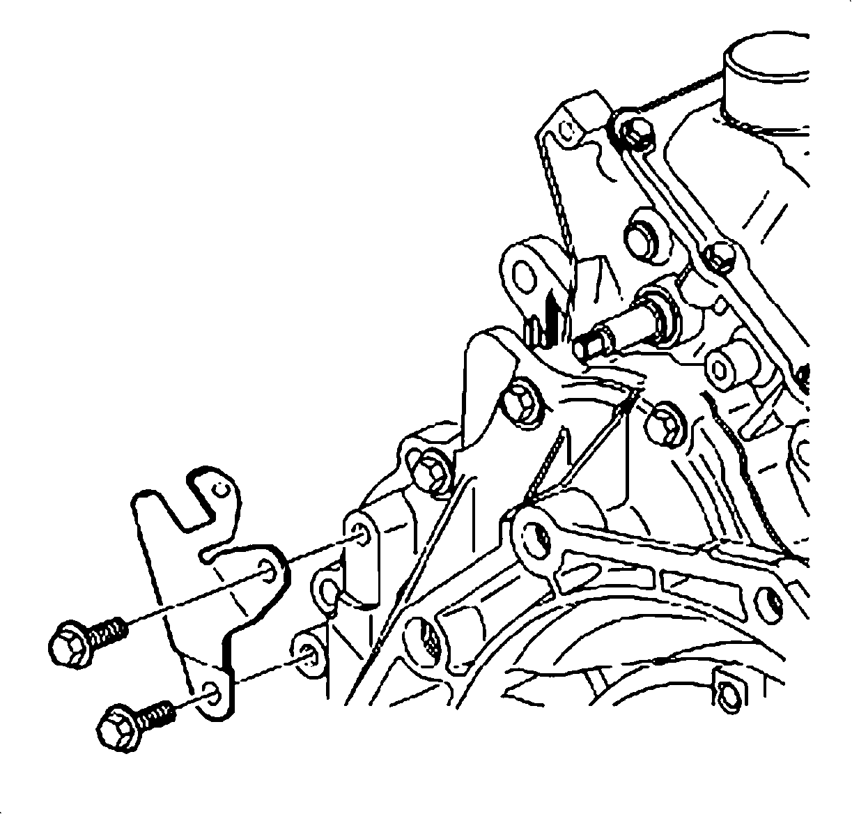


Important: It may be necessary to use a crowfoot in order to remove bolts 16 and 17.
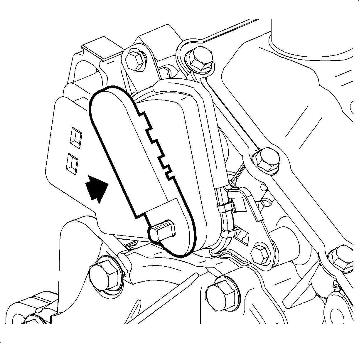
TRANSAXLE REMOVAL AND REPAIR (LEAK DETECTED DURING TRANSAXLE CASE/CONVERTER HOUSING INSPECTION)
- Remove the transaxle from the vehicle. Refer to "Transaxle Replacement" procedure in the 2002-2003 VUE Transaxle service manual.
- Place the transaxle, converter side up, on a repair bench.
- Carefully remove the torque converter.
- Remove all 22 bolts securing the torque converter and differential housing assembly to the transaxle case assembly.
- Using a pry bar, carefully separate the torque converter and differential housing assembly from the transaxle case assembly.
- Remove the torque converter and differential housing assembly.
- Thoroughly clean both flange surfaces using a flat edge scraper. Remove as much old, cured sealant as possible, taking care to not gouge the mating surfaces. Any remaining sealant will bond to the new sealant. Wipe clean to minimize the amount of transaxle oil on the flange surface and blow any residue from the bolt holes.
- Apply a 3 mm (0.12 in) bead of sealant (P/N 22722716) to the mating surface of the transaxle case assembly.
- Carefully install the torque converter and differential housing assembly on the transaxle case assembly.
- Secure the torque converter and differential housing assembly to the transaxle case assembly with the 22 bolts.
- Tighten the bolts to 28 N·m (21 lb-ft) in the sequence shown in illustration.
- Install the transaxle in the vehicle. Refer to "Transaxle Replacement" in the 2002-2003 VUE Transaxle service manual.
- Affix Identification Label to radiator support.
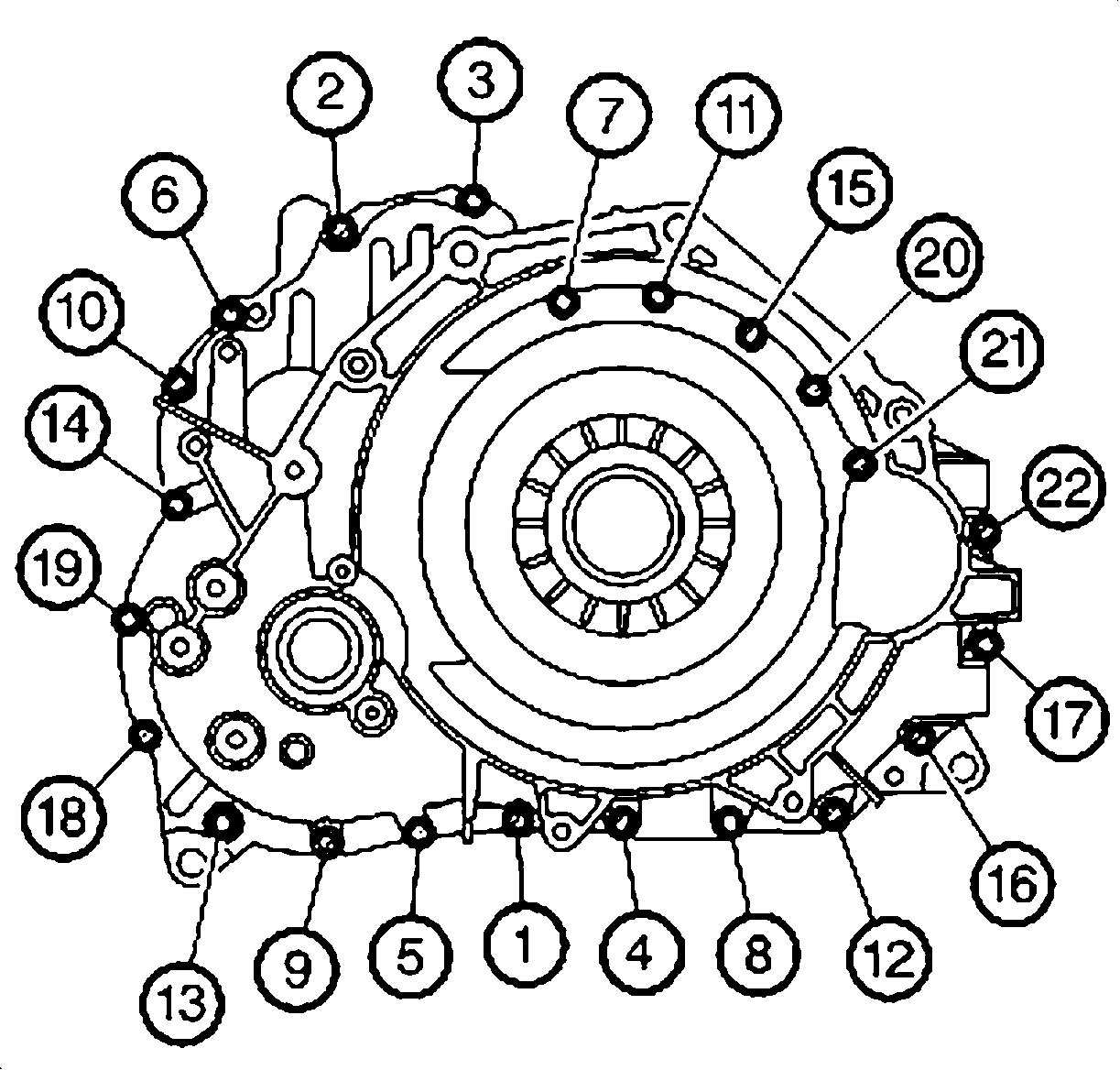
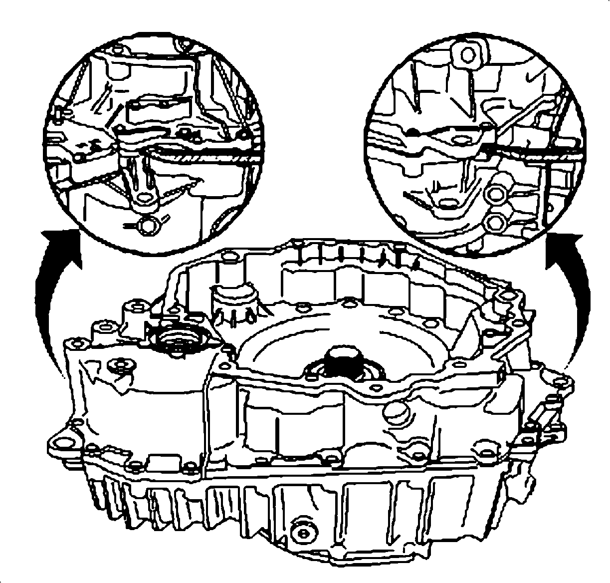
Important: There are two pry points on the torque converter and differential housing assembly.
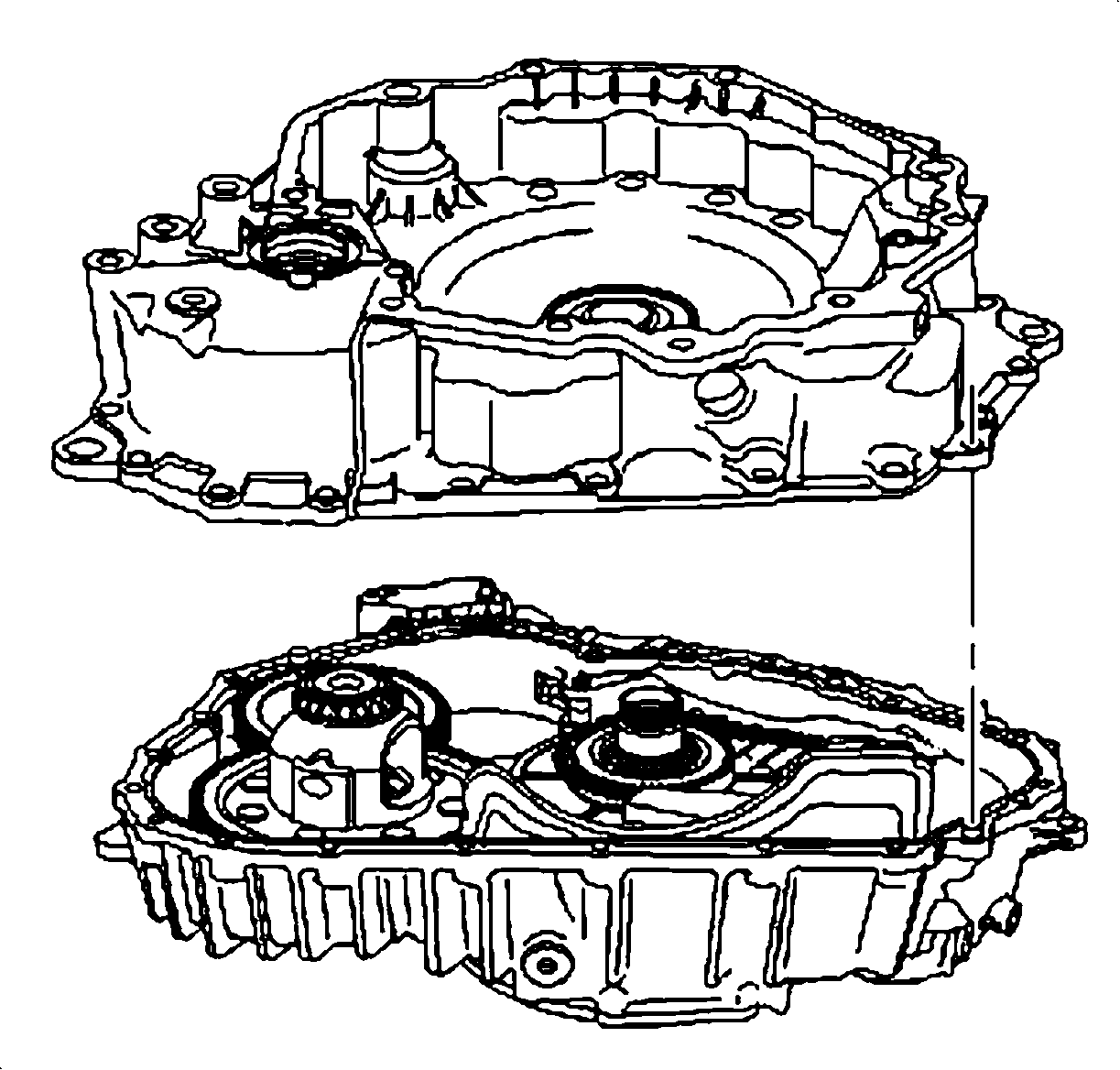
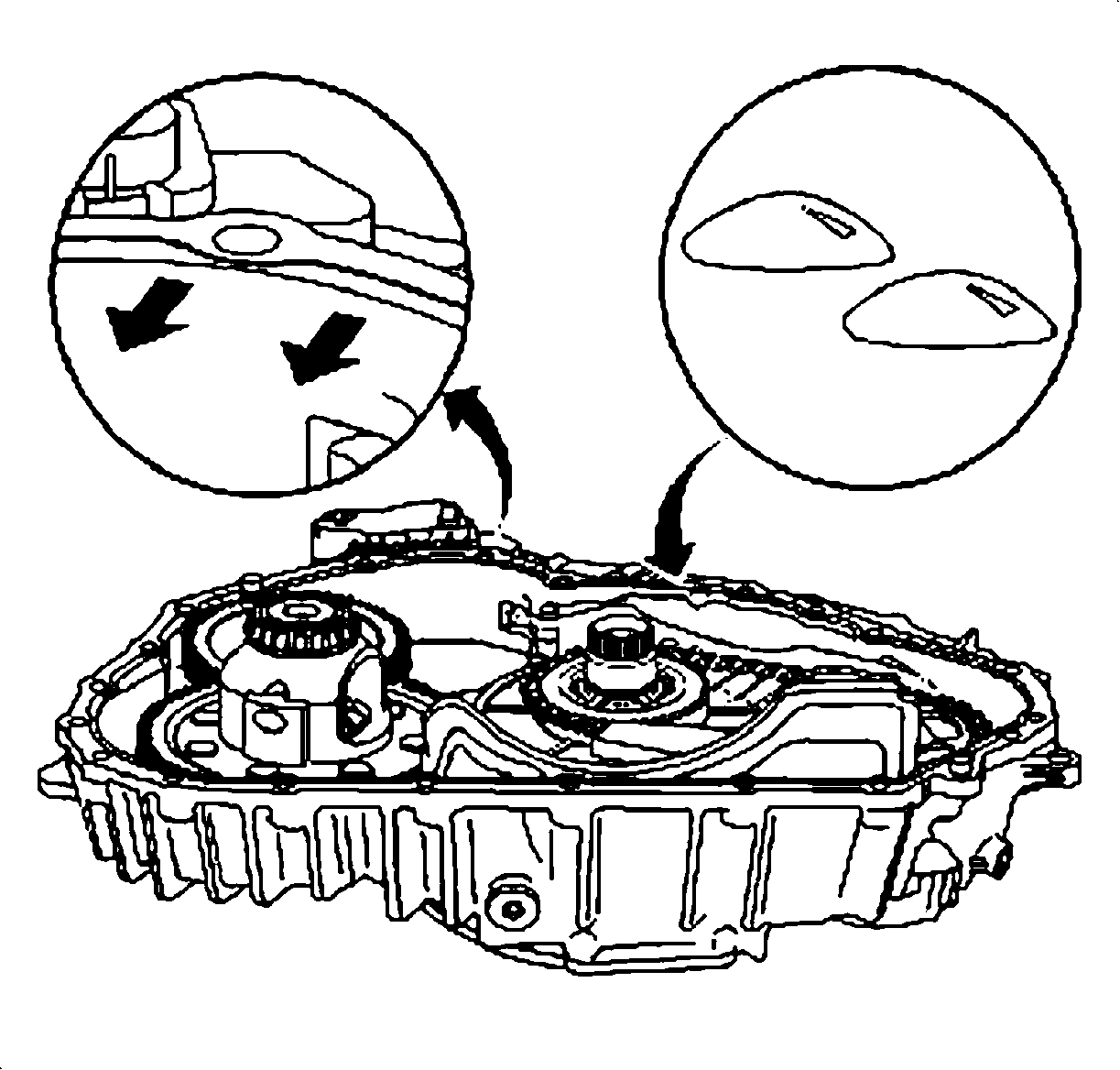
Important: Apply the sealant on the inside mating surface around the bolt holes.


IDENTIFICATION LABEL
Upon completion of this customer satisfaction program, an Identification Label and Clear Protective Cover should be affixed on a clean, dry surface of the radiator core support in an area clearly visible when the hood is raised. Each label provides a space to print in ink (or type) the bulletin number (03-C-05) and the five (5) digit facility code of the retailer performing the bulletin service.
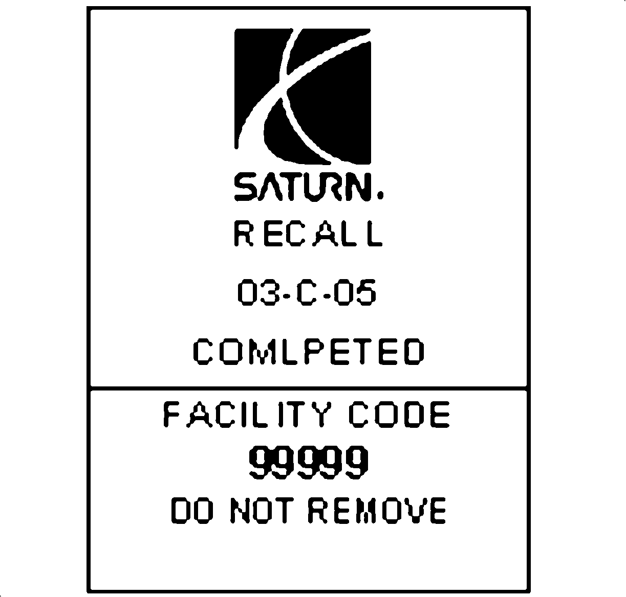
As a reminder, additional labels may be ordered from Saturn publications (1-800-828-2112, prompt 3, Item Number S03 00013A for the Identification Label, and item number S03 00013B for the Clear Protective Cover).
CREDIT
- To receive credit, submit a claim with the information in Table A.
- To receive credit for loaner/rental vehicle costs incurred while owner awaits program repair or other goodwill expenses, submit a claim with the information in Table B.
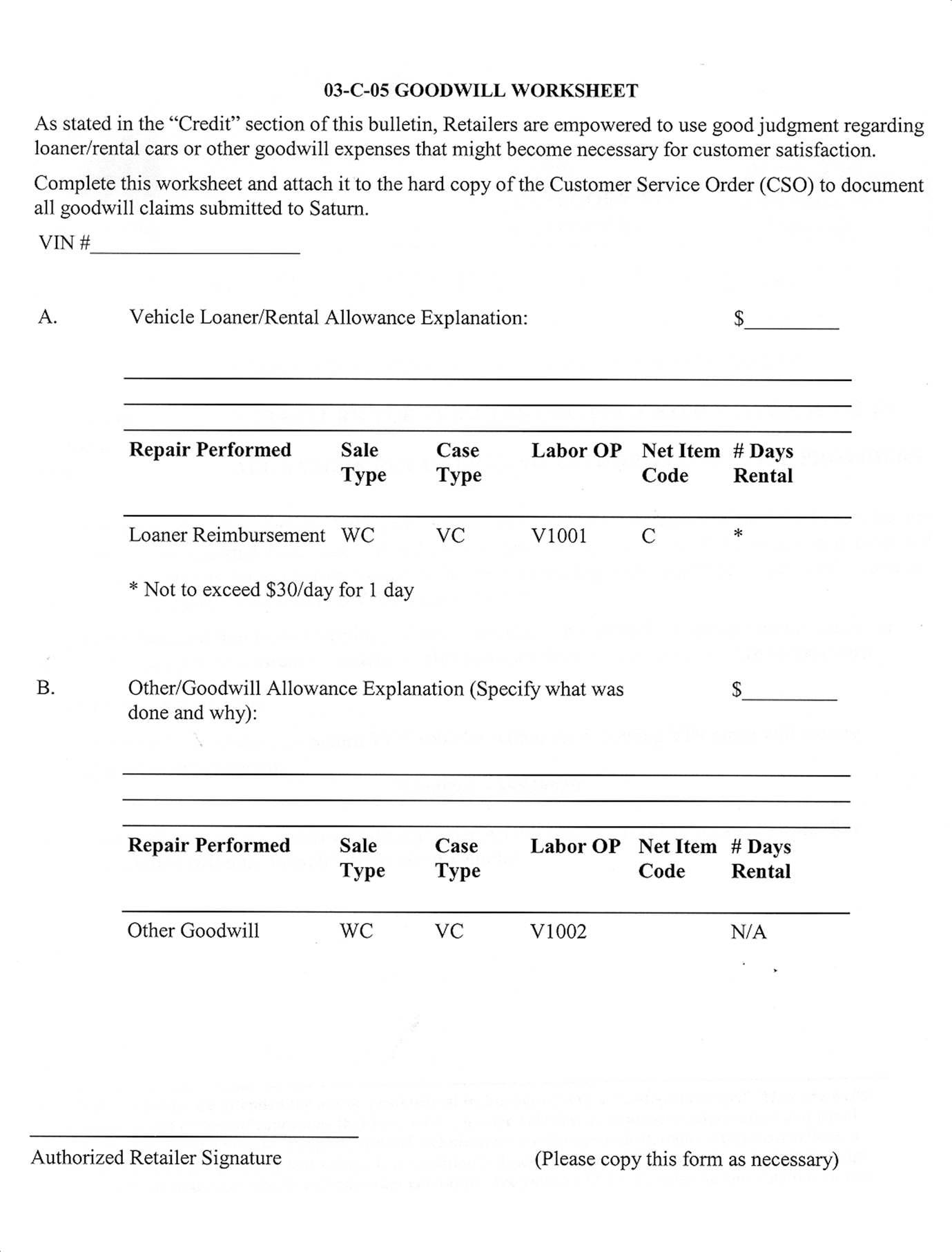
- Retailers are empowered to use good judgment regarding loaner/rental vehicles or any other goodwill expenses deemed necessary. It will not be necessary to call the Saturn Customer Assistance Center for authorization of goodwill. The Goodwill Worksheet (printed towards the back of this bulletin) must be used to document goodwill expenses. The completed Goodwill Worksheet must be attached to the hard copy of the CSO. Retailers are to make sufficient copies of the blank Goodwill Worksheet to document goodwill expenses.
- Check your Saturn SERVICELINE.XL Claim Memorandum daily. Remember to code the claim as a WC sale type, and VC case type. Contact your field representative if you need assistance.
- All labor operations claimed in this bulletin must be submitted on individual (unrelated) CSO lines. Refer to the Customer Service Order Preparation Manual for details on Bulletin Claim Submission.
- Claiming Transaxle Case Sealer Replacement of torque converter & differential housing bolts requires the use of part number 22722716 - Sealer - Trans Case. It will be necessary to sell Sealer to the CSO as "material" using net item code "M". Claims received in the amount of $ 11.27 ($ 8.05 dealer cost plus 40% parts allowance) for this part will be accepted. Claims exceeding the amount of $11.27 will be returned with Return Reason 143 - material/reimbursement > maximum allowed.
*The parts allowance should be the sum total of the current SSPO Retailer net price plus 40% of all parts required for the repair.
**** Administrative allowance
** Net amount must be submitted as a miscellaneous sale...Loaner reimbursement not to exceed $30/day
***Enter number of days vehicle was rented...Not to exceed 1 day
Repair Performed | Parts Allow. | Sale Type | Case Type | Labor Op. | Labor Hrs. | Admin. Hrs.**** |
Remove, install bolts and re-torque -FWD -AWD | * | WC | VC | V0997 | 2.5 3.3 | 0.1 |
Remove transaxle, R&R torque converter & differential housing - FWD - AWD ADD: To align front wheels and adjust front toe (both sides) | * | WC | VC | V0998 | 6.4 6.9 1.1 | 0.1 |
Replace transaxle assembly -FWD -AWD ADD: To align front wheels and adjust front toe (both sides) | * | WC | VC | V0999 | 5.9 6.4 1.1 | 0.1 |
Repair Performed | Sale Type | Case Type | Labor Op. | Net Item Amount | Net Item Code | # Days Rental |
Loaner Reimbursement | WC | VC | V1001 | ** | C | *** |
Other Goodwill | WC | VC | V1002 | ** | R | N/A |
March, 2003
Dear Saturn Owner:
This notice is sent to inform you that Saturn is conducting a voluntary customer satisfaction program that affects certain 2003 Saturn VUE vehicles equipped with VTi transaxles.
Saturn has decided that certain 2003 model year VUE vehicles equipped with VTi transaxles are susceptible to an external fluid leak. This leak is caused by one or more of the torque converter and differential housing to transaxle case assembly fasteners loosening with vehicle use. This leak, when not identified and repaired, may lead to a VTi transaxle failure.
What Saturn will do:
To prevent this condition from occurring, Saturn will replace and properly torque the torque converter housing to transaxle case assembly fasteners.
It will take approximately three to six (3-6) hours to make the repairs, although some additional time may be required for paperwork and processing.
This service will be performed at no charge to you.
What you should do:
Contact your Saturn Retailer as soon as possible to arrange for the repairs.
The enclosed reply card identifies your vehicle and will facilitate completion of the repairs when presented to your Saturn retail facility. If your address has changed, please provide the new information in the space provided. This will assist us in ensuring that all affected vehicles are corrected.
Your Retailer is prepared to perform this service promptly and with minimal inconvenience to you. However, if your vehicle is provided to the Retailer on the agreed service date and the condition is not remedied within a reasonable amount of time, please contact the Saturn Customer Assistance Center at 1-800-553-6000 prompt 3, or for the hearing impaired, 1-800-833-6000. We will assist you and the Retailer in getting your vehicle serviced.
Again, we sincerely regret any inconvenience or concern this situation may cause you. We want you to know that we will do our best, throughout your ownership experience, to ensure that your Saturn provides you many miles of enjoyable driving.
Sincerely,
Saturn Corporation
03-C-05
