Customer Satisfaction - Replacement of Rear Lateral Link Assemblies

| Subject: | REPLACEMENT OF REAR LATERAL LINK ASSEMBLIES |
| Models: | 2002-2004 SATURN VUE VEHICLES |
| Attention: | ALL SATURN RETAILERS AND AUTHORIZED SERVICE PROVIDERS |
The rear lateral link assemblies of certain model year 2002-2004 Saturn VUE vehicles may deform if subjected to a handling maneuver similar to that performed in the National Highway Traffic Safety Administration’s (NHTSA’s) newly implemented Dynamic Maneuvering Test ("Fishhook" Test). Deformation of the rear lateral link could result in the tire and wheel tipping inward until the tire contacts the trailing arm. If the tire were to contact the trailing arm, tire rotation would be inhibited.
To prevent the possibility of this condition occurring, Saturn retailers will replace the rear lateral link assemblies, check and adjust wheel alignment and increase front/rear cold tire inflation pressures. This service will be performed at no cost to the owner.
Vehicles Involved
2002-2004 model year Saturn VUE vehicles within the following VIN range will require participation in this program.
2S800001 - 4S891943
You must verify program involvement through your AS400 system. It is important to note that program claims will only be paid on involved vehicles.
Owner Notification
Owners of all involved vehicles will be re-notified of this customer satisfaction program by Saturn when parts are sufficient. (Refer to the owner letter included in this bulletin.)
Transfer of Customer Satisfaction Program Responsibility
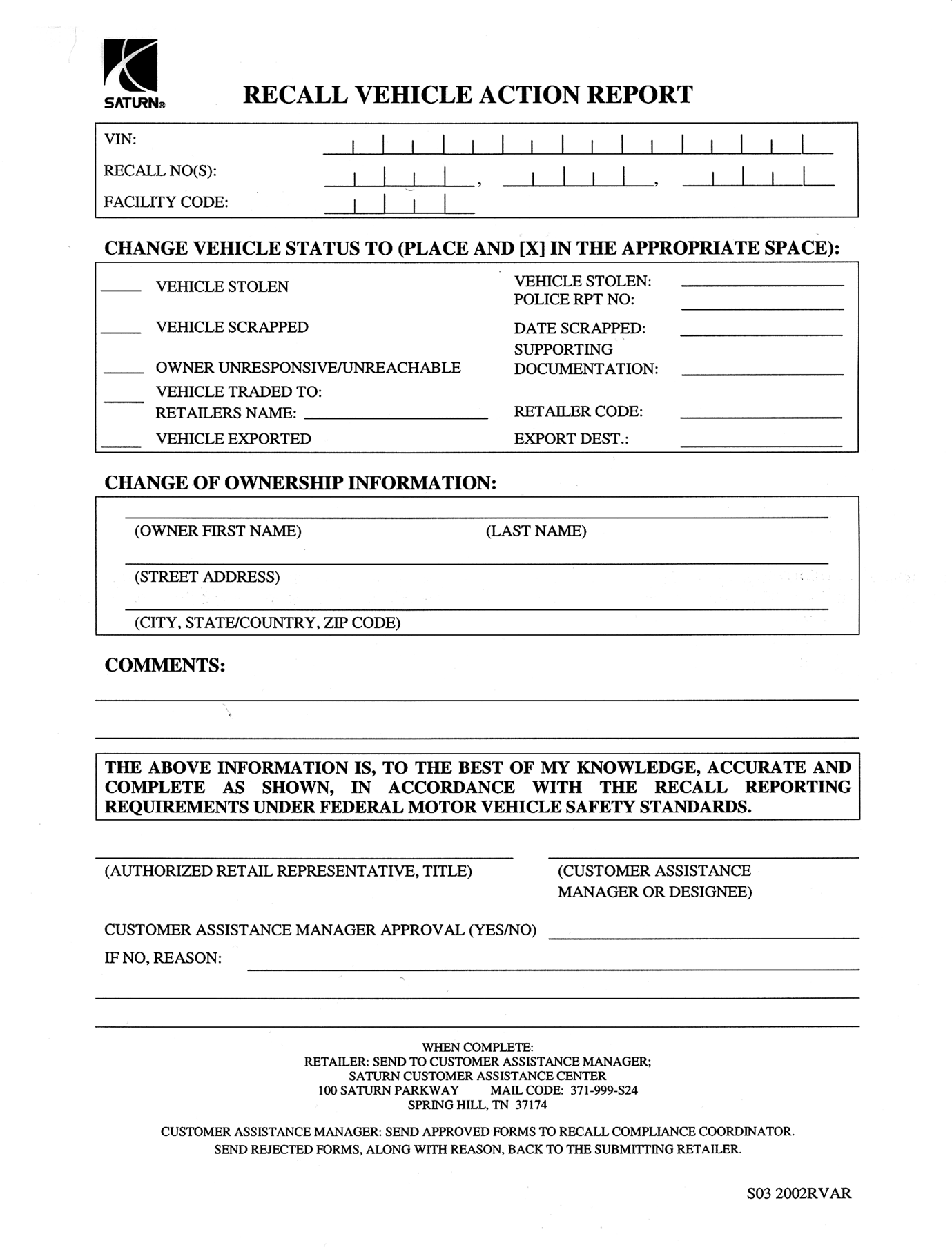
Saturn vehicles that have been sold to you, which may be closer in proximity to another Saturn Retailer, may still appear on your Facility VIN Listing. If you determine that it is more desirable for a vehicle on your Facility VIN Listing to be serviced by another Saturn Retailer, responsibility may be transferred by completing a Recall Vehicle Action Report and submitting it to your Customer Assistance Manager (CAM) at the Saturn Customer Assistance Center.
A copy of the Recall Vehicle Action Report is included for your reference. Additional copies can be ordered from Saturn Publications (1-800-828-2112, prompt 3, Item #S03 2002 RVAR). All changes to program responsibility will be reflected in your next Unfixed VIN Report.
All other changes in vehicle status (e.g., scrapped, stolen, etc.) are to be made in accordance with section 4.4.3 of the Retailer Service Reference Guide, "Notifying Saturn of Vehicle Status Change."
Parts Information
Saturn Service Parts Operations (SSPO) will be allocating and shipping initial recall parts as they become available based on the affected vehicle population at your retail facility. Please do not order these parts. All orders received will be cancelled. Emergency requests processed through the Saturn Customer Assistance Center will be deducted from the following week’s recall parts allocation.
Part Number | Description | Qty/ Vehicle |
|---|---|---|
15249340 | LINK KIT - RR SUSP ADJ | 1 |
Disposition of Replaced Parts
Retailers will scrap all replaced parts in a manner that ensures that they cannot be reused, remanufactured, or otherwise entered into the stream of commerce in the future.
Service Procedure
Removal Procedure
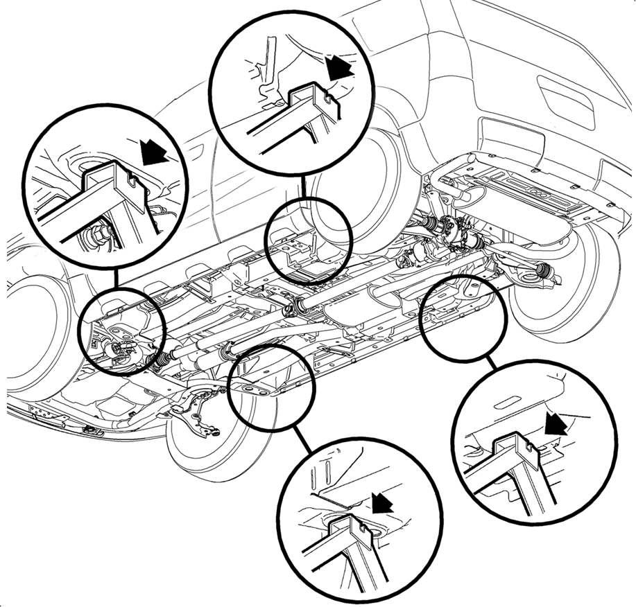
- Raise and support the vehicle. (Refer to illustration.)
- Remove the rear tire and wheel assemblies.
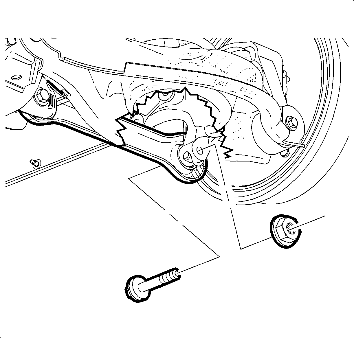
- Remove the outer lateral link (toe link) assembly-to-knuckle nut and bolt. Discard nut and bolt.
- Remove the inner lateral link assembly-to-support assembly nut and bolt. Discard nut and bolt.
- Remove the lateral link assembly from the vehicle and discard.
- Repeat steps 3-5 for lateral link assembly on opposite side of vehicle.
Caution: Make sure vehicle is properly supported and squarely positioned on the hoist. To avoid any vehicle damage, serious personal injury or death when a vehicle is on a hoist, provide additional support for the vehicle at the opposite end from which components are being removed. This will reduce the possibility of the vehicle falling off the hoist.
Caution: To avoid any vehicle damage, serious personal injury or death, always use the jackstands to support the vehicle when lifting the vehicle with a jack.
Notice: Perform the following steps before
starting any vehicle lifting or jacking procedure:
• Remove or secure all of the vehicle's contents in order to avoid any shifting
or any movement that may occur during the vehicle lifting or jacking procedure. • The lifting or jacking equipment weight rating must meet or exceed the
weight of the vehicle and any vehicle contents. • The lifting or jacking equipment must meet the operational standards of
the lifting or jacking equipment's manufacturer. • Perform the vehicle lifting or jacking procedure on a clean, hard, dry,
level surface. • Perform the vehicle lifting or jacking procedure only at the identified
lift points. DO NOT allow the lifting or jacking equipment to contact any other vehicle
components.
Important: Place jackstands ONLY under strong and stable vehicle structures.
| 2.1. | Remove the wheel center cap, if equipped. |
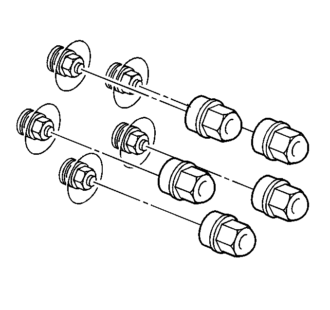
| 2.2. | Remove the wheel nut caps, if equipped. |
| 2.3. | Mark the relationship of the wheel to the hub. |
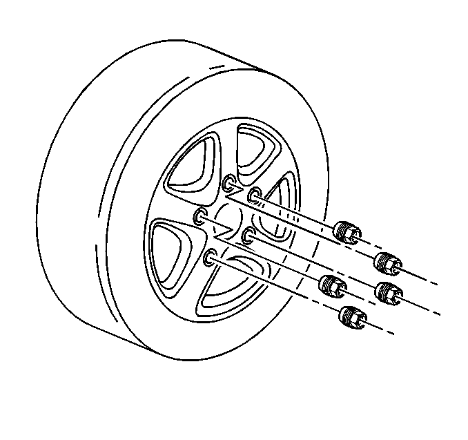
| 2.4. | Remove the wheel nuts. |
| Caution: If penetrating oil gets on the vertical surfaces between the wheel and the rotor or drum it could cause the wheel to work loose as the vehicle is driven, resulting in loss of control and an injury accident. |
| Notice: Removing the wheel may be difficult because of foreign materials or a tight fit between the wheel and the hub/rotor. Slightly tap the tire side wall with a rubber mallet in order to remove the wheel. Failure to follow these instructions may result in damage to the wheel. |
| 2.5. | Remove the tire and wheel assembly from the vehicle. If the tire and wheel assembly is difficult to remove, perform the following steps: |
| 2.5.1. | Install and tighten all wheel nuts on the affected wheel. |
| 2.5.2. | Loosen each wheel nut two turns. |
| 2.5.3. | Lower the vehicle. |
| 2.5.4. | Rock the vehicle from side to side. |
| 2.5.5. | Start the engine. |
| 2.5.6. | Drive the vehicle forward slightly. |
| 2.5.7. | Apply the brakes quickly and firmly. |
| 2.5.8. | Drive the vehicle backward slightly. |
| 2.5.9. | Apply the brakes quickly and firmly. |
| 2.5.10. | Repeat steps 2.5.1-2.5.9, if necessary. |
| 2.6. | Repeat steps 2.1-2.5 for tire and wheel assembly on opposite side of vehicle. |
Installation Procedure
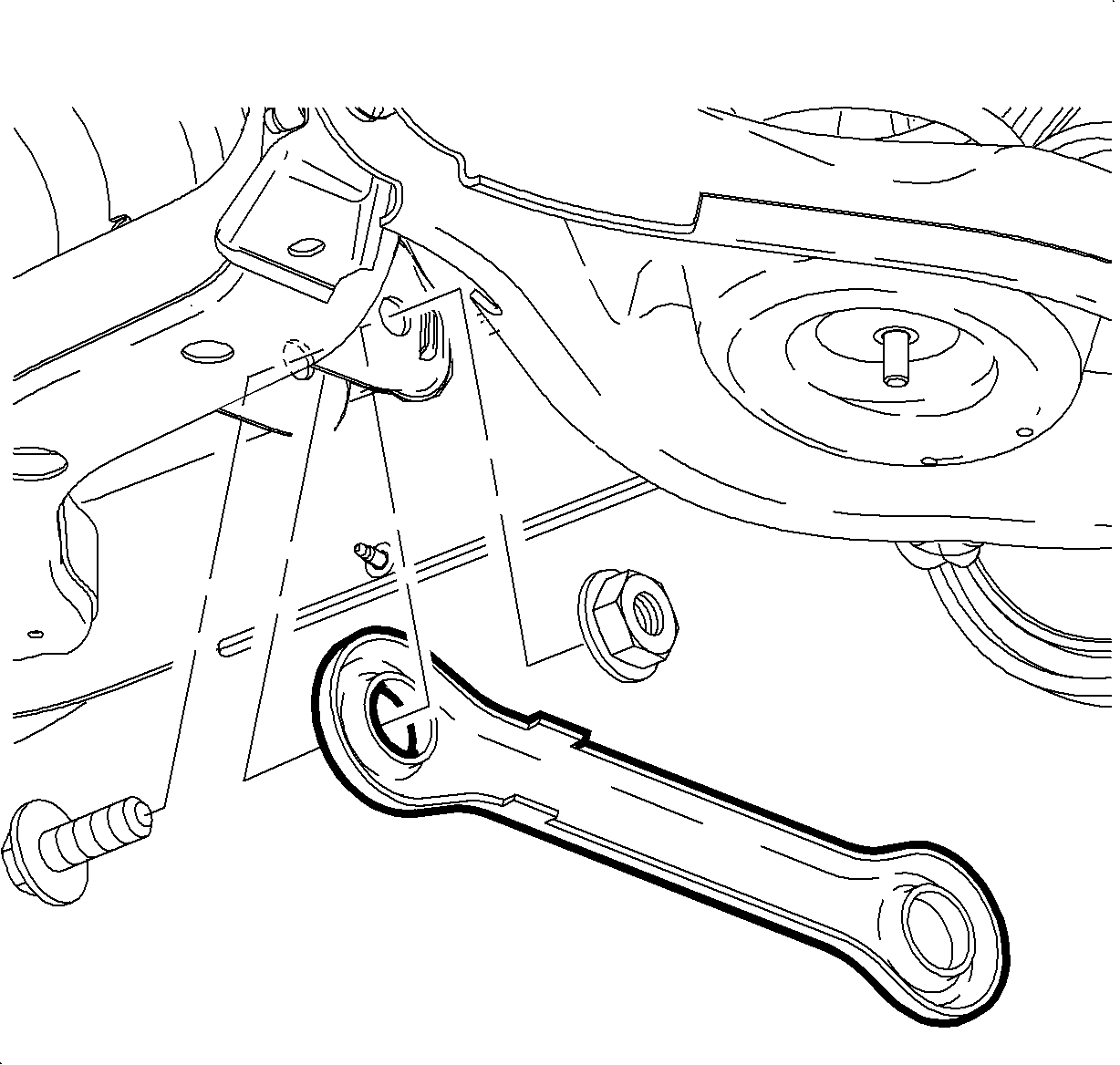
- Position the NEW lateral link assembly (toe link, P/N 15248161) to the knuckle. Install NEW lateral link assembly-to-knuckle bolt (P/N 11518701) and NEW nut (P/N 11516382). Hand tighten only.
- Position lateral link assembly to support assembly. Install NEW lateral link assembly-to-support assembly bolt (P/N 22639398) and NEW cam nut (P/N 11519455). Hand tighten only.
- Tighten the lateral link assembly-to-support assembly bolt and cam nut.
- Tighten lateral link assembly-to-suspension knuckle bolt and nut.
- Repeat steps 1-4 for lateral link assembly on opposite side of vehicle.
- Install rear tire and wheel assemblies.
- Lower the vehicle.
- Perform rear alignment.
- After performing rear alignment, with the steering wheel still locked in the center position, check the front toe and adjust if necessary. Front total toe specification: 0.15° ± 0.15°.
- Open driver’s side (left, front) door and locate Vehicle Certification/Tire label.
- Clean the surface of the door above the Vehicle Certification/Tire label with a clean dry cloth.
- Affix the revised tire pressure label above the Vehicle Certification/Tire label on the left front door. Refer to illustration for label placement.
Notice: Use the correct fastener in the correct location. Replacement fasteners must be the correct part number for that application. Fasteners requiring replacement or fasteners requiring the use of thread locking compound or sealant are identified in the service procedure. Do not use paints, lubricants, or corrosion inhibitors on fasteners or fastener joint surfaces unless specified. These coatings affect fastener torque and joint clamping force and may damage the fastener. Use the correct tightening sequence and specifications when installing fasteners in order to avoid damage to parts and systems.

Important: Toe link flange should face rearward and toe link tabs toward center of vehicle.
Important: Install new bolt with head towards the front of the vehicle.

Important: Install new bolt with the head towards the front of the vehicle and install the new cam nut.
Tighten
Tighten bolt to 145 N·m (107 lb-ft).
Tighten
Tighten bolt and nut to 160 N·m (118 lb-ft).

Caution: Before installing the wheels, remove any buildup of corrosion on the wheel mounting surface and brake drum or disc mounting surface by scraping and wire brushing. Installing wheels with poor metal-to-metal contact at the mounting surfaces can cause wheel nuts to loosen. This can cause a wheel to come off when the vehicle is moving, causing loss of control and possibly personal injury.
Important: Wheel nuts, studs, and mounting surfaces must be clean and dry.
| 6.1. | Remove any corrosion or foreign material from the wheel and the hub mounting surfaces. |
| 6.2. | Clean the threads on the wheel studs and wheel nuts. |
| 6.3. | Install the tire and wheel assembly. Align the locating mark of the wheel to the hub. |
| 6.4. | Install the wheel nuts. |
| Notice: A torque wrench or torque socket J39544 must be used to ensure that wheel nuts are tightened to specification. Never use lubricants or penetrating fluids on wheel stud, nuts, or mounting surfaces, as this can raise the actual torque on the nut without a corresponding torque reading on the torque wrench. Wheel nuts, studs, and mounting surfaces must be clean and dry. Failure to follow these instructions could result in wheel, nut, and/or stud damage. |
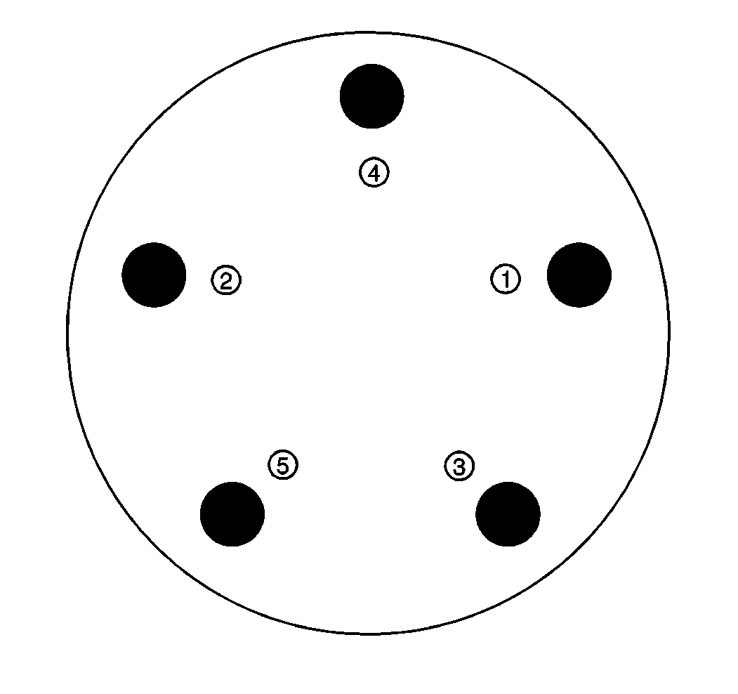
| Notice: Tighten the nuts evenly and alternately in a cross or star pattern, in order to avoid excessive runout. |
| 6.5. | Tighten the wheel nuts in a cross or star pattern. |
Tighten
Tighten nuts to 125 N·m (92 lb-ft).
| 6.6. | Install the wheel center cap, if equipped. |
| 6.7. | Install the wheel nut caps, if equipped. |
Tighten
Tighten nut caps to 5 N·m (44 lb-in).
Important: When measuring alignment angles, it is critical that vehicle bumper heights are within specifications (front: 410 mm ± 25 mm [16.14 in ± 0.98 in]; rear: 435 mm ± 25 mm [17.13 in ± 0.98 in], measured from lower edge of bumper). If not correct, add or remove weight until bumper height is correct.
| 8.1. | Adjust tire pressure to NEW specifications: |
| • | Front Tires: 35 psi (241 kPa) |
| • | Rear Tires: 35 psi (241 kPa) |
| 8.2. | Install the alignment equipment according to the manufacturer's instructions. |
| 8.3. | Jounce the front and the rear bumpers three times prior to checking the wheel alignment. |
| 8.4. | Measure the alignment angles and record the readings. |
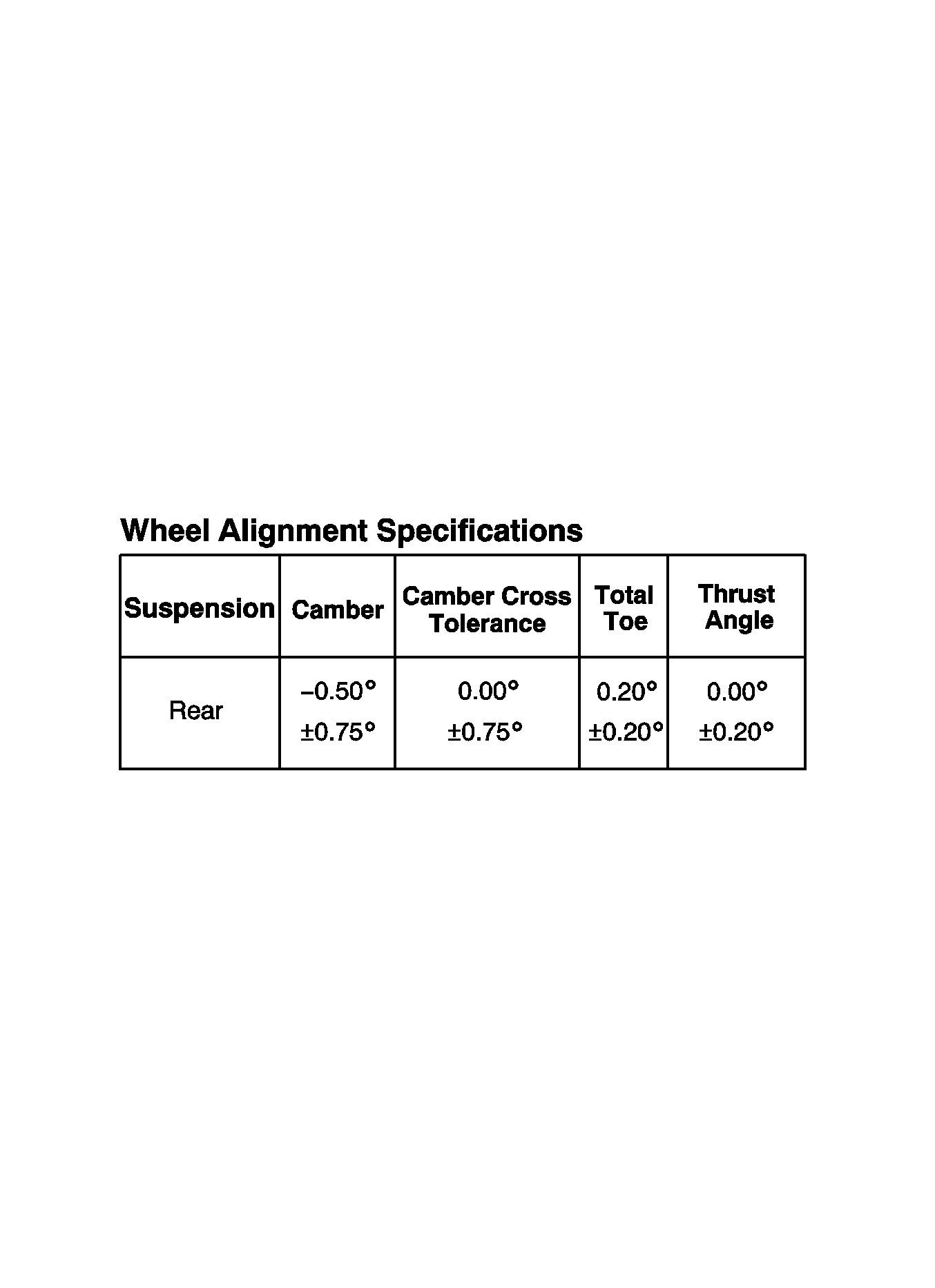
| 8.5. | Adjust alignment angles to vehicle specification, if necessary. Refer to Wheel Alignment Specifications table. Adjust angles in the following order: (1st) rear toe; (2nd) rear camber. |
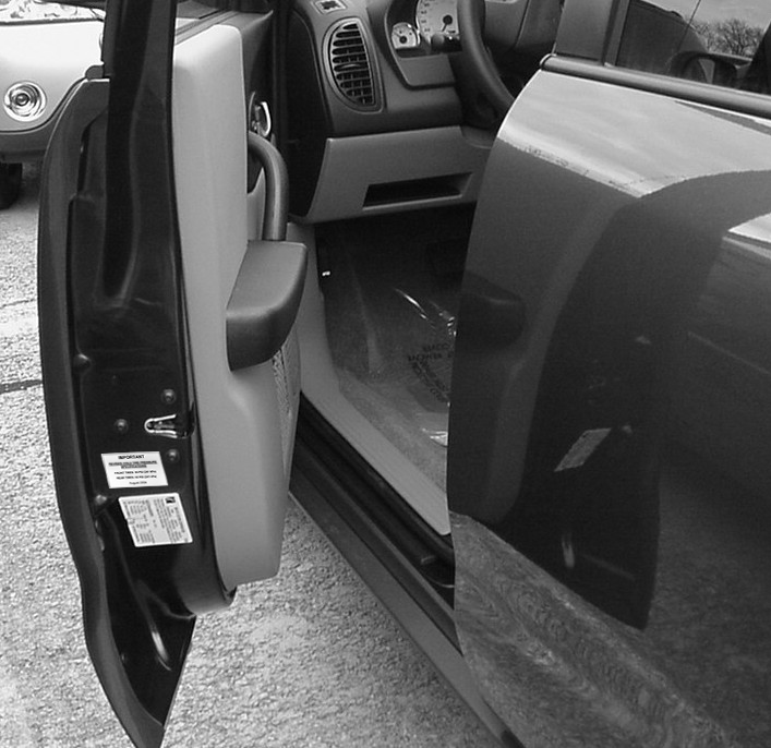
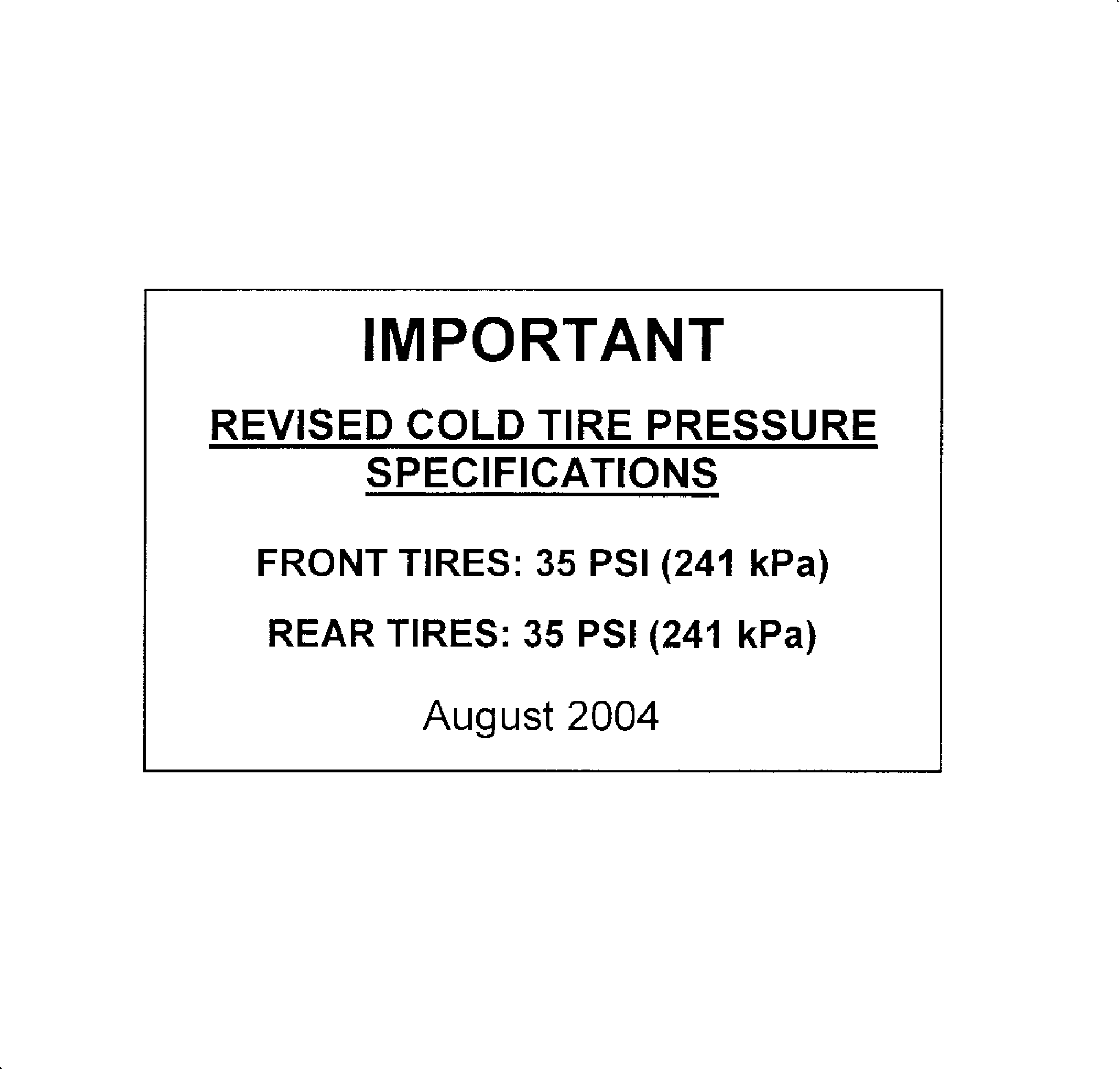
Important: One pack of 250 labels is included in this shipment. Additional packs can be ordered at win.wallace.com/Saturn, item number S03 2004TCL.
Important: To ensure the label adheres to the surface of the door properly, smooth down the edges of the label and then apply pressure to the label for approximately 5 seconds.
Credit
1. To receive credit, submit a claim with the information below:
Repair Performed | Parts Allow | Sale Type | Case Type | Labor Op | Labor Hours* | Admin Hrs**** |
|---|---|---|---|---|---|---|
Replace Rear Lateral Link Assemblies | * | WC | VC | V1217 | 0.6 | 0.1 |
ADD: To check and/or adjust alignment -- FWD | 1.2 | |||||
To check and/or adjust alignment -- AWD | 1.4 | |||||
To adjust front toe -- all vehicles INC: Alignment times include time to set up alignment rack, adjust rear camber and rear toe. | 0.2 |
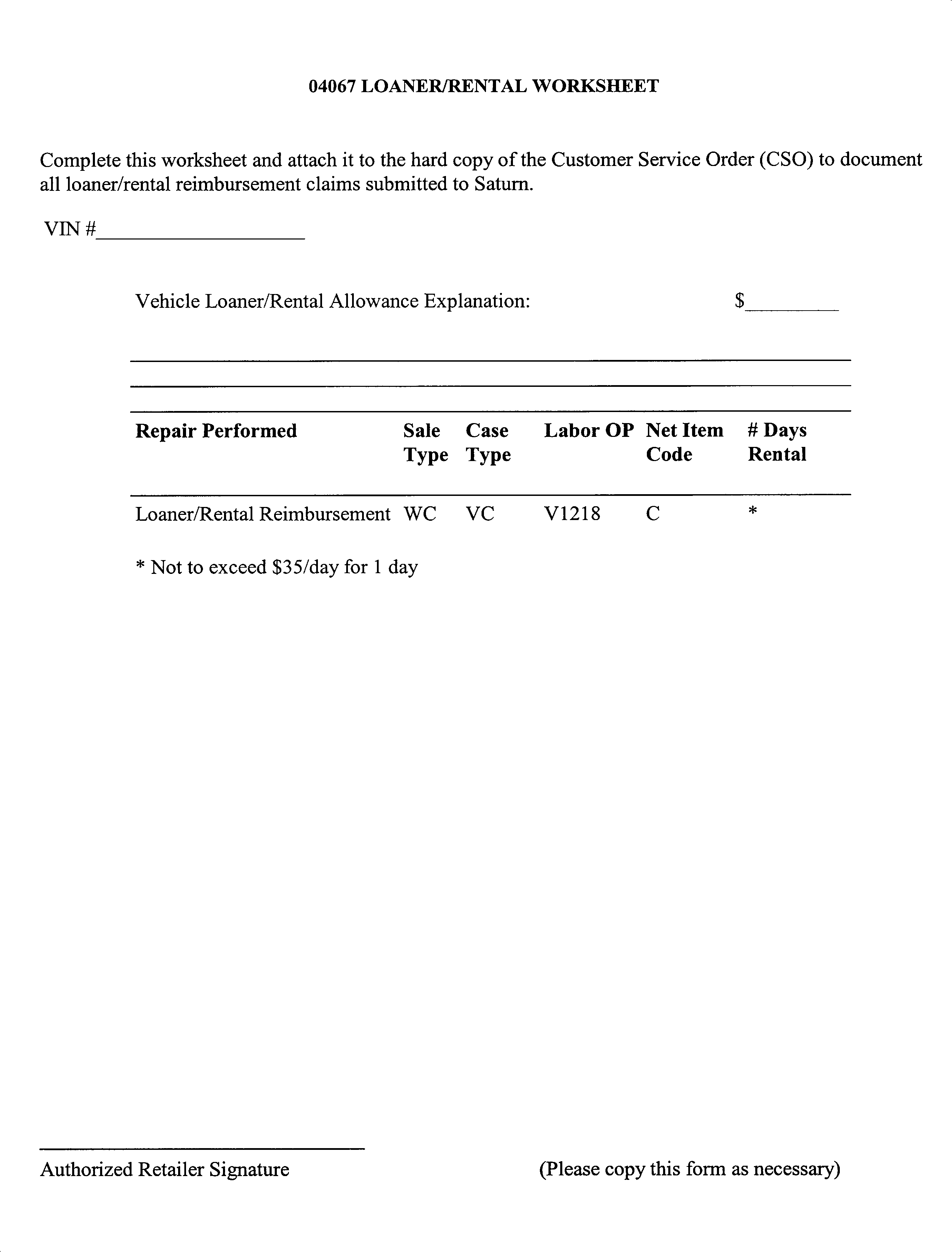
2. To receive credit for loaner/rental vehicle costs incurred while owner awaits program repair or other goodwill expenses, submit a claim with the information below:
Repair Performed | Sale Type | Case Type | Labor Op | Net Item Amount | Net Item Code | # Days Rental |
|---|---|---|---|---|---|---|
Loaner Reimbursement | WC | VC | V1218 | ** | C | *** |
3. Check your Saturn SERVICELINE.XL Claim Memorandum daily. Remember to code the claim as a WC sale type, and VC case type. Contact your field representative if you need assistance.
4. All labor operations claimed in this bulletin must be submitted on individual (unrelated) CSO lines. Refer to the Customer Service Order Preparation Manual for details on Bulletin Claim Submission.
* The parts allowance should be the sum total of the current SSPO Retailer net price plus 40% of all parts required for the repair.
** Net amount must be submitted as a miscellaneous sale...Loaner reimbursement not to exceed $35/day
*** Enter number of days vehicle was rented...Not to exceed 1 day
**** Administrative allowance.
December, 2004
Dear Saturn VUE owner:
In August 2004, Saturn sent letters to current owners of 2002, 2003 and 2004 model year Saturn VUE vehicles to announce a voluntary customer satisfaction program, 04067. In our correspondence we explained that our parts inventory was not sufficient to perform all replacements at that time. We stated we would contact you again once the necessary replacement parts became available.
Today, we are writing to inform you that our parts inventory is now sufficient. Therefore, we urge you to contact your Saturn Retailer as soon as possible to arrange a convenient service appointment. If you have already had the 04067 program repair performed, please disregard this letter.
The rear suspension lateral link assemblies of certain model year 2002-2004 Saturn VUE vehicles may deform if subjected to a handling maneuver similar to that performed in the National Highway Traffic Safety Administration’s (NHTSA’s) newly implemented Dynamic Maneuvering Test ("Fishhook" Test). Deformation of the lateral link could result in the tire and wheel tipping inward until the tire contacts the trailing arm. If the tire were to contact the trailing arm, tire rotation would be inhibited.
What Saturn will do: To prevent this condition from occurring, Saturn retailers will replace the rear lateral link assemblies, check and adjust wheel alignment and increase front/rear cold tire inflation pressures. This repair will be performed for you at no charge.
What you should do: Contact your Saturn Retailer to arrange to have this service performed. Repairs will take about 2 hours although some additional time may be required for paperwork and processing.
The enclosed reply card identifies your vehicle and will facilitate completion of the repairs when presented to your Saturn retail facility. If your address has changed, please provide the new information in the space provided. This will assist us in ensuring that all affected vehicles are corrected.
Your Retailer is prepared to perform this service promptly and with minimal inconvenience to you. However, if your car is provided to the Retailer on the agreed service date and the condition is not remedied on that date, or within a reasonable time, please contact the Saturn Customer Assistance Center at 1-800-972-8876, or for the hearing impaired, 1-800-833-6000. We will assist you and the Retailer in getting your car serviced.
Again, we sincerely regret any inconvenience or concern this situation may cause you. We want you to know that we will do our best, throughout your ownership experience, to ensure that your Saturn provides you many miles of enjoyable and safe driving.
Sincerely,
Saturn
04067
