Circuit Description
The transmission control module (TCM) continuously monitors the system voltage on the Ignition 1 circuits. Lower than normal voltage may be inadequate to operate the transmission control solenoids properly. Improper solenoid operation may cause erratic transmission operation, which may result in internal damage.
When the TCM detects low voltage, DTC P0562 sets. DTC P0562 is a type A DTC.
Conditions for Running The DTC
| • | No ISS DTC P0717. |
| • | Trans. Protection Mode is OFF. |
| • | Transmission input shaft speed is greater than 800 RPM. |
Conditions for Setting The DTC
The TCM detects system voltage is 8.68 volts or less for 20 seconds.
Action Taken When the DTC Sets
| • | The TCM turns the Trans. Protection Mode ON. When the Trans. Protection Mode is ON, the following conditions occur: |
| - | The transmission will operate in 5th gear when the transmission is shifted into D or I range and 2nd gear when shifted into L range. |
| - | The line pressure is at maximum. |
| - | The torque converter clutch (TCC) is disabled. |
| - | The TCM freezes the transmission adaptive functions. |
| • | The TCM requests the engine control module (ECM) to illuminate the malfunction indicator lamp (MIL). |
| • | The TCM records the operating conditions when the Conditions for Setting the DTC are met. The TCM stores this information as Failure Record. |
| • | The TCM stores DTC P0562 in TCM history. |
Conditions for Clearing the MIL/DTC
| • | The TCM turns OFF the MIL request during the third consecutive trip in which the diagnostic test runs and passes. |
| • | A scan tool can clear the MIL/DTC. |
| • | The TCM clears the DTC from TCM history if the vehicle completes 40 warm-up cycles without an emission-related diagnostic fault occurring. |
| • | The TCM cancels the DTC default actions when the ignition switch is OFF long enough in order to power down the TCM. |
Diagnostic Aids
| • | Observe the driver information center (DIC) messaging that would indicate the electrical system requires service. |
| • | Inspect for the following conditions: |
| - | Loose or damaged terminals at the generator |
| - | Loose or worn generator drive belt |
Test Description
The numbers below refer to the step numbers on the diagnostic table.
-
This step tests the charging system voltage with a nominal load.
-
This step obtains the ignition voltage measurement reported by the TCM.
-
This step tests the voltage drop from the battery and ignition voltage input at the TCM.
-
This step tests the voltage drop from the ground terminals of the TCM to the ground terminal of the battery.
Step | Action | Values | Yes | No | ||||||
|---|---|---|---|---|---|---|---|---|---|---|
1 | Did you perform the Diagnostic System Check - Engine Controls? | -- | Go to Step 2 | Go to Diagnostic System Check - Engine Controls in Engine Controls - 3.0L (L81) | ||||||
2 |
Important:
Is the voltage higher than the specified value? | 11 V | Go to Step 3 | Go to Battery Inspection/Test in Engine Electrical | ||||||
3 |
Is the charge indicator light ON? | -- | Go to Diagnostic System Check - Engine Electrical in Engine Electrical | Go to Step 4 | ||||||
Is the voltage within the specified range? | 12.5-14.5 V | Go to Step 5 | Go to Charging System Test in Engine Electrical | |||||||
Is the scan tool Ignition Voltage within the specified range? | 12.5-14.5 V | Go to Intermittent Conditions in Engine Controls - 3.0L (L81) | Go to Step 6 | |||||||
Are the voltage drop measurements less than the specified value? | 0.5 V | Go to Step 10 | Go to Step 7 | |||||||
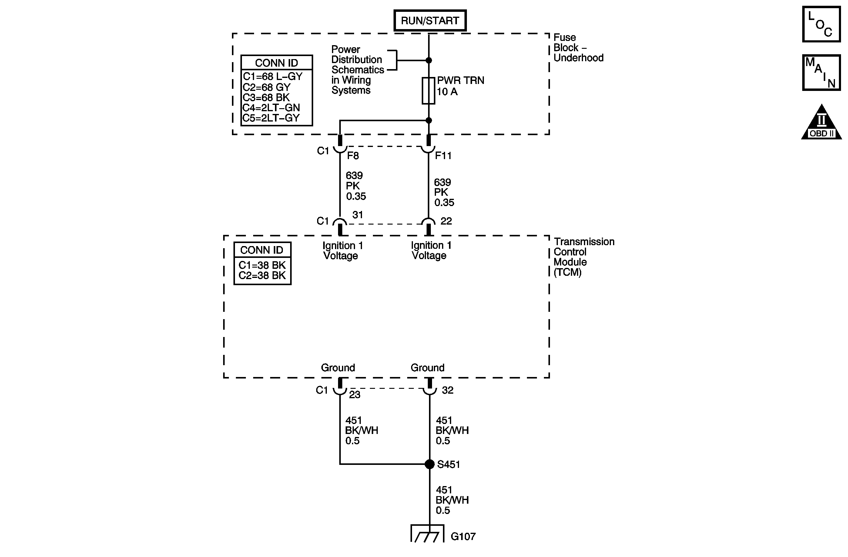
7 | Inspect the 10 amp TRANS1 fuse for an open. Refer to Circuit Protection - Fuses in Wiring Systems. Did you find an open fuse? | -- | Go to Step 8 | Go to Step 9 | ||||||
8 | Repair the short to ground in the ignition voltage circuits (CKTs 639). Refer to Wiring Repairs in Wiring Systems. Is the repair complete? | -- | Go to Step 13 | -- | ||||||
9 | Test the ignition voltage circuits (CKTs 639) for an open or high resistance condition. Refer to Testing for Continuity in Wiring Systems. Did you find and correct a condition? | -- | Go to Step 13 | Go to Step 10 | ||||||
Are both of the voltage drop measurements less than the specified value? | 0.2 V | Go to Step 12 | Go to Step 11 | |||||||
11 | Repair the open or high resistance condition in the TCM ground circuits (CKT 451). Refer to Wiring Repairs in Wiring Systems. Is the repair complete? | -- | Go to Step 13 | -- | ||||||
12 | Replace the TCM. Refer to Transmission Control Module Replacement . Is the action complete? | -- | Go to Step 13 | -- | ||||||
13 | Perform the following procedure in order to verify the repair:
Does the DTC reset? | -- | Go to Step 2 | Go to Step 14 | ||||||
14 | With the scan tool, observe the stored information, capture info and DTC info. Does the scan tool display any DTCs that you have not diagnosed? | -- | Go to Diagnostic Trouble Code (DTC) List in Engine Controls - 3.0L (L81) | System OK |
