System Description
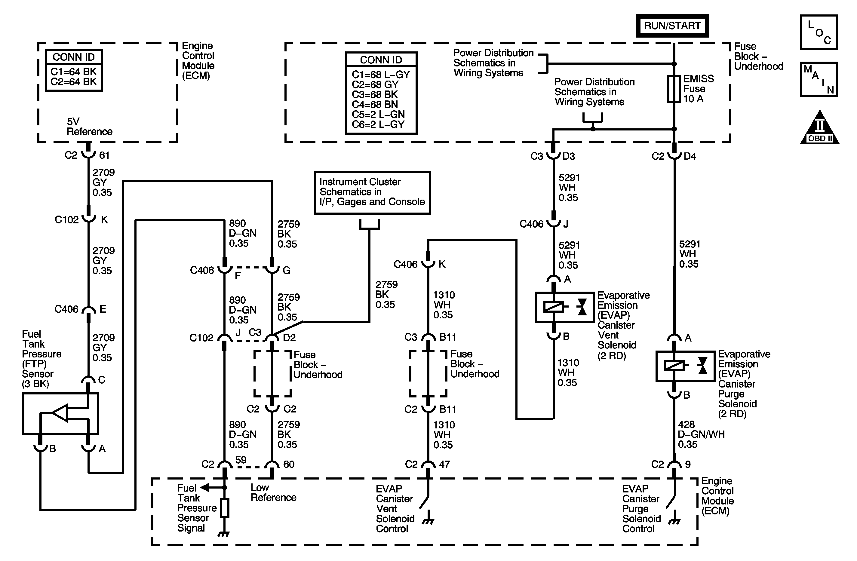
The evaporative emission (EVAP) system is used to store fuel vapors to reduce the amount of unburned fuel from escaping into the atmosphere. The EVAP system consists of the EVAP canister, the fuel tank pressure (FTP) sensor, the EVAP lines and hoses, the EVAP purge solenoid which is normally closed, the EVAP service port, the EVAP vent solenoid which is normally open, the fuel tank, and the engine control module (ECM). The ECM monitors the EVAP system for circuit faults in the FTP sensor, the EVAP purge solenoid and the EVAP vent solenoid circuits. The ECM also monitors the EVAP system for small and large leaks. During the DTC P0440 diagnostic, the ECM monitors the FTP sensor for an atmospheric pressure reading when all of the DTC parameters have been met with the engine running. The ECM will then command the EVAP vent solenoid ON which is a closed valve, and command the EVAP purge solenoid to a fixed duty cycle. The ECM will let the pressure drop in the fuel tank for a certain length of time after which it will turn OFF the EVAP purge solenoid. DTC P0440 sets when a certain vacuum in the fuel tank could not be achieved due to a large leak or a lack of vacuum source.
Conditions for Running the DTC
| • | DTCs P0105, P0107, P0108, P0112, P0113, P0117, P0118, P0122, P0123, P0125, P0131, P0132, P0133, P0134, P0135, P0452, P0453, P0502, P0601, P0602, P1621 are not set. |
| • | The EVAP vent solenoid is commanded ON, closed. |
| • | The EVAP purge solenoid is commanded to a fixed duty cycle. |
| • | The engine is running. |
| • | The fuel tank level is between 15-85 percent. |
| • | The barometric pressure (BARO) is more than 75 kPa. |
| • | The engine coolant temperature (ECT) and the intake air temperature (IAT) at engine startup are between 4-30°C (39-86°F). |
| • | The ECT and the IAT are within 8°C (15°F) of each other. |
| • | The throttle position (TP) angle is between 7-35 percent. |
| • | The vehicle speed is less than 113 km/h (70 mph). |
| • | The DTC P0440 diagnostic runs once per ignition cycle after the above conditions have been met. |
Conditions For Setting the DTC
| • | If the FTP voltage is less than 3 volts during the DTC P0440 diagnostic test indicating a vacuum cannot be pulled on the EVAP system, DTC P0440 will set. |
| • | The above condition exists for longer than 6 minutes and 40 seconds. |
Action Taken When the DTC Sets
| • | The control module illuminates the malfunction indicator lamp (MIL) when the diagnostic runs and fails. |
| • | The control module records the operating conditions at the time the diagnostic fails. The control module stores this information in the Freeze Frame/Failure Records. |
Conditions for Clearing the MIL/DTC
| • | The control module turns OFF the malfunction indicator lamp (MIL) after 3 consecutive ignition cycles that the diagnostic runs and does not fail. |
| • | A current DTC, Last Test Failed, clears when the diagnostic runs and passes. |
| • | A history DTC clears after 40 consecutive warm-up cycles, if no failures are reported by this or any other emission related diagnostic. |
| • | Clear the MIL and the DTC with a scan tool. |
Diagnostic Aids
| • | The ECM uses the FTP sensor to detect the amount of vacuum pulled on the EVAP system during the leak diagnostic tests. Ensure that the fuel pressure sensor is not skewed by verifying the FTP sensor on the scan tool is between 1.30-1.70 volts with the ignition ON and the fuel cap removed. |
| • | If this test fails, a warm test will be performed and can only pass, not fail, a diagnostic test. The purpose of this test is to keep the malfunction indicator lamp (MIL) OFF during the initial test if the customer starts the vehicle with the fuel cap off. |
| • | Visually inspect for a large leak in the EVAP system. Locate the leak with the J 41413-200 (J 41413-100) Evaporative Emissions System Tester (EEST). |
| • | The following are possible causes of a large leak: |
| - | The fuel cap is missing, is incorrectly installed or is leaking. |
| - | The EVAP vent solenoid is stuck open. |
| - | The EVAP purge solenoid is stuck closed or is blocked. |
| - | The EVAP vent hose is loose or is damaged. |
| - | The EVAP canister is leaking. |
| - | The fuel sender assembly O-ring is leaking. |
| - | The fuel tank or filler neck is leaking. |
| - | A condition may exist where a leak in the EVAP system only exists under a vacuum condition. By using the scan tool Purge/Seal function to create a vacuum, seal the system and observe the fuel tank pressure (FTP) parameter for vacuum decay, this type of leak may be detected. |
Step | Action | Values | Yes | No | ||||||||||
|---|---|---|---|---|---|---|---|---|---|---|---|---|---|---|
Schematic Reference: Engine Controls Schematics Evaporative Emissions Hose Routing Diagram Connect End View Reference: Engine Control Module Connector End Views or Engine Controls Connector End Views | ||||||||||||||
1 | Did you perform the Diagnostic System Check-Engine Controls? | -- | Go to Step 2 | |||||||||||
2 |
Did you find and correct the condition? | -- | Go to Step 34 | Go to Step 3 | ||||||||||
3 |
Do you hear or feel a clicking from the EVAP purge solenoid when it is commanded to 50 percent? | -- | Go to Step 4 | Go to Step 5 | ||||||||||
4 | Command the EVAP vent solenoid ON and OFF with the scan tool. Do you hear or feel a click as the EVAP vent solenoid is commanded ON and OFF? | -- | Go to Step 9 | Go to Step 7 | ||||||||||
5 |
Does the test lamp illuminate? | -- | Go to Step 6 | Go to Step 25 | ||||||||||
6 |
Does the test lamp illuminate or pulsate when the EVAP purge solenoid is commanded to 50 percent and turn OFF when the EVAP purge solenoid is commanded to 0 percent? | -- | Go to Step 20 | Go to Step 18 | ||||||||||
7 |
Does the test lamp illuminate? | -- | Go to Step 8 | Go to Step 26 | ||||||||||
8 |
Does the test lamp illuminate? | -- | Go to Step 21 | Go to Step 19 | ||||||||||
9 |
Important: Ensure that the vehicle underbody temperature is similar to the ambient temperature and allow the surrounding air to stabilize before starting the diagnostic procedure. System flow will be less with higher temperatures.
Did you locate and repair a leak source? | -- | Go to Step 34 | Go to Step 10 | ||||||||||
10 |
Did you locate and repair a leak source? | -- | Go to Step 34 | Go to Step 11 | ||||||||||
11 |
Is the scan tool Fuel Tank Pressure Sensor parameter within the specified value? | 1.30-1.70 V | Go to Step 12 | Go to Step 22 | ||||||||||
12 |
Is the Fuel Tank Pressure Sensor parameter less than the second specified value? | 10 in H2O 0.5 V | Go to Step 13 | Go to Step 22 | ||||||||||
13 |
Is the Fuel Tank Pressure Sensor parameter within the specified value? | 1.30-1.70 V | Go to Diagnostic Aids | Go to Step 14 | ||||||||||
14 | Disconnect the EVAP purge vacuum source from the EVAP purge solenoid. Is the Fuel Tank Pressure Sensor parameter within the specified value? | 1.30-1.70 V | Go to Step 24 | Go to Step 15 | ||||||||||
15 | Disconnect the EVAP purge pipe from the EVAP purge solenoid. Is the Fuel Tank Pressure Sensor parameter within the specified value? | 1.30-1.70 V | Go to Step 29 | Go to Step 16 | ||||||||||
16 | Disconnect the EVAP purge pipe at the EVAP canister. Is the Fuel Tank Pressure Sensor parameter within the specified value? | 1.30-1.70 V | Go to Step 27 | Go to Step 17 | ||||||||||
17 | Disconnect the EVAP vapor pipe at the EVAP canister. Is the Fuel Tank Pressure Sensor parameter within the specified value? | 1.30-1.70 V | Go to Step 31 | Go to Step 28 | ||||||||||
18 | Test the control circuit of the EVAP purge solenoid for an open or for a short to voltage. Refer to Circuit Testing and Wiring Repairs in Wiring Systems. Did you find and correct the condition? | -- | Go to Step 34 | Go to Step 23 | ||||||||||
19 | Test the control circuit of the EVAP vent solenoid for an open or for a short to voltage. Refer to Circuit Testing and Wiring Repairs in Wiring Systems. Did you find and correct the condition? | -- | Go to Step 34 | Go to Step 23 | ||||||||||
20 | Test for an intermittent and for a poor connection at the EVAP canister purge solenoid. Refer to Testing for Intermittent Conditions and Poor Connections and Connector Repairs in Wiring Systems. Did you find and correct the condition? | -- | Go to Step 34 | Go to Step 29 | ||||||||||
21 | Test for an intermittent and for a poor connection at the EVAP vent solenoid. Refer to Testing for Intermittent Conditions and Poor Connections and Connector Repairs in Wiring Systems. Did you find and correct the condition? | -- | Go to Step 34 | Go to Step 30 | ||||||||||
22 | Test for an intermittent and for a poor connection at the fuel tank pressure (FTP) sensor. Refer to Testing for Intermittent Conditions and Poor Connections and Connector Repairs in Wiring Systems. Did you find and correct the condition? | -- | Go to Step 34 | Go to Step 32 | ||||||||||
23 | Test for an intermittent and for a poor connection at the control module. Refer to Testing for Intermittent Conditions and Poor Connections and Connector Repairs in Wiring Systems. Did you find and correct the condition? | -- | Go to Step 34 | Go to Step 33 | ||||||||||
24 | Repair the pinched or obstructed EVAP purge solenoid vacuum source. Did you complete the repair? | -- | Go to Step 34 | -- | ||||||||||
25 |
Did you complete the repair? | -- | Go to Step 34 | -- | ||||||||||
26 | Repair the open or short to ground in the ignition 1 voltage circuit of the EVAP vent solenoid. Refer to Wiring Repairs in Wiring Systems. Replace the fuse as necessary. Did you complete the repair? | -- | Go to Step 34 | -- | ||||||||||
27 | Repair the restriction in the EVAP purge pipe. Did you complete the repair? | -- | Go to Step 34 | -- | ||||||||||
28 | Repair the restriction in the EVAP vapor pipe. Did you complete the repair? | -- | Go to Step 34 | -- | ||||||||||
29 | Replace the EVAP purge solenoid. Refer to Evaporative Emission Canister Purge Solenoid Replacement . Did you complete the replacement? | -- | Go to Step 34 | -- | ||||||||||
30 | Replace the EVAP vent solenoid. Refer to Evaporative Emission Canister Vent Solenoid Replacement . Did you complete the replacement? | -- | Go to Step 34 | -- | ||||||||||
31 | Replace the EVAP canister. Refer to Evaporative Emission Canister Replacement . Did you complete the replacement? | -- | Go to Step 34 | -- | ||||||||||
32 | Replace the FTP sensor. Refer to Fuel Tank Pressure Sensor Replacement . Did you complete the replacement? | -- | Go to Step 34 | -- | ||||||||||
33 | Replace the control module. Refer to Engine Control Module Replacement . Did you complete the replacement? | -- | Go to Step 34 | -- | ||||||||||
34 |
Important: Larger volume fuel tanks and/or those with lower fuel levels may require several minutes for the floating indicator to stabilize.
Is the floating indicator below the red flag? | -- | Go to Step 35 | Go to Step 2 | ||||||||||
35 | Observe the Capture Info with a scan tool. Are there any DTCs that have not been diagnosed? | -- | System OK | |||||||||||
