For 1990-2009 cars only
Tools Required
J 39194-C O2 Sensor Remover Tool
Removal Procedure
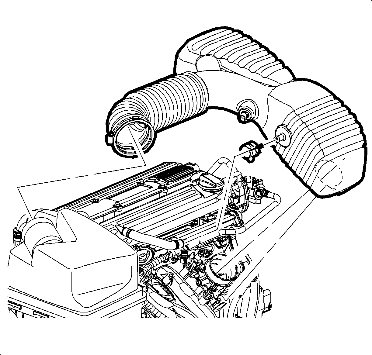
- Disconnect the intake air temperature (IAT) sensor connector.
- Loosen the clap at the air cleaner assembly.
- Remove the push-pin attachment from the outlet resonator/duct assembly to support the bracket.
- Loosen the clamp at the throttle body assembly.
- Disconnect the PCV fresh air vent hose at the cam cover.
- Remove the outlet resonator/duct assembly.
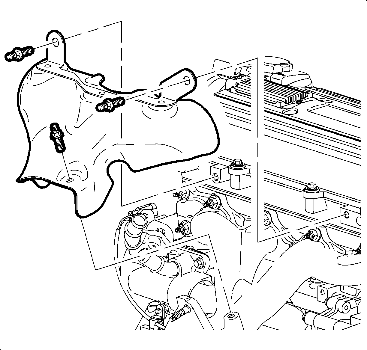
- Remove the exhaust manifold heat shield bolts.
- Remove the exhaust manifold heat shield.
- Disconnect the front and rear O2 sensor connectors. Remove the sensor if the exhaust manifold is being replaced using J 39194-C .
- Raise the vehicle. Refer to Lifting and Jacking the Vehicle in General Information.
- Remove the exhaust manifold pipe to manifold nuts.
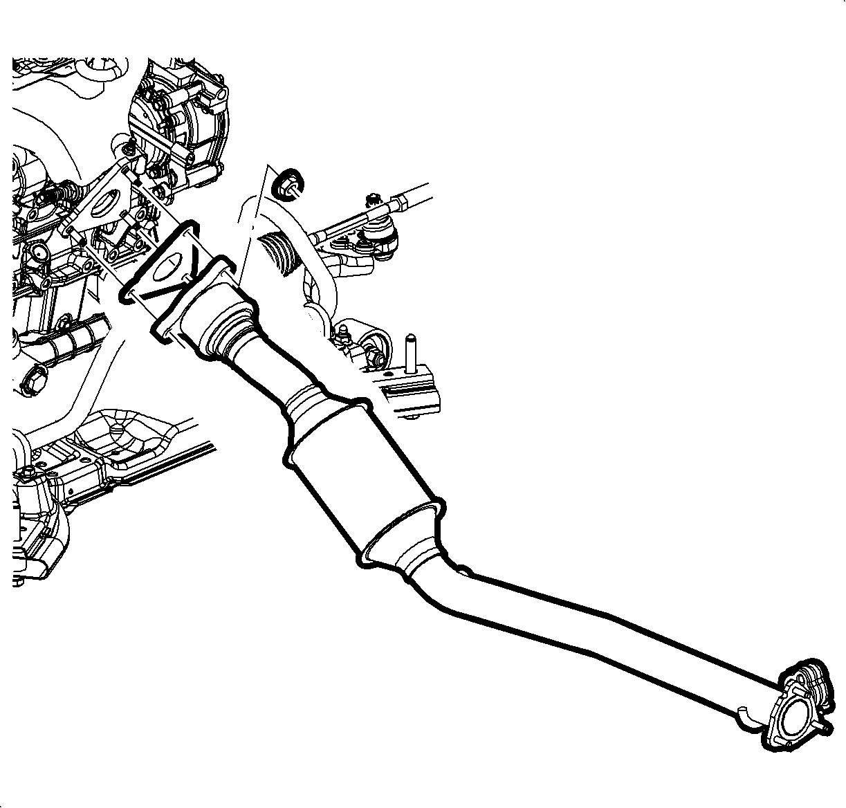
- Remove the exhaust manifold pipe to resonator pipe nuts behind the converter.
- Disconnect the rear O2 sensor wire from the heat shield.
- Separate the exhaust manifold pipe and resonator pipe. Discard the gaskets.
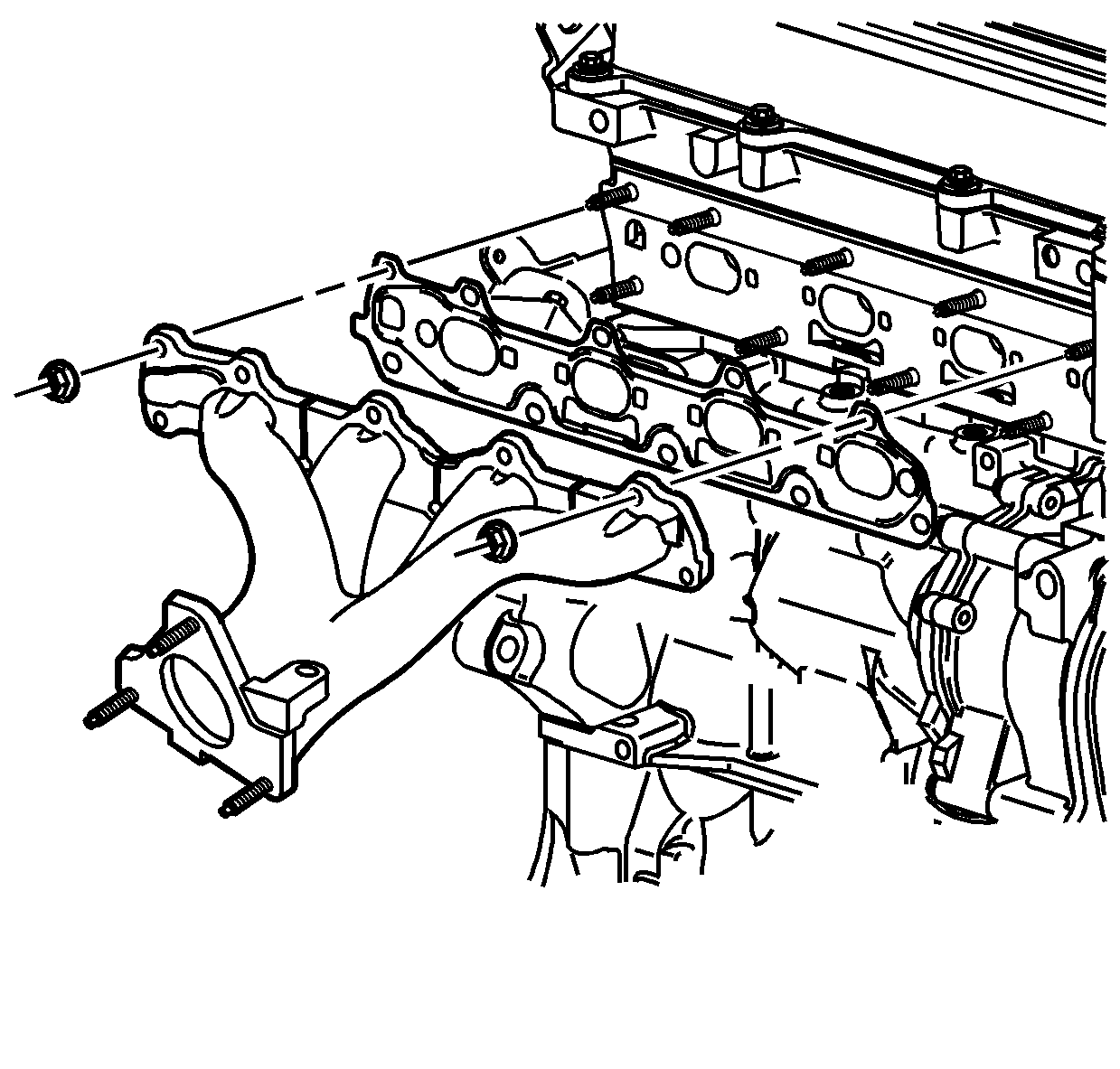
- Remove the exhaust manifold nuts.
- Remove the exhaust manifold assembly and discard the gasket.
- Remove the exhaust manifold gasket and discard.
Installation Procedure
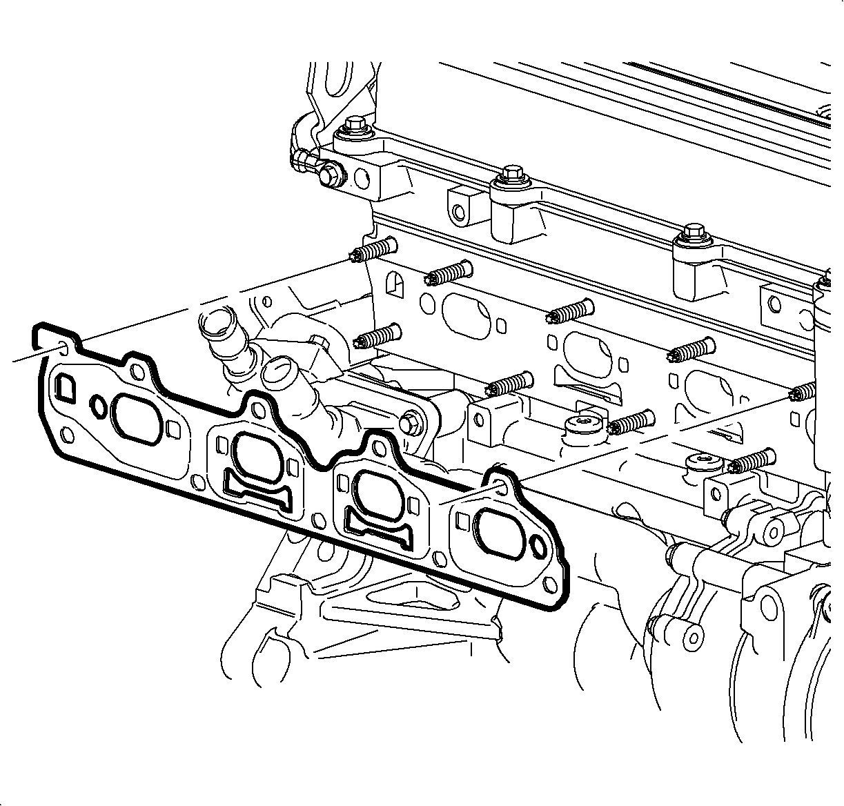
- Install a new manifold gasket on the cylinder head.
- Install the exhaust manifold.
- Install the exhaust manifold nuts.
- If necessary, transfer the O2 sensor from the old manifold.
- Install the O2 sensor into the exhaust manifold.
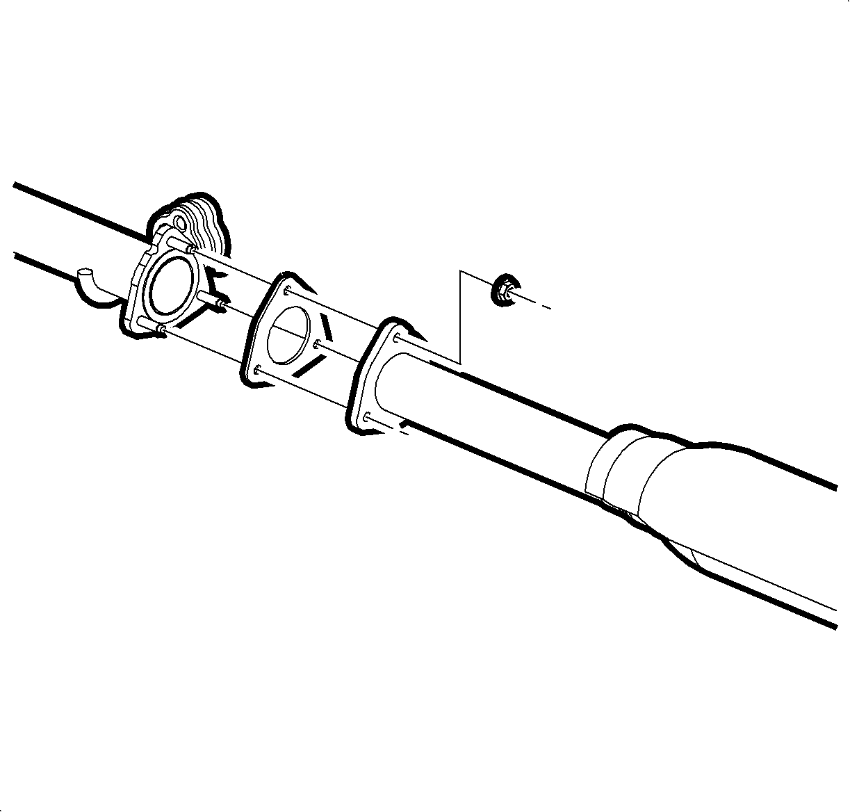
- Install the gasket and exhaust pipe to the intermediate pipe.
- Install the exhaust pipe-to-intermediate pipe nuts.
- Attach the rear O2 sensor wire to the heat shield.
- Install a new exhaust manifold gasket onto the exhaust manifold flange studs.
- Position the exhaust manifold pipe onto the exhaust manifold studs and install the exhaust manifold nuts.
- Lower the vehicle.
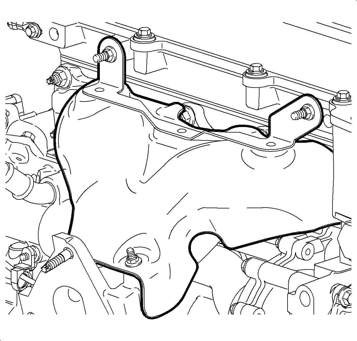
- Install the exhaust manifold heat shield.
- Install the exhaust manifold heat shield bolts.
- Install the outlet resonator/duct assembly into position.
- Connect the PVC fresh air vent hose assembly.
- Tighten the clamp at the throttle body assembly.
- Position the outlet resonator/duct assembly up with the support bracket and install the push-pin.
- Tighten the air cleaner assembly.
- Connect the intake air temperature (IAT) sensor connector.


Notice: Refer to Fastener Notice in the Preface section.
Tighten
Tighten the exhaust manifold-to-cylinder head nuts
L61 to 18 N·m (13 lb ft).
Important: Whenever the oxygen sensor is removed, coat the threads with nickel-based anti-seize compound such as Permatex® 77124, SA P/N 21485279 or equivalent.
Tighten
Tighten the O2 sensor to 45 N·m (33 lb ft).
Tighten
Tighten the exhaust pipe-to-intermediate pipe nuts
L61 to 30 N·m (22 lb ft).

Tighten
Tighten the exhaust manifold pipe-to-exhaust manifold
nuts L61 to 42 N·m (31 lb ft).
Tighten
Tighten the exhaust manifold heat shield bolts L61
to 23 N·m (17 lb ft).

