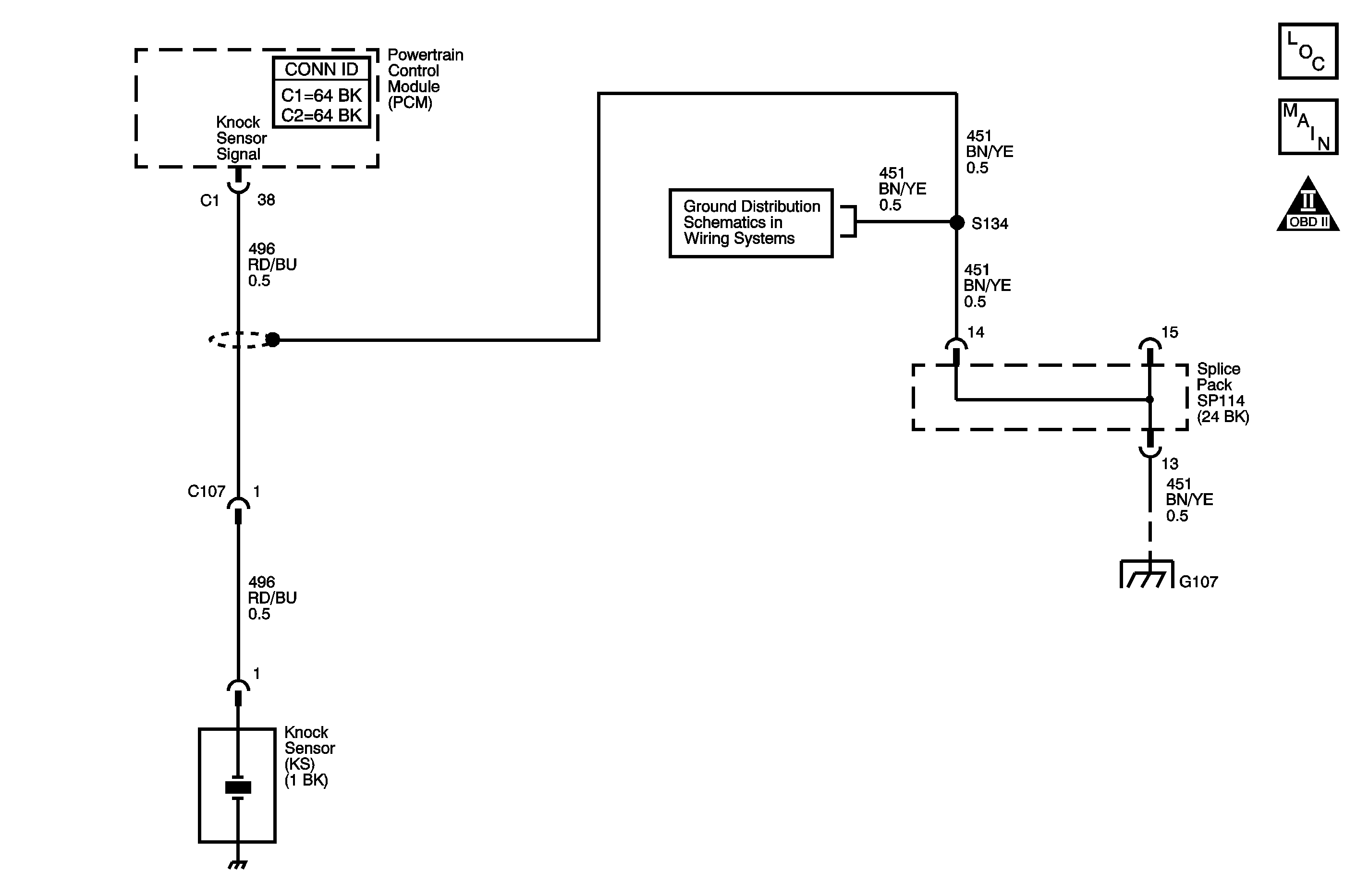
Circuit Description
The DTC P0325 Knock Sensor (KS) Circuit diagnostic monitors the activity on the knock sensor circuit. The KS is used to detect engine detonation. The KS is constructed of a piezoelectric element which generates an AC signal when vibrated. Normal engine operation will cause the KS to generate a signal of a certain known frequency. When engine knock is present, the KS frequency changes which signals the PCM to retard ignition timing. By retarding the ignition timing, the engine detonation detected should be reduced.
DTC Descriptors
This diagnostic procedure supports the following DTC.
DTC P0325 Knock Sensor (KS) Circuit
Conditions for Running the DTC
| • | The engine speed is at least 2,000 RPM. |
| • | The engine coolant temperature (ECT) is at least 60°C (140°F). |
| • | DTC P0325 runs continuously once the above conditions are met. |
Conditions for Setting the DTC
No KS signal is detected for more than 5 seconds.
Action Taken When the DTC Sets
| • | The PCM illuminates the MIL. |
| • | The PCM stores the conditions which were present when the DTC set as Freeze Frame data. |
Conditions for Clearing the MIL/DTC
| • | The PCM turns OFF the MIL on the third consecutive trip cycle during which the diagnostic has been run and the fault condition is no longer present. |
| • | The DTC clears after 40 consecutive warm-up cycles have occurred without a fault. |
| • | A DTC can be cleared by using the scan tool Clear DTC Information function. |
Diagnostic Aids
| • | A loose KS can cause a loss of the KS signal. Check the KS for the proper torque. |
| • | An intermittent malfunction may be caused by a fault in the KS sensor electrical circuit. Inspect the wiring harness and the components for an intermittent condition. Refer to Intermittent Conditions . |
The information included in the Freeze Frame data can be useful in determining the vehicle operating conditions present when the DTC first set.
Test Description
The numbers below refer to the step numbers in the diagnostic table.
-
The Diagnostic System Check-Engine Controls prompts the technician to complete some basic checks and store the Freeze Frame data on the scan tool if applicable. This creates an electronic copy of the data taken when the fault occurred. The information is then stored in the scan tool for later reference.
-
This step checks whether DTC P0325 is the result of a hard failure or an intermittent condition.
-
This step tests the KS signal circuit and the PCM. Shorting the signal circuit to 5 volts enables validation of the signal wire and the PCM recognition of a voltage input. The EGR valve is the most convenient 5-volt supply for performing this test.
-
After replacing the PCM a new minimum throttle position and idle speed must also be established.
Step | Action | Values | Yes | No |
|---|---|---|---|---|
Connector End View Reference: Powertrain Control Module Connector End Views or Engine Controls Connector End Views | ||||
Did you perform the Diagnostic System Check-Engine Controls? | -- | Go to Step 2 | ||
Did the Knock Control parameter switch from Inactive to Active at least once during AA acceleration event? | -- | Go to Step 3 | Go to Step 4 | |
3 |
Does DTC P0325 set? | -- | Go to Step 4 | Go to Diagnostic Aids |
Is the DC voltage within the specified range? | 3.8-4.0 V | Go to Step 5 | Go to Step 6 | |
5 | Replace the knock sensor. Refer to Knock Sensor Replacement . Is the action complete? | -- | Go to Step 8 | -- |
6 |
Ensure that the terminal connection at the sensor is good. Did you find and repair a wiring condition? | -- | Go to Step 8 | Go to Step 7 |
Did you complete the replacement? | -- | Go to Step 8 | -- | |
8 |
Does the DTC run and pass? | -- | Go to Step 9 | Go to Step 2 |
9 | With a scan tool, observe the stored information, Capture Info. Does the scan tool display any DTCs that you have not diagnosed? | -- | System OK | |
