Tools Required
| • | J 8614-01 Flange and Pulley Holding Tool |
| • | J 44872 Pinion Shaft Seal Installer |
| • | J 44873 Shoulder Bolts |
| • | J 44882 Pinion Press Support Bar |
Removal Procedure
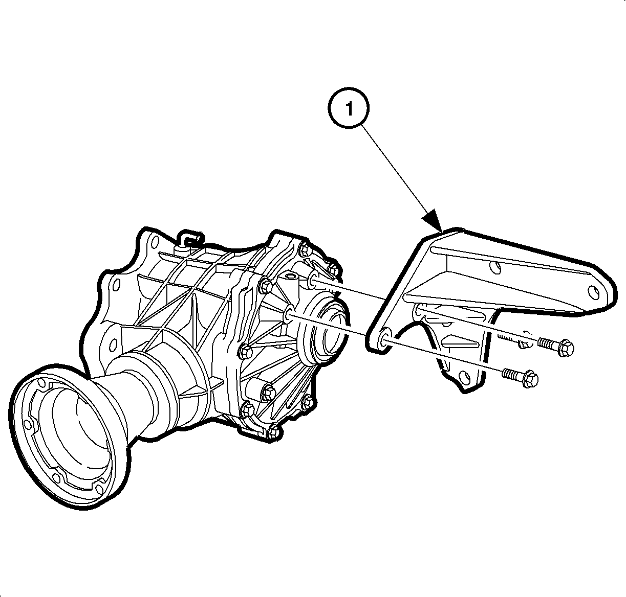
- Remove the 3 bolts from the bracket (1).
- Remove the bracket (1).
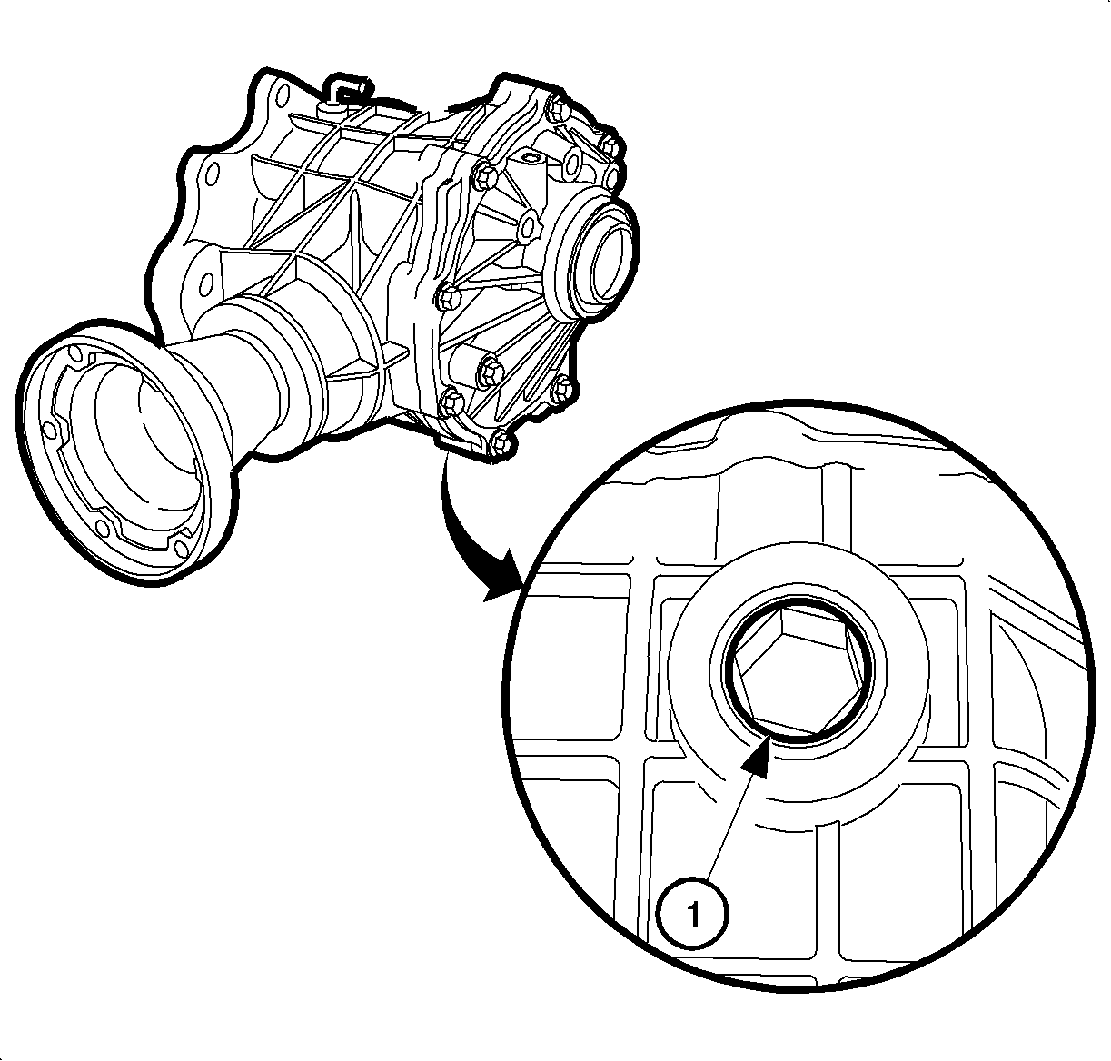
- Remove the drain plug (1).
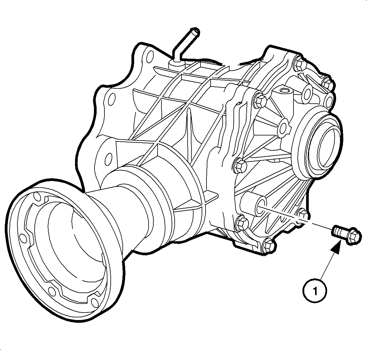
- Remove the fill plug (1) and drain the fluid.
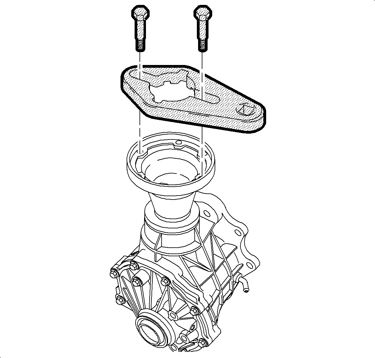
- Install the J 44873 and the 2 attaching bolts to the pinion flange.
- Using a breaker bar and a ratchet with a 27 mm socket, remove the pinion nut.
- Insert the J 8614-01 (1) through the slots in the J 44873 .
- Turn the blue collar until it locks into the grooves on the underside of the J 44873 .
- Tighten the forcing screw to remove the pinion flange.
- Remove the J 44873 (2), the 2 attaching bolts and the J 8614-01 (1) from the pinion flange.
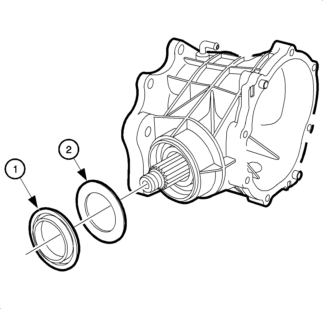
- Remove the oil seal (1) and slinger washer (2) from the housing.
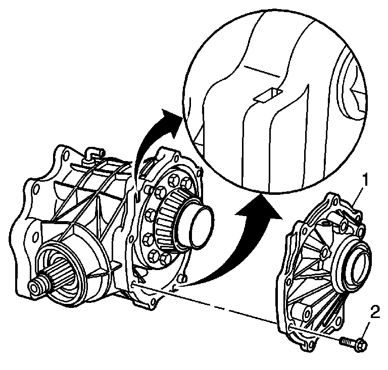
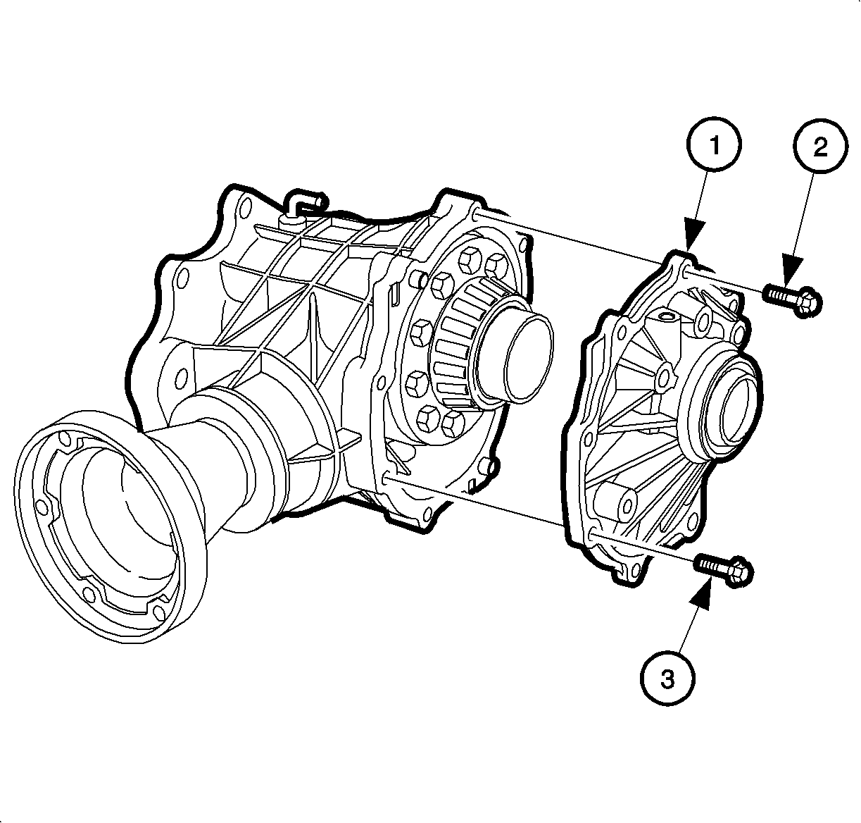
- Remove all bolts (2) from the side cover (1).
- Use the pry point relief slots to remove the cover.
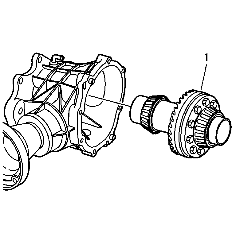
- Remove the carrier assembly (1) from the housing.
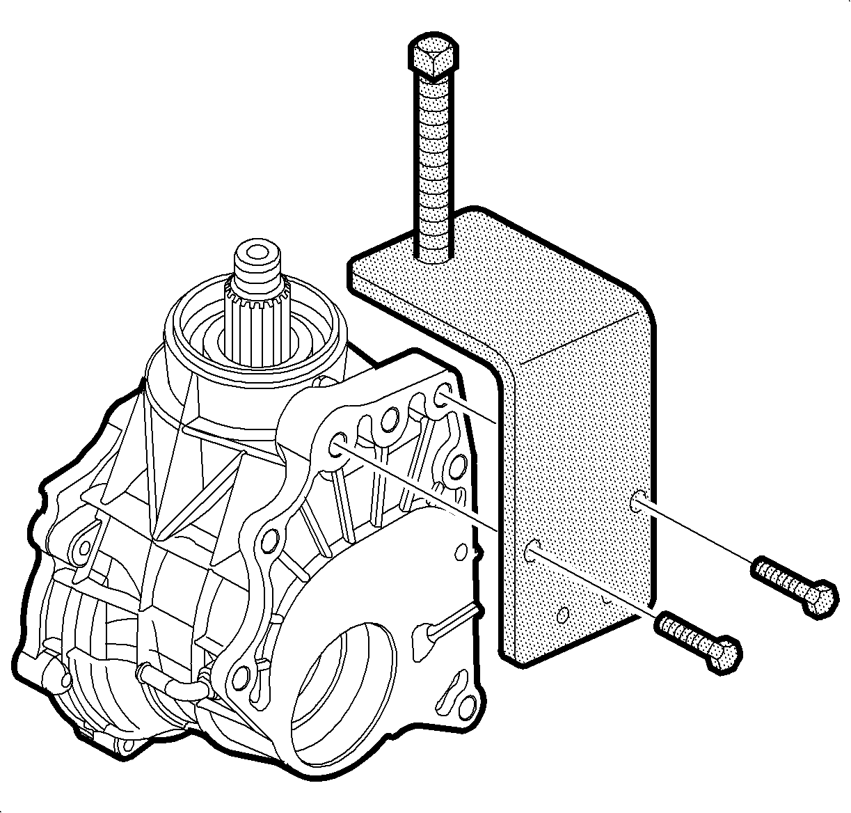
- Using the bolts supplied, attach the J 44882 to the carrier housing.
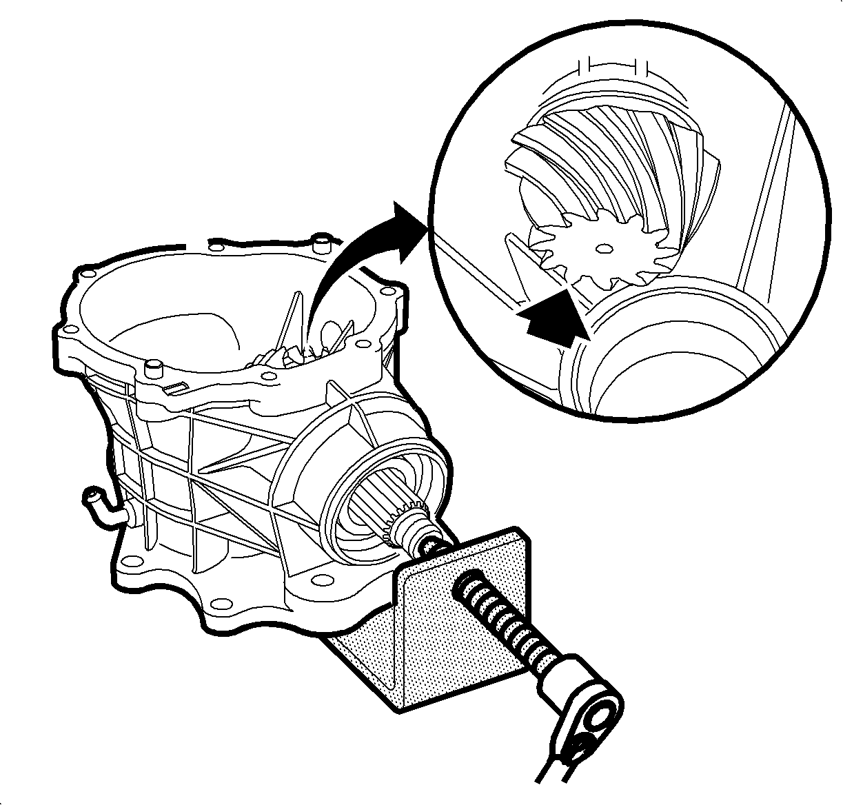
- Tighten the forcing screw in order to push out the pinion gear. The gear will spin when it is being pushed out. When the gear stops spinning, stop pushing. The gear teeth will contact the housing.
- Remove the J 44882 .
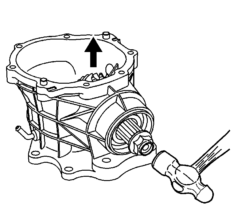
- Install the old pinion nut on the threads of the pinion shaft. Hold the shaft so the gear head faces up and drive out the pinion shaft so that it does not contact the housing.
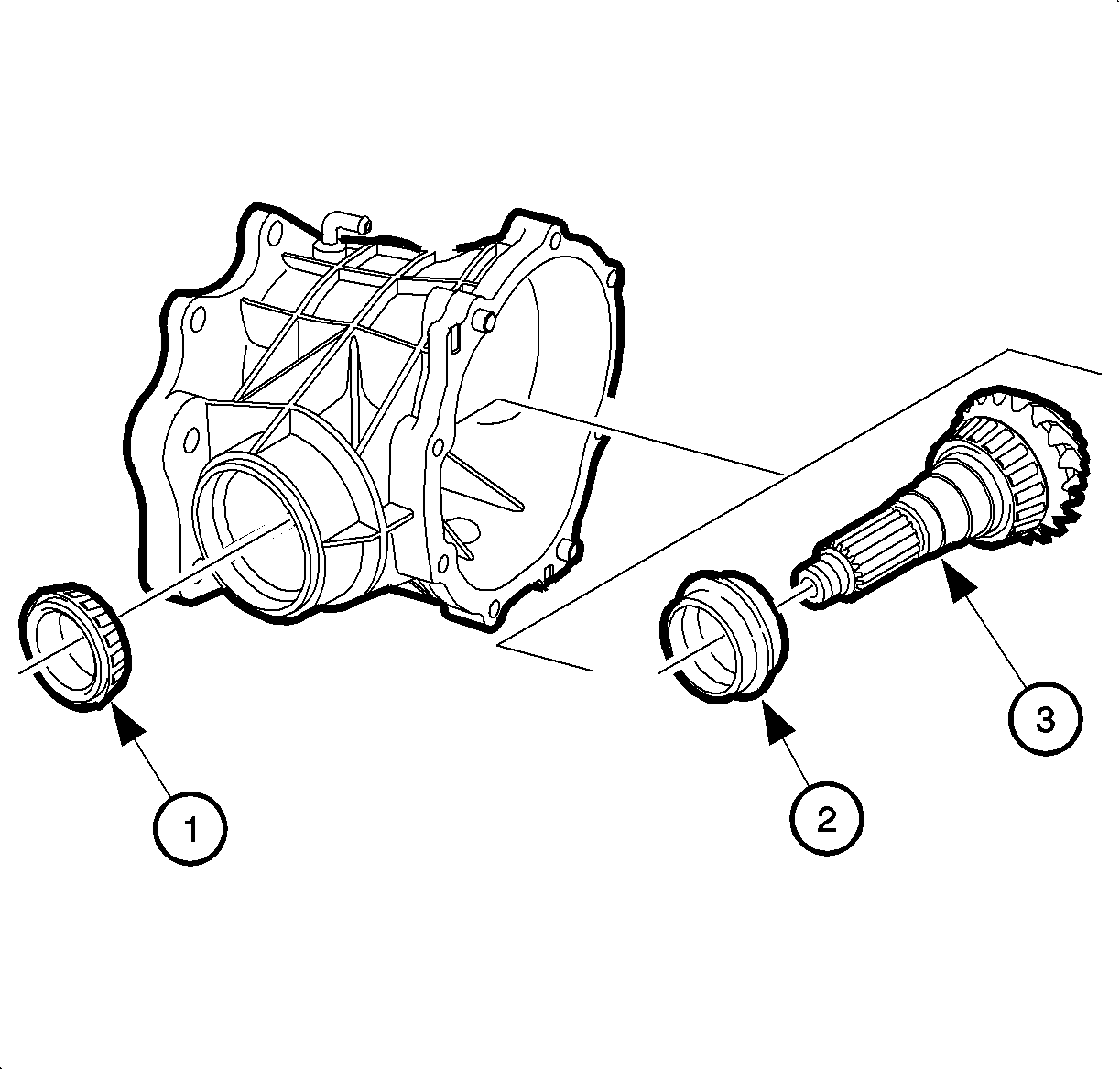
- Remove the bearing (1), collapsible spacer (2), and pinion shaft (3) from the housing.
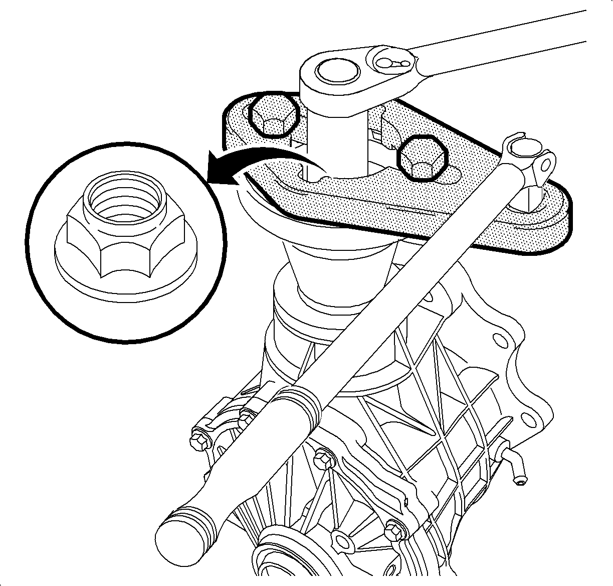
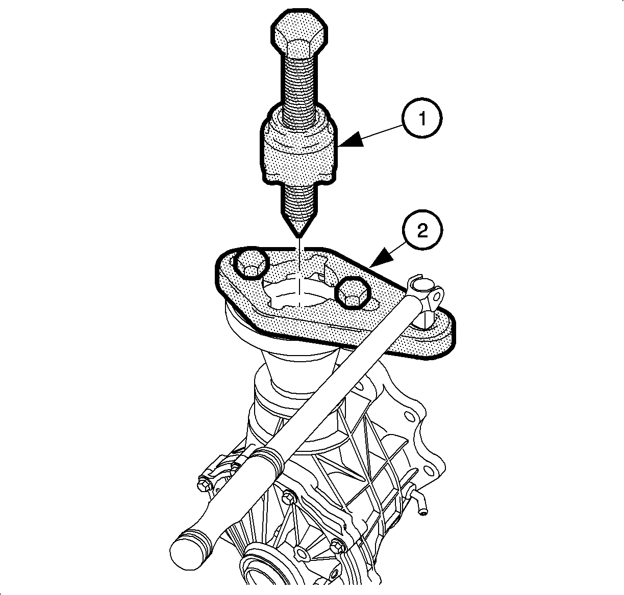
Important: Use high pressure grease on the screw threads.
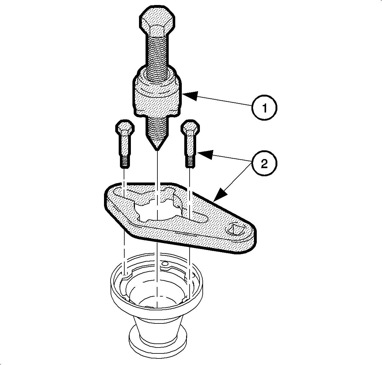
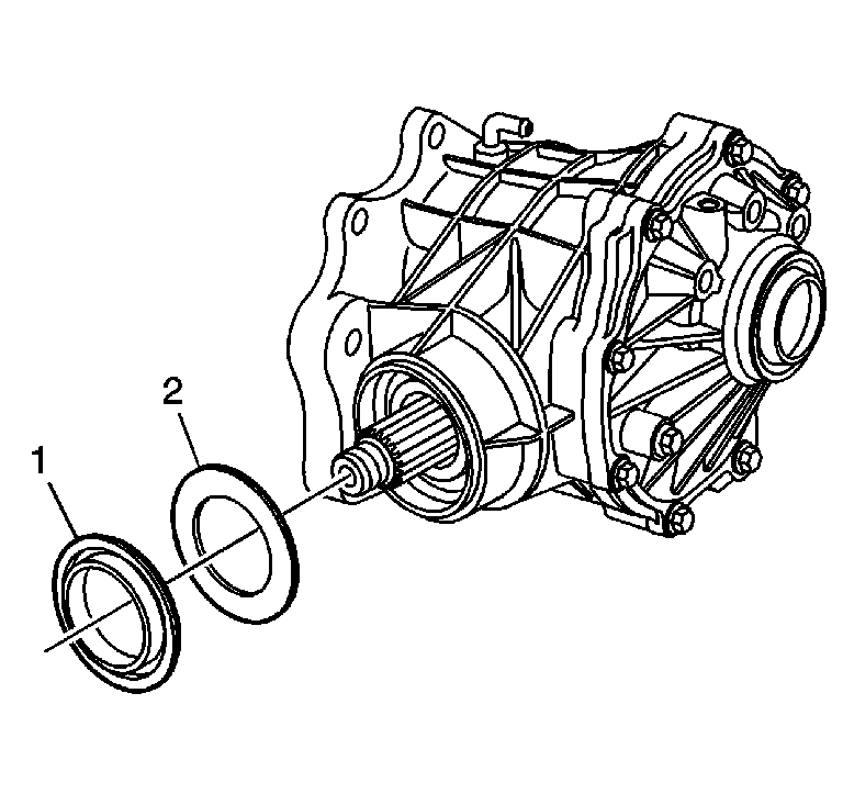
Notice: Do not use air tools. The use of an air tool will damage the J44882.
Important: Use high pressure grease on the threads of the forcing screw.
Installation Procedure
- Install the NEW collapsible spacer (2) onto the pinion shaft (3).
- Install the pinion shaft (3) into the housing.
- Install the bearing (1) onto the pinion shaft.
- Install the slinger washer (2) and the NEW pinion seal (1) to the housing.
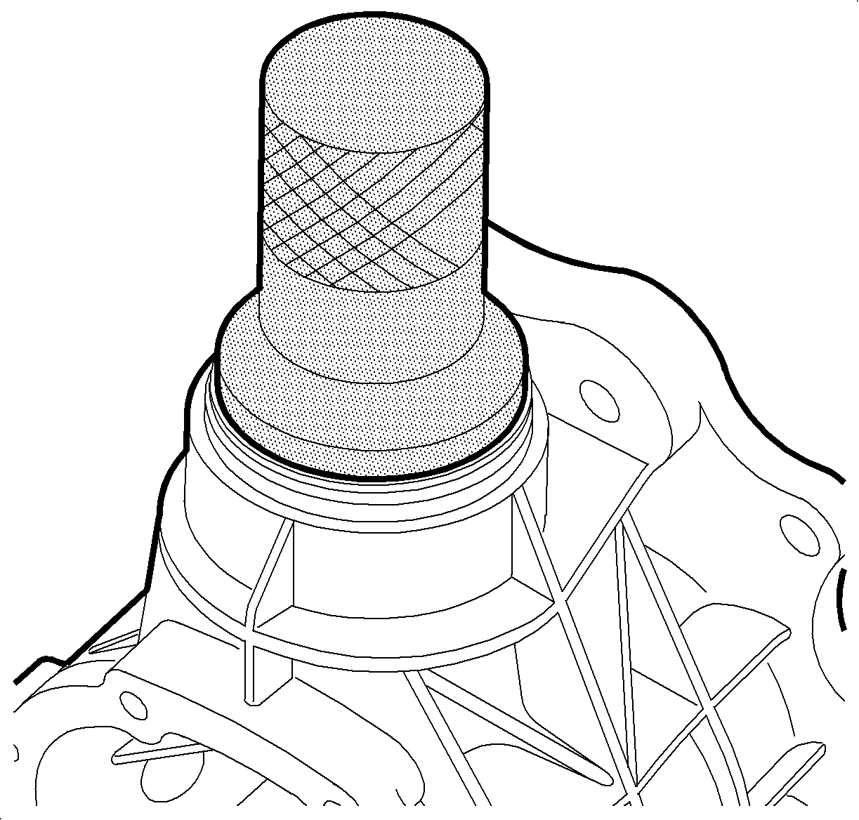
- Using the J 44872 , install the NEW pinion seal.
- Using a NEW pinion nut (1), install the pinion flange (2) to the pinion shaft.
- Install the J 44873 and the 2 bolts supplied in order to hold the pinion flange while tightening the nut.
- Tighten the pinion flange nut until it is snug.
- Tighten the nut slowly in order to crush the collapsible spacer.
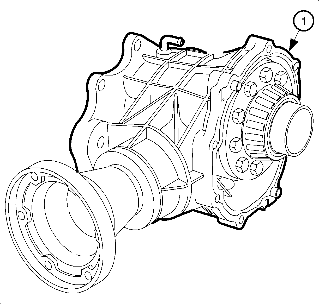
- Clean the carrier assembly housing sealing surface (1) with solvent and scrape it clean with a razor blade.
- Clean the cover sealing surface (1) with solvent and scrape it clean with a razor blade.
- Install the carrier assembly (1) to the housing.
- Apply 2-3 mm (0.08-0.12 in) of sealer Saturn P/N 1052943 or equivalent to the housing (1).
- Install the side cover (1) and bolts (2, 3) to the housing.
- Apply sealant Saturn P/N 21485278 to the drain plug threads.
- Install the drain plug.
- After the transfer case is installed in the vehicle, fill the transfer case with fluid to the bottom of the fill plug hole, or 540 ml (18.2 oz).
- Apply sealant Saturn P/N 21005994 to the fill plug threads.
- Install the fill plug.

Important: Clean the seal bores. Inspect for nicks caused by seal removal.
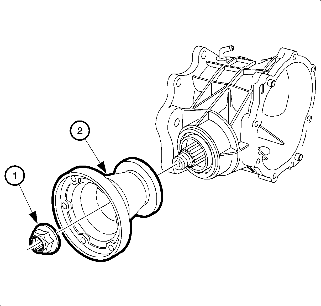
Important: Use a NEW pinion nut.
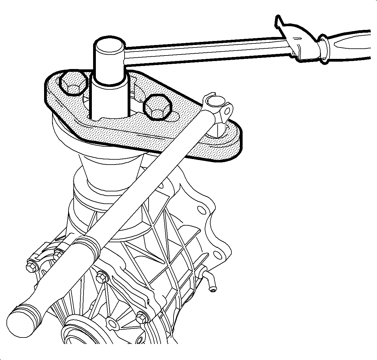
Notice: Refer to Fastener Notice in the Preface section.
Tighten
Tighten the pinion flange nut to achieve a rotating torque of 0.9-1.6 N·m (8-14 lb in).
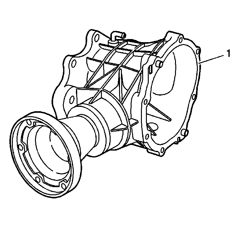
Important: Do not use motor-powered tools to clean surfaces.
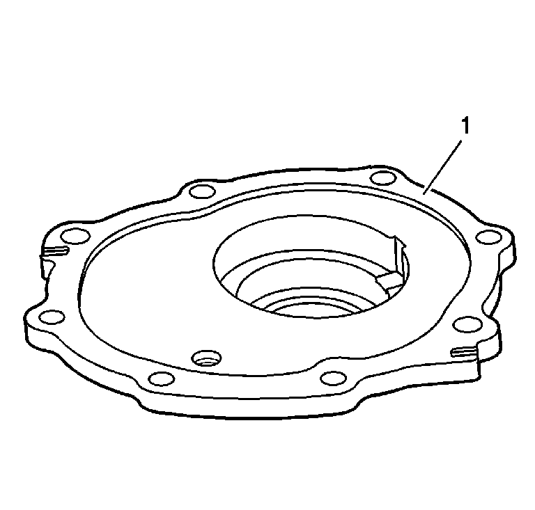

Important: Use gear lubricant fluid Saturn P/N 12378514 to grease the seal lips in order to protect the seal and to ease in assembly.
Notice: Refer to Excessive Amounts of Sealant Notice in the Preface section.
Important:
• Grease the seal lips in order to protect the seal and to ease in assembly. • Apply sealant Saturn P/N 12345382 to the bolt threads.
There is not a specific tightening sequence, but the bolts with dowel pins should be tightened first, and alternate the others from side to side.
Tighten
Tighten the side cover bolts to 37 N·m (27 lb ft).
Tighten
Tighten the drain plug to 24 N·m (18 lb ft).
Tighten
Tighten the fill plug to 15 N·m (11 lb ft).
