| Table 1: | DTC P0118 |
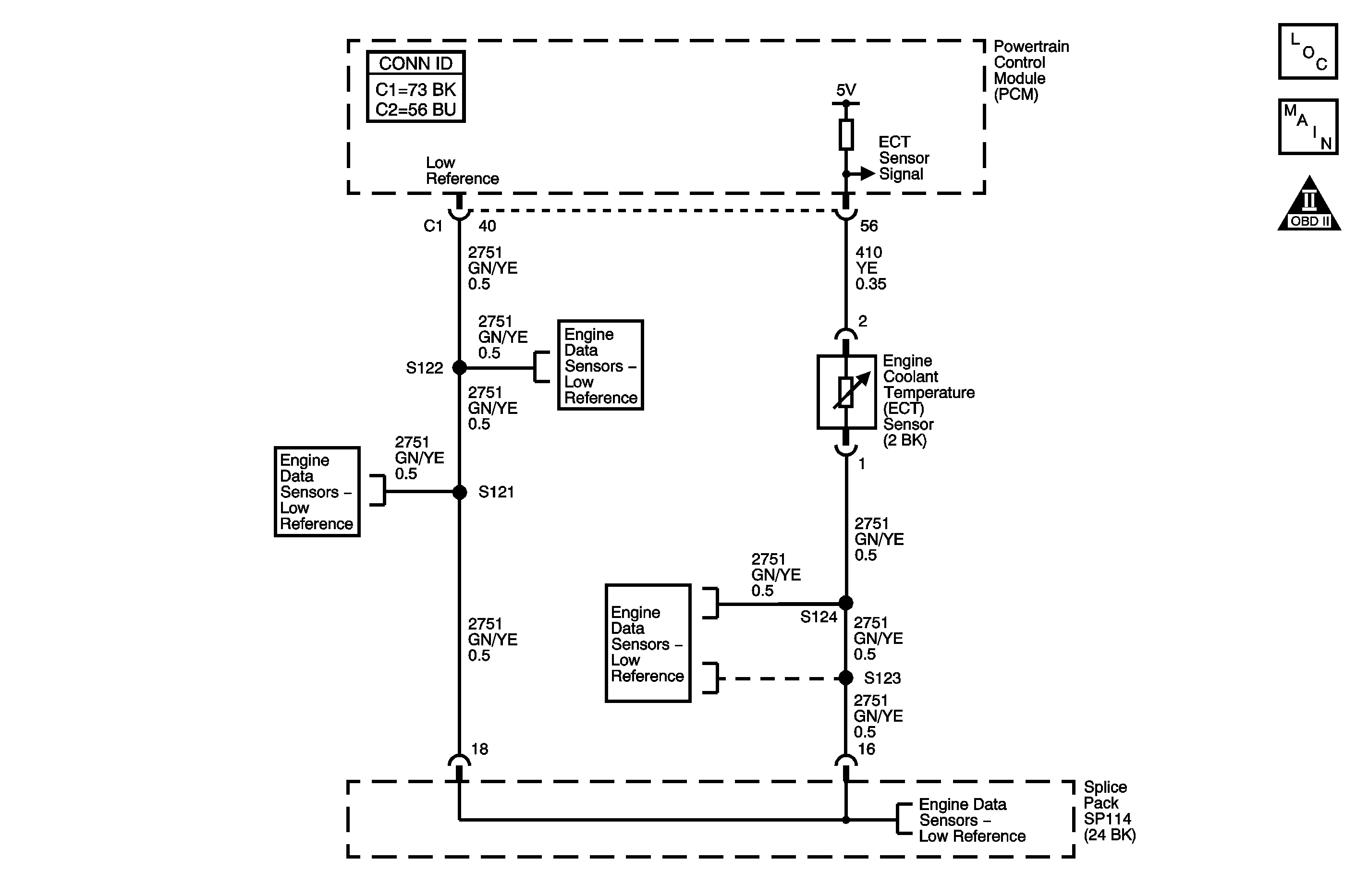
Circuit Description
The DTC P0118 Engine Coolant Temperature (ECT) Sensor Circuit High Voltage diagnostic monitors the signal circuit value. The ECT sensor is a variable resistor that measures the temperature of the engine coolant. The powertrain control module (PCM) supplies 5 volts to the ECT signal circuit and supplies a ground to the low reference circuit. If the PCM detects a high ECT signal voltage, which is a low temperature indication, this DTC sets.
The following table illustrates the difference between temperature, resistance, and voltage:
ECT | ECT Resistance | ECT Signal Voltage |
|---|---|---|
Cold | High | High |
Warm | Low | Low |
DTC Descriptor
This diagnostic procedure supports the following DTC.
DTC P0118 Engine Coolant Temperature (ECT) Sensor Circuit High Voltage
Conditions for Running the DTC
| • | The ignition is ON. |
| • | DTC P0117, is not set. |
| • | DTC P0118 runs continuously once the above conditions are met. |
Conditions for Setting the DTC
| • | The PCM detects that the ECT sensor signal voltage is 4.92 volts or more. |
| • | The above condition is present for at least 2 seconds. |
Action Taken When the DTC Sets
| • | The powertrain control module (PCM) illuminates the malfunction indicator lamp (MIL) when the diagnostic runs and fails. |
| • | The PCM records the operating conditions at the time the diagnostic fails. The PCM stores this information in the Freeze Frame/Failure Records. |
| • | The PCM enters the Fail Safe Function in which the coolant temperature will use default values and the fuel control system will operate in OPEN LOOP. |
Conditions for Clearing the MIL/DTC
| • | The PCM turns OFF the malfunction indicator lamp (MIL) after 3 consecutive ignition cycles that the diagnostic runs and does not fail. |
| • | A last test failed, or current DTC, clears when the diagnostic runs and does not fail. |
| • | A history DTC clears after 40 consecutive warm-up cycles, if no failures are reported by this or any other emission related diagnostic. |
| • | Use a scan tool in order to clear the MIL and the DTC. |
Diagnostic Aids
| • | If a short to a separate 5-volt source occurs this DTC may set, if this is found to be the condition a continuity test to all other PCM circuits will be necessary to diagnose the specific circuit. |
| • | Use the Temperature vs Resistance table in order to test the ECT sensor at various temperature levels in order to evaluate the possibility of a skewed sensor. A skewed sensor could result in a driveability condition. If the engine has sat overnight, the engine coolant temperature and the intake air temperature values should display within a few degrees. If the temperatures are not within 3°C (5°F), refer to Temperature Versus Resistance - Intake Air Temperature Sensor . |
| • | After starting the engine, the ECT should rise steadily to about 90°C (194°F) then stabilize when the thermostat opens. |
| • | For an intermittent condition, refer to Intermittent Conditions . |
Test Description
The numbers below refer to the step numbers on the diagnostic table.
-
Tests for the proper operation of the circuit in the low voltage range. If the fuse in the jumper opens when you perform this test, the signal circuit is shorted to voltage.
-
This step tests the signal circuit of the ECT sensor for a short to another 5.0 volt reference circuit.
-
After replacing the PCM a new minimum throttle position and idle speed must also be established.
Step - | Action | Values | Yes | No |
|---|---|---|---|---|
Connector End View Reference: Powertrain Control Module Connector End Views or Engine Controls Connector End Views | ||||
1 | Did you perform the Diagnostic System Check-Engine Controls? | -- | Go to Step 2 | |
2 |
Does the scan tool indicate that the ECT is at the specified value? | -40°C (-40°F) | Go to Step 4 | Go to Step 3 |
3 |
Does the DTC fail this ignition cycle? | -- | Go to Step 4 | Go to Diagnostic Aids |
Does the scan tool indicate that the ECT is more than the specified value? | 168°C (334°F) | Go to Step 9 | Go to Step 5 | |
5 |
Does the scan tool indicate that the ECT is more than the specified value? | 168°C (334°F) | Go to Step 8 | Go to Step 6 |
6 | Did the fuse in the jumper wire open? | -- | Go to Step 11 | Go to Step 7 |
7 | Test the signal circuit of the ECT sensor for an open circuit or for high resistance. Refer to Circuit Testing and Wiring Repairs in Wiring Systems. Did you find and correct the condition? | -- | Go to Step 16 | Go to Step 12 |
8 | Test the low reference circuit of the ECT sensor for a high resistance or an open. Refer to Circuit Testing and Wiring Repairs in Wiring Systems. Did you find and correct the condition? | -- | Go to Step 16 | Go to Step 12 |
Do any additional DTCs set? | -- | Go to Step 13 | Go to Step 10 | |
10 | Test for an intermittent and for a poor connection at the ECT sensor. Refer to Testing for Intermittent Conditions and Poor Connections and Connector Repairs in Wiring Systems. Did you find and correct the condition? | -- | Go to Step 16 | Go to Step 14 |
11 |
Important: A short to voltage in signal circuit of the ECT sensor will cause ECT sensor failure. Replace the ECT sensor after you repair the short to voltage. Test the signal circuit of the ECT sensor for short to voltage. Refer to Circuit Testing and Wiring Repairs in Wiring Systems. Did you find and correct the condition? | -- | Go to Step 16 | Go to Step 15 |
12 | Test for an intermittent and for a poor connection at the PCM. Refer to Testing for Intermittent Conditions and Poor Connections and Connector Repairs in Wiring Systems. Did you find and correct the condition? | -- | Go to Step 16 | Go to Step 15 |
13 | Repair the short between the signal circuit of the ECT sensor and the circuit for which the DTC set. Refer to Wiring Repairs in Wiring Systems. Did you complete the repair? | -- | Go to Step 16 | -- |
14 | Replace the ECT sensor. Refer to Engine Coolant Temperature Sensor Replacement . Did you complete the replacement? | -- | Go to Step 16 | -- |
Did you complete the replacement? | -- | Go to Step 16 | -- | |
16 |
Does the DTC run and pass? | -- | Go to Step 17 | Go to Step 2 |
17 | With a scan tool, select Capture Info in order to observe the stored information. Does the scan tool display any DTCs that you have not diagnosed? | -- | System OK | |
