|
| ||||||||||||||
|---|---|---|---|---|---|---|---|---|---|---|---|---|---|---|---|
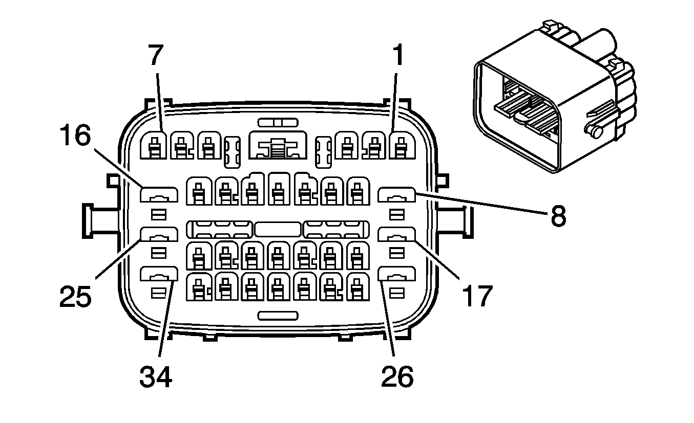
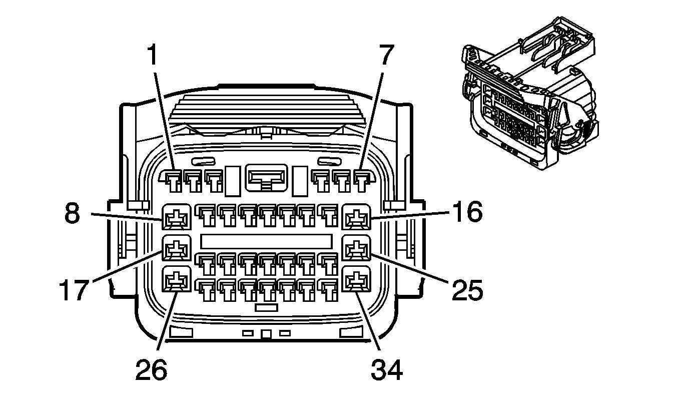
Connector Part Information |
| Connector Part Information |
| ||||||||||||
Pin | Wire Color | Circuit No. | Function | Pin | Wire Color | Circuit No. | Function | ||||||||
1 | D-BU | 1161 | APP Sensor 1 Signal | 1 | D-BU | 1161 | APP Sensor 1 Signal | ||||||||
2 | BN | 1271 | Low Reference | 2 | BN | 1271 | Low Reference | ||||||||
3 | WH/BK | 1164 | 5-Volt Reference B | 3 | WH/BK | 1164 | 5-Volt Reference B | ||||||||
4 | -- | -- | Not Used | 4 | -- | -- | Not Used | ||||||||
5 | PU | 1272 | 5-Volt Reference A | 5 | PU | 1272 | 5-Volt Reference A | ||||||||
6 | TN | 1274 | Low Reference | 6 | TN | 1274 | Low Reference | ||||||||
7 | L-BU | 1162 | APP Sensor 2 Signal | 7 | L-BU | 1162 | APP Sensor 2 Signal | ||||||||
8 | PK | 639 | Ignition 1 Voltage | 8 | PK | 639 | Ignition 1 Voltage | ||||||||
9 | TN/WH | 2500 | CAN High | 9 | TN/WH | 2500 | CAN High | ||||||||
10 | TN | 2501 | CAN Low | 10 | TN | 2501 | CAN Low | ||||||||
11-12 | -- | -- | Not Used | 11-12 | -- | -- | Not Used | ||||||||
13 | BK/WH | 771 | Transmission Range Switch Signal A | 13 | BK/WH | 771 | Transmission Range Switch Signal A | ||||||||
14 | YE | 772 | Transmission Range Switch Signal B | 14 | YE | 772 | Transmission Range Switch Signal B | ||||||||
15 | GY | 773 | Transmission Range Switch Signal C | 15 | GY | 773 | Transmission Range Switch Signal C | ||||||||
16 | BN | 418 | TCC PWM Solenoid Valve Control | 16 | BN | 418 | TCC PWM Solenoid Valve Control | ||||||||
17 | BN | 323 | HSD2 | 17 | BN | 323 | HSD2 | ||||||||
18 | OG | 1440 | Battery Positive Voltage | 18 | OG | 1440 | Battery Positive Voltage | ||||||||
19 | OG/BK | 586 | Low Reference | 19 | OG/BK | 586 | Low Reference | ||||||||
20 | YE/BK | 1227 | TFT Sensor Signal | 20 | YE/BK | 1227 | TFT Sensor Signal | ||||||||
21 | WH | 1804 | TCC Release Switch Signal | 21 | WH | 1804 | TCC Release Switch Signal | ||||||||
22 | RD | 1226 | Transmission Fluid Pressure Switch Signal C | 22 | RD | 1226 | Transmission Fluid Pressure Switch Signal C | ||||||||
23 | D-BU | 1225 | Transmission Fluid Pressure Switch Signal B | 23 | D-BU | 1225 | Transmission Fluid Pressure Switch Signal B | ||||||||
24 | WH | 776 | Transmission Range Switch Signal P | 24 | WH | 776 | Transmission Range Switch Signal P | ||||||||
25 | RD/BK | 1228 | PC Solenoid Valve High Control | 25 | RD/BK | 1228 | PC Solenoid Valve High Control | ||||||||
26 | YE | 400 | VSS High Signal | 26 | YE | 400 | VSS High Signal | ||||||||
27 | PU | 401 | VSS Low Signal | 27 | PU | 401 | VSS Low Signal | ||||||||
28 | D-GN | 890 | Fuel Tank Pressure Sensor Signal | 28 | D-GN | 890 | Fuel Tank Pressure Sensor Signal | ||||||||
29 | L-BU/WH | 1229 | PC Solenoid Valve Low Control | 29 | L-BU/WH | 1229 | PC Solenoid Valve Low Control | ||||||||
30 | L-GN | 1222 | 1-2 Shift Solenoid Valve Control | 30 | L-GN | 1222 | 1-2 Shift Solenoid Valve Control | ||||||||
31 | YE/BK | 1223 | 2-3 Shift Solenoid Valve Control | 31 | YE/BK | 1223 | 2-3 Shift Solenoid Valve Control | ||||||||
32 | GY | 2709 | 5-Volt Reference | 32 | GY | 2709 | 5-Volt Reference | ||||||||
33 | D-BU/WH | 1231 | AT ISS Low Signal | 33 | D-BU/WH | 1231 | AT ISS Low Signal | ||||||||
34 | RD/BK | 1230 | AT ISS High Signal | 34 | RD/BK | 1230 | AT ISS High Signal | ||||||||
|
| ||||||||||||||
|---|---|---|---|---|---|---|---|---|---|---|---|---|---|---|---|
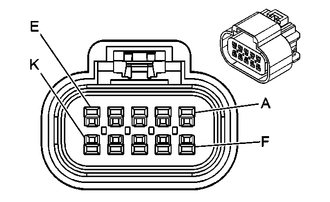
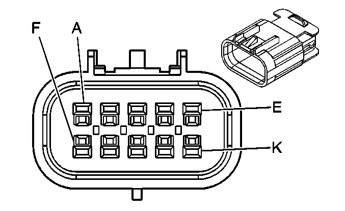
Connector Part Information |
| Connector Part Information |
| ||||||||||||
Pin | Wire Color | Circuit No. | Function | Pin | Wire Color | Circuit No. | Function | ||||||||
A | BN | 1271 | Low Reference | A | BN | 1271 | Low Reference | ||||||||
B | WH/BK | 1164 | 5-Volt Reference | B | WH/BK | 1164 | 5-Volt Reference | ||||||||
C | L-BU | 1162 | APP Sensor 2 Signal | C | L-BU | 1162 | APP Sensor 2 Signal | ||||||||
D | TN | 1274 | 5-Volt Reference | D | TN | 1274 | 5-Volt Reference | ||||||||
E | PU | 1272 | Low Reference | E | PU | 1272 | Low Reference | ||||||||
F | D-BU | 1161 | APP Sensor 1 Signal | F | D-BU | 1161 | APP Sensor 1 Signal | ||||||||
G | TN | 2501 | CAN Low | G | TN | 2501 | CAN Low | ||||||||
H | TN/WH | 2500 | CAN High | H | TN/WH | 2500 | CAN High | ||||||||
J | D-GN | 890 | Fuel Tank Pressure Sensor Signal | J | D-GN | 890 | Fuel Tank Pressure Sensor Signal | ||||||||
K | GY | 2709 | 5-Volt Reference | K | GY | 2709 | 5-Volt Reference | ||||||||

|

| ||||||||||||||
|---|---|---|---|---|---|---|---|---|---|---|---|---|---|---|---|
Connector Part Information |
| Connector Part Information |
| ||||||||||||
Pin | Wire Color | Circuit No. | Function | Pin | Wire Color | Circuit No. | Function | ||||||||
A | RD | 6743 | A/T Drive Signal | A | RD | 6743 | A/T Drive Signal | ||||||||
B | YE/GN | 6744 | A/T Intermediate Signal | B | YE/GN | 6744 | A/T Intermediate Signal | ||||||||
C | BU | 6742 | A/T Low Signal | C | BU | 6742 | A/T Low Signal | ||||||||
D | GN/WH | 1932 | A/T Park Signal | D | GN/WH | 1932 | A/T Park Signal | ||||||||
E | YE | 1479 | A/T Neutral Signal | E | RD/BK | 1479 | A/T Neutral Signal | ||||||||
F | L-BU | 2182 | A/T Reverse Signal | F | D-BU/WH | 2182 | A/T Reverse Signal | ||||||||
G | D-BU/YE | 6745 | A/T Forward Signal | G | D-BU/YE | 6745 | A/T Forward Signal | ||||||||
H | D-GN/WH | 459 | A/C Compressor Clutch Relay Control | H | D-GN/WH | 459 | A/C Compressor Clutch Relay Control | ||||||||
J-K | -- | -- | Not Used | J-K | -- | -- | Not Used | ||||||||
|
| ||||||||||||||
|---|---|---|---|---|---|---|---|---|---|---|---|---|---|---|---|
Connector Part Information |
| Connector Part Information |
| ||||||||||||
Pin | Wire Color | Circuit No. | Function | Pin | Wire Color | Circuit No. | Function | ||||||||
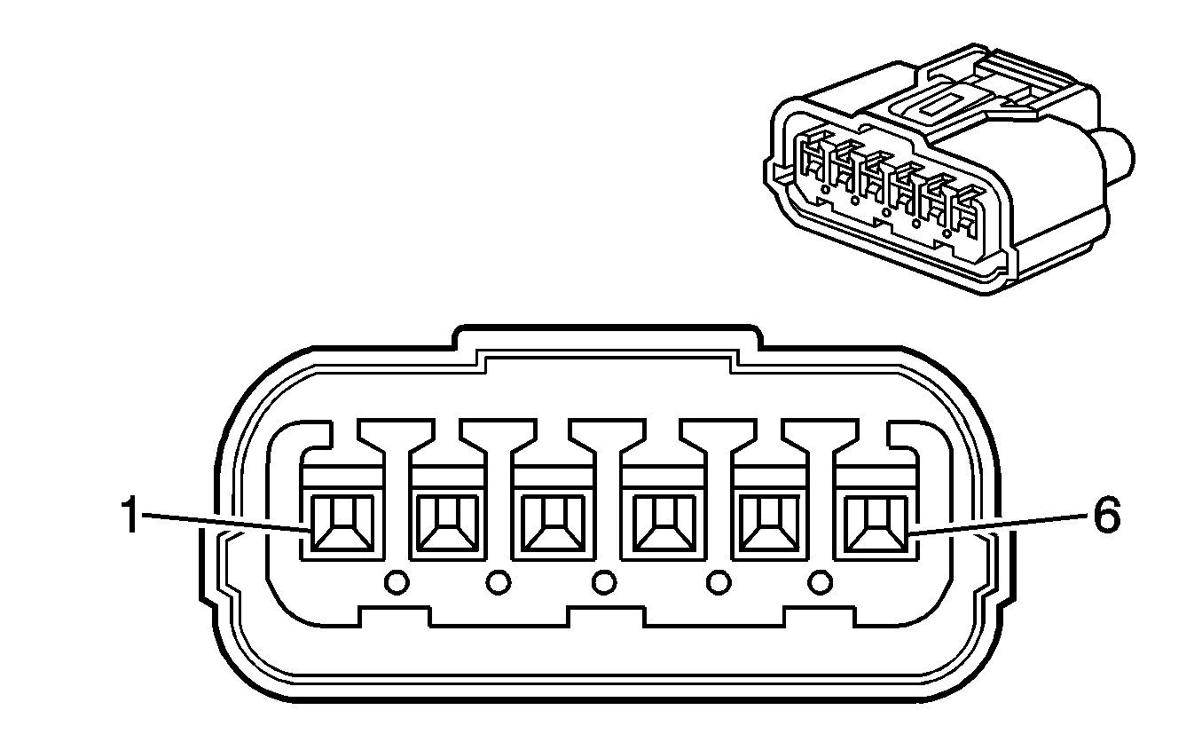
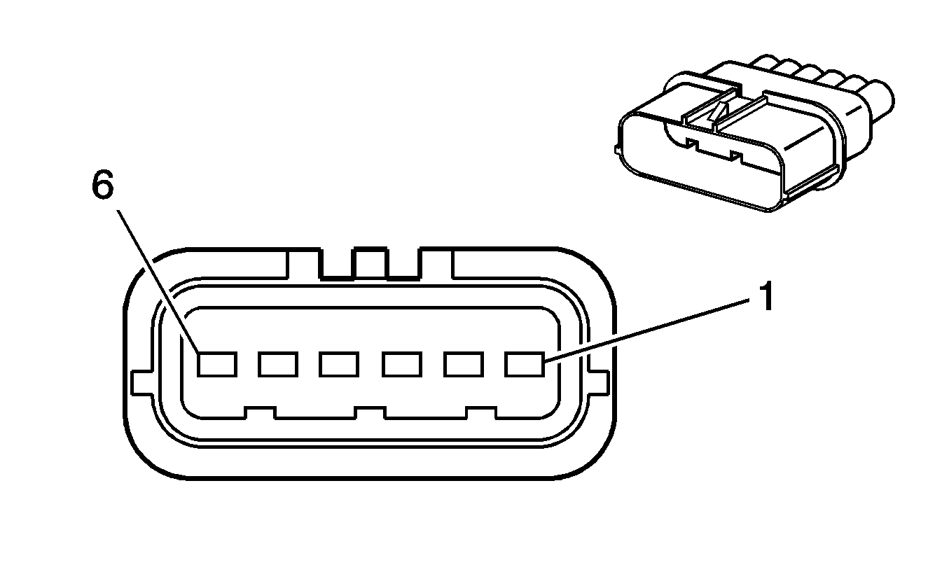
1 | WH | 5290 | Ignition 1 Voltage | 1 | YE/BK | 5290 | Ignition 1 Voltage | ||||||||
2 | BU | 573 | CKP Sensor A Signal | 2 | BU | 573 | CKP Sensor A Signal | ||||||||
3 | BN/YE | 451 | Ground | 3 | BN/YE | 451 | Ground | ||||||||
4 | WH | 5290 | Ignition 1 Voltage | 4 | YE/BK | 5290 | Ignition 1 Voltage | ||||||||
5 | BU/RD | 1800 | CKP Sensor B Signal | 5 | BU/RD | 1800 | CKP Sensor B Signal | ||||||||
6 | BN/YE | 451 | Ground | 6 | BN/YE | 451 | Ground | ||||||||
|
| ||||||||||||||
|---|---|---|---|---|---|---|---|---|---|---|---|---|---|---|---|
Connector Part Information |
| Connector Part Information |
| ||||||||||||
Pin | Wire Color | Circuit No. | Function | Pin | Wire Color | Circuit No. | Function | ||||||||
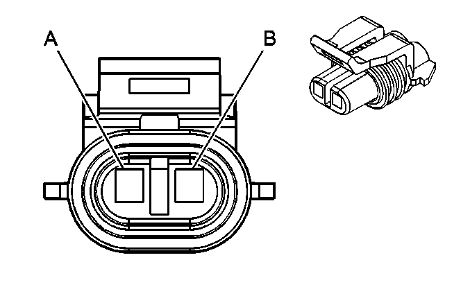
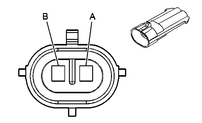
A | L-BU | 830 | Left Front Wheel Speed Sensor Signal | A | L-BU | 830 | Left Front Wheel Speed Sensor Signal | ||||||||
B | YE | 873 | Left Front Wheel Speed Sensor Low Reference | B | YE | 873 | Left Front Wheel Speed Sensor Low Reference | ||||||||

|

| ||||||||||||||
|---|---|---|---|---|---|---|---|---|---|---|---|---|---|---|---|
Connector Part Information |
| Connector Part Information |
| ||||||||||||
Pin | Wire Color | Circuit No. | Function | Pin | Wire Color | Circuit No. | Function | ||||||||
A | TN | 833 | Right Front Wheel Speed Sensor Low Reference | A | TN | 833 | Right Front Wheel Speed Sensor Low Reference | ||||||||
B | D-GN | 872 | Right Front Wheel Speed Sensor Signal | B | D-GN | 872 | Right Front Wheel Speed Sensor Signal | ||||||||
|
| ||||||||||||||
|---|---|---|---|---|---|---|---|---|---|---|---|---|---|---|---|
Connector Part Information |
| Connector Part Information |
| ||||||||||||
Pin | Wire Color | Circuit No. | Function | Pin | Wire Color | Circuit No. | Function | ||||||||
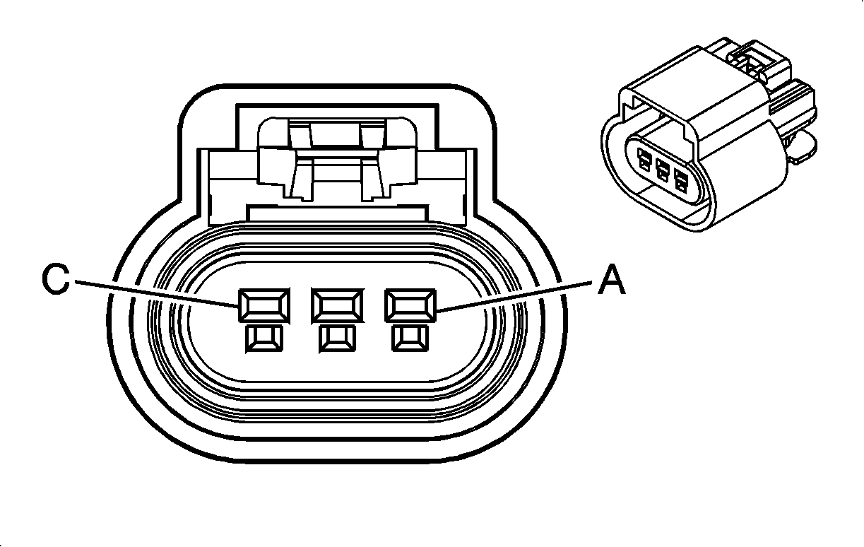
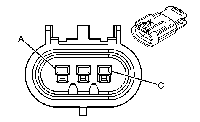
A | L-GN/BK | 735 | Ambient Air Temperature Sensor Signal | A | L-GN/BK | 735 | Ambient Air Temperature Sensor Signal | ||||||||
B | GY | 720 | Low Reference | B | GY | 720 | Low Reference | ||||||||
C | D-BU | 473 | High Speed Cooling Fan (2) Relay Control (L66) | C | D-BU | 473 | High Speed Cooling Fan (2) Relay Control (L66) | ||||||||
|
| ||||||||||||||
|---|---|---|---|---|---|---|---|---|---|---|---|---|---|---|---|
Connector Part Information |
| Connector Part Information |
| ||||||||||||
Pin | Wire Color | Circuit No. | Function | Pin | Wire Color | Circuit No. | Function | ||||||||
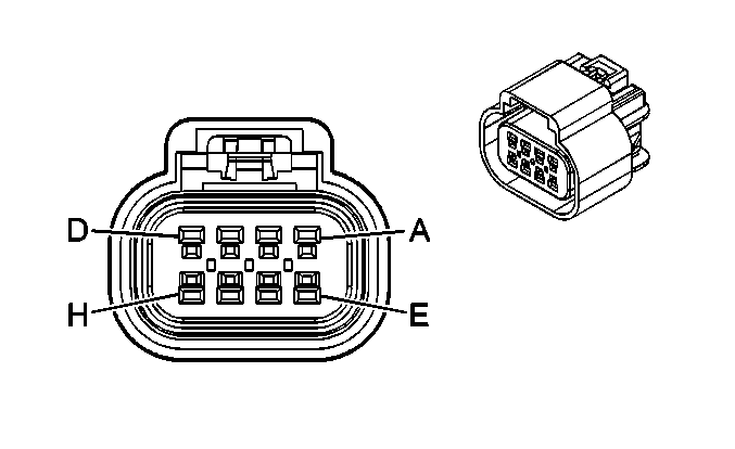
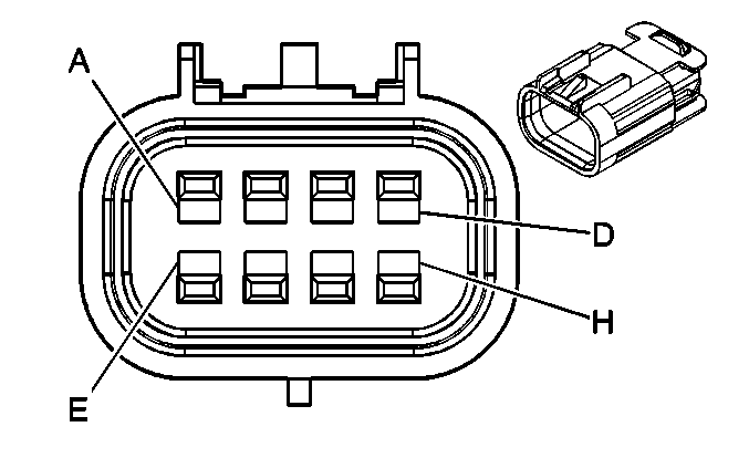
A | BK | 1744 | Fuel Injector 1 Control | A | BK | 1744 | Fuel Injector 1 Control | ||||||||
B | L-GN/BK | 1745 | Fuel Injector 2 Control | B | L-GN/BK | 1745 | Fuel Injector 2 Control | ||||||||
C | PK/BK | 1746 | Fuel Injector 3 Control | C | PK/BK | 1746 | Fuel Injector 3 Control | ||||||||
D | L-BU/BK | 844 | Fuel Injector 4 Control | D | L-BU/BK | 844 | Fuel Injector 4 Control | ||||||||
E | PK | 39 | Ignition 1 Voltage | E | PK | 39 | Ignition 1 Voltage | ||||||||
F | OG/BK | 469 | Low Reference | F | OG/BK | 469 | Low Reference | ||||||||
G | L-GN | 432 | MAP Sensor Signal | G | L-GN | 432 | MAP Sensor Signal | ||||||||
H | GY | 2704 | 5-Volt Reference B | H | GY | 2704 | 5-Volt Reference B | ||||||||
|
| ||||||||||||||
|---|---|---|---|---|---|---|---|---|---|---|---|---|---|---|---|
Connector Part Information |
| Connector Part Information |
| ||||||||||||
Pin | Wire Color | Circuit No. | Function | Pin | Wire Color | Circuit No. | Function | ||||||||
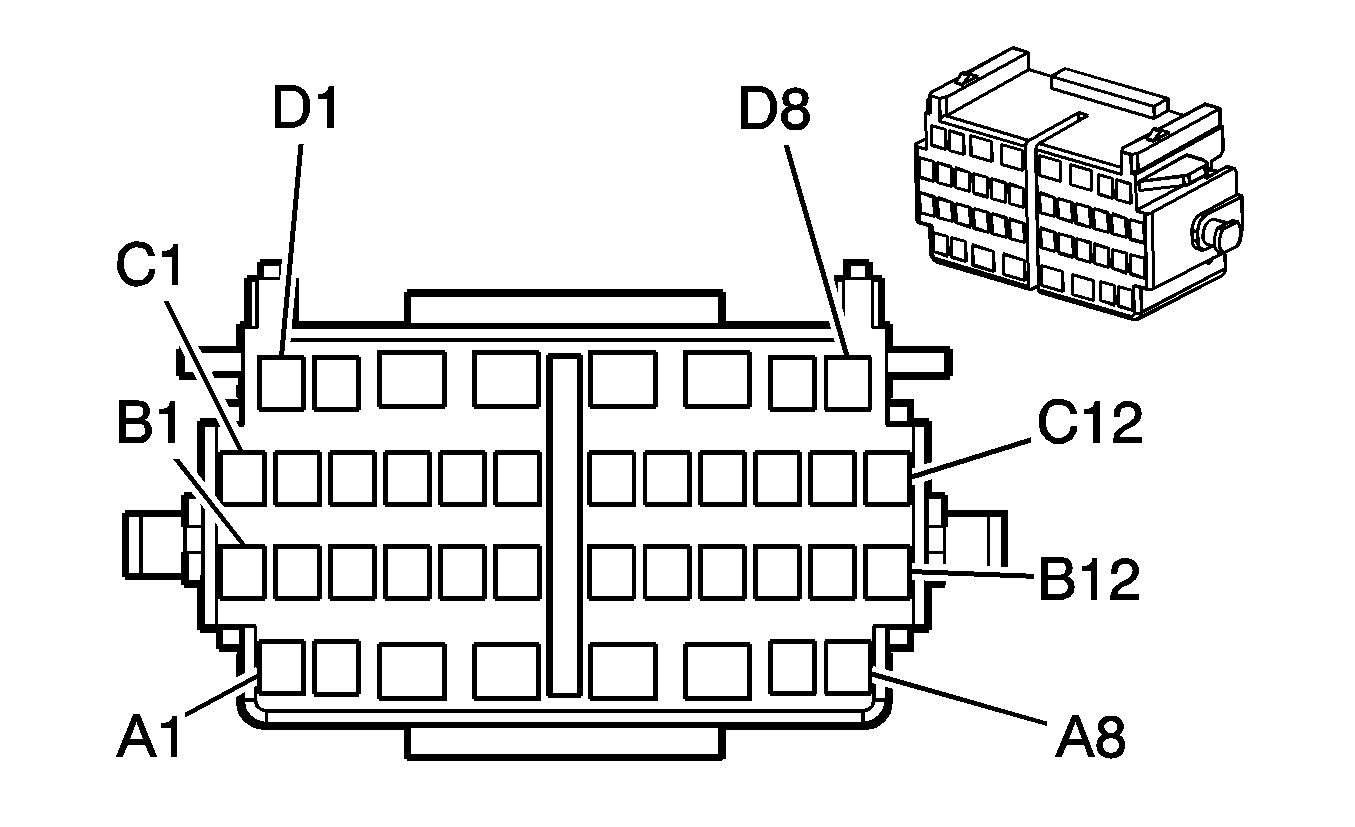
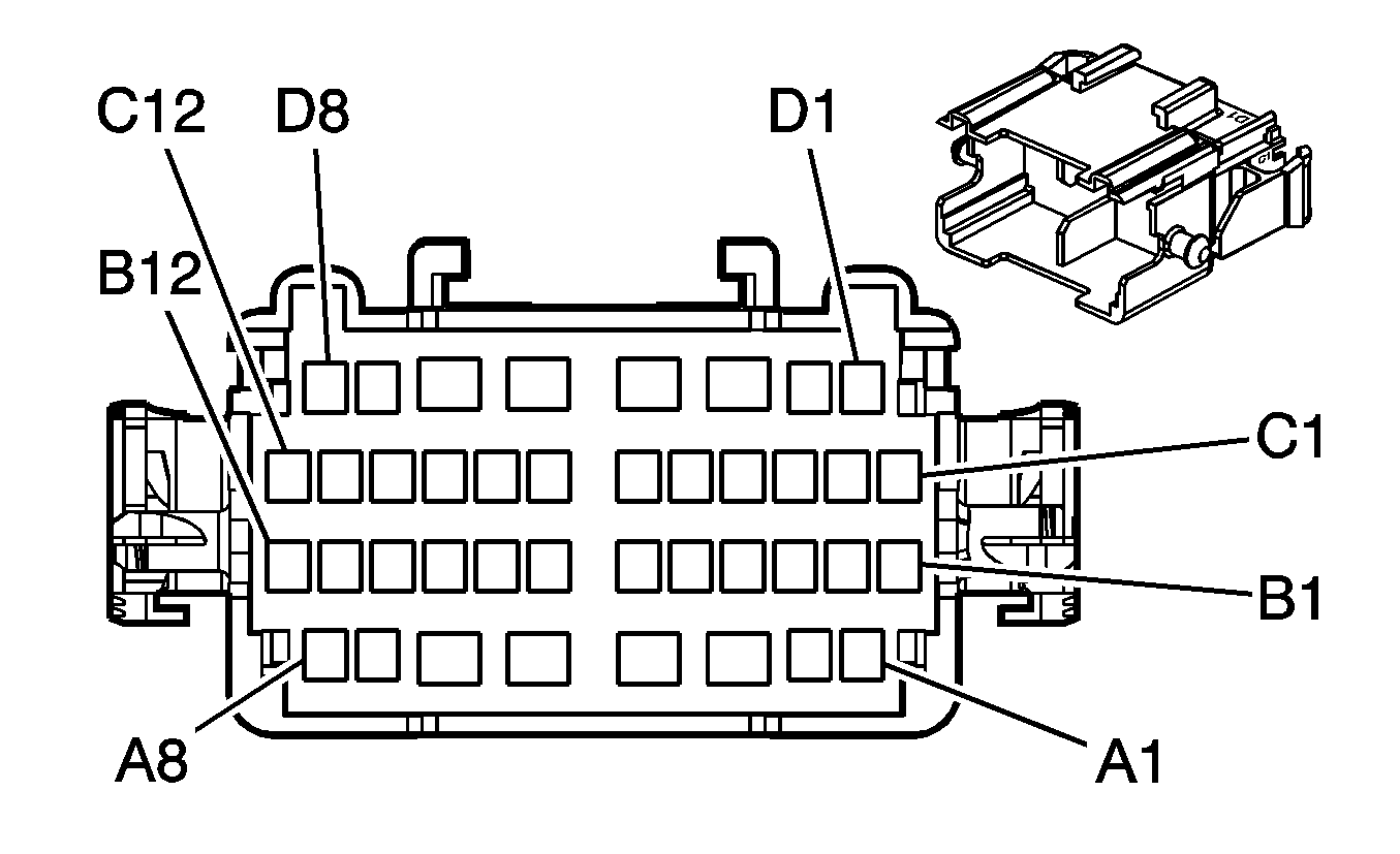
A1 | L-BU | 115 | Right Rear Speaker Output (-) | A1 | L-BU | 115 | Right Rear Speaker Output (-) | ||||||||
A2 | D-BU | 46 | Right Rear Speaker Output (+) | A2 | D-BU | 46 | Right Rear Speaker Output (+) | ||||||||
A3 | YE | 343 | Accessory Voltage | A3 | YE | 343 | Accessory Voltage | ||||||||
A4 | YE | 5 | Crank Voltage (A/T) | A4 | YE | 5 | Crank Voltage (A/T) | ||||||||
PU | 6 | Starter Solenoid Crank Voltage (M/T) | YE | 6 | Starter Solenoid Crank Voltage (M/T) | ||||||||||
A5 | OG | 40 | Battery Positive Voltage | A5 | OG | 40 | Battery Positive Voltage | ||||||||
A6 | D-GN | 95 | Windshield Wiper Motor Low Speed | A6 | D-GN | 95 | Windshield Wiper Motor Low Speed | ||||||||
A7 | -- | -- | Not Used | A7 | -- | -- | Not Used | ||||||||
A8 | PU | 719 | Low Reference | A8 | PU | 719 | Low Reference | ||||||||
B1 | GY | 118 | Left Front Speaker Output (-) | B1 | GY | 118 | Left Front Speaker Output (-) | ||||||||
B2 | TN | 201 | Left Front Speaker Output (+) | B2 | TN | 201 | Left Front Speaker Output (+) | ||||||||
B3 | YE | 116 | Left Rear Speaker Output (-) | B3 | YE | 116 | Left Rear Speaker Output (-) | ||||||||
B4 | OG | 540 | Battery Positive Voltage | B4 | OG | 540 | Battery Positive Voltage | ||||||||
B5 | OG | 340 | Battery Positive Voltage | B5 | OG | 340 | Battery Positive Voltage | ||||||||
B6 | GY/BK | 87 | Cruise Control Resume/Accel Switch Signal | B6 | GY/BK | 87 | Cruise Control Resume/Accel Switch Signal | ||||||||
B7 | GY | 731 | Evaporator Temperature Sensor Signal | B7 | GY | 731 | Evaporator Temperature Sensor Signal | ||||||||
B8 | GY | 397 | Cruise Control On Switch Signal | B8 | GY | 397 | Cruise Control On Switch Signal | ||||||||
B9 | L-GN | 200 | Right Front Speaker Output (+) | B9 | L-GN | 200 | Right Front Speaker Output (+) | ||||||||
B10 | PU | 1272 | Low Reference | B10 | PU | 1272 | Low Reference | ||||||||
B11 | TN | 1274 | 5-Volt Reference | B11 | TN | 1274 | 5-Volt Reference | ||||||||
B12 | D-BU | 1161 | APP Sensor 1 Signal | B12 | D-BU | 1161 | APP Sensor 1 Signal | ||||||||
C1 | D-GN | 117 | Right Front Speaker Output (-) | C1 | D-GN | 117 | Right Front Speaker Output (-) | ||||||||
C2 | D-BU | 84 | Cruise Control Set/Coast Switch Signal | C2 | D-BU | 84 | Cruise Control Set/Coast Switch Signal | ||||||||
C3 | BN | 199 | Left Rear Speaker Output (+) | C3 | BN | 199 | Left Rear Speaker Output (+) | ||||||||
C4 | OG | 360 | Amplifier Control (WBM) | C4 | OG | 360 | Amplifier Control (WBM) | ||||||||
C5 | -- | -- | Not Used | C5 | -- | -- | Not Used | ||||||||
C6 | PU | 420 | Brake Switch Signal | C6 | PU | 420 | Brake Switch Signal | ||||||||
C7 | BN/WH | 2960 | Keyword Serial Data | C7 | BN/WH | 2960 | Keyword Serial Data | ||||||||
C8 | -- | -- | Not Used | C8 | -- | -- | Not Used | ||||||||
C9 | L-BU | 20 | Stop Lamp Switch Signal | C9 | L-BU | 20 | Stop Lamp Switch Signal | ||||||||
C10 | WH/BK | 1164 | 5-Volt Reference | C10 | WH/BK | 1164 | 5-Volt Reference | ||||||||
C11 | BN | 1271 | Low Reference | C11 | BN | 1271 | Low Reference | ||||||||
C12 | L-BU | 1162 | APP Sensor 2 Signal | C12 | L-BU | 1162 | APP Sensor 2 Signal | ||||||||
D1 | TN | 2501 | CAN Low | D1 | TN | 2501 | CAN Low | ||||||||
D2 | TN/WH | 2500 | CAN High | D2 | TN/WH | 2500 | CAN High | ||||||||
D3 | PU | 92 | Windshield Wiper Motor High Speed | D3 | PU | 92 | Windshield Wiper Motor High Speed | ||||||||
D4 | L-BU | 97 | Windshield Wiper Switch Mist/Off/Low Signal | D4 | L-BU | 97 | Windshield Wiper Switch Mist/Off/Low Signal | ||||||||
D5 | OG | 40 | Battery Positive Voltage | D5 | OG | 40 | Battery Positive Voltage | ||||||||
D6 | OG | 1140 | Battery Positive Voltage | D6 | OG | 1140 | Battery Positive Voltage | ||||||||
D7 | OG/BK | 1445 | Front Wiper Relay Control | D7 | OG/BK | 1445 | Front Wiper Relay Control | ||||||||
D8 | WH/BK | 5043 | Keyword Serial Data | D8 | WH/BK | 5043 | Keyword Serial Data | ||||||||
|
| ||||||||||||||
|---|---|---|---|---|---|---|---|---|---|---|---|---|---|---|---|
Connector Part Information |
| Connector Part Information |
| ||||||||||||
Pin | Wire Color | Circuit No. | Function | Pin | Wire Color | Circuit No. | Function | ||||||||
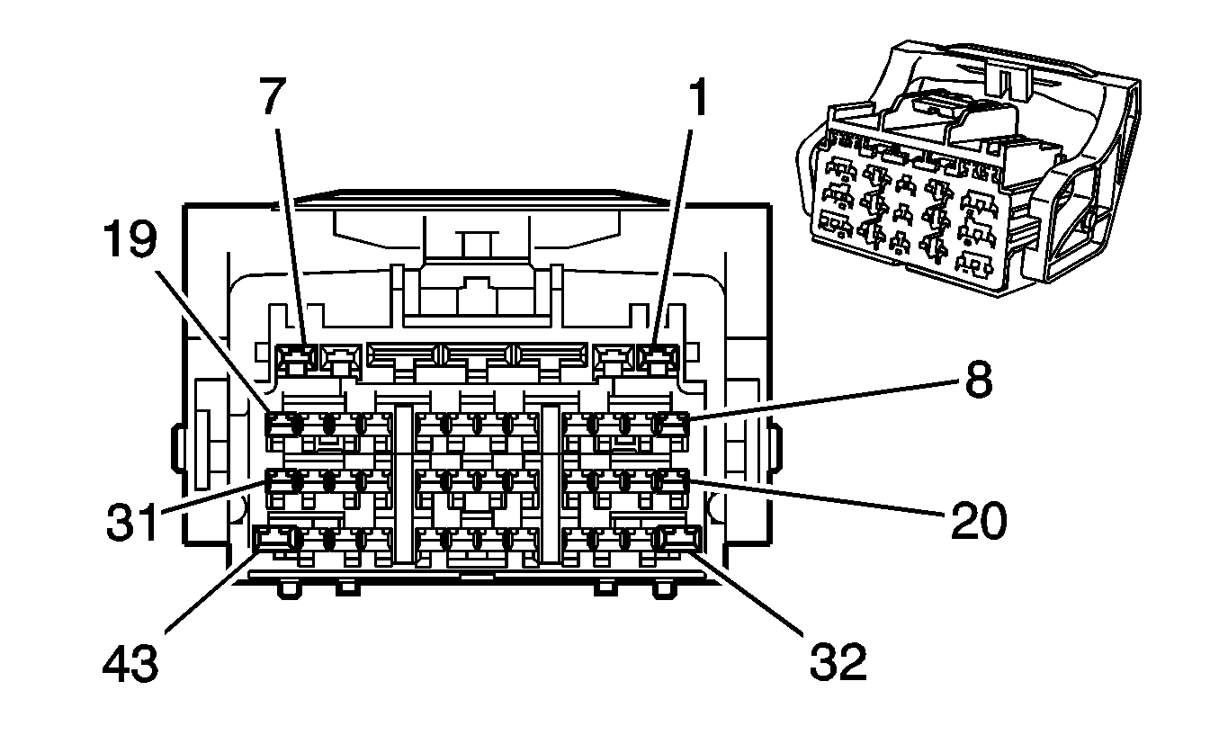
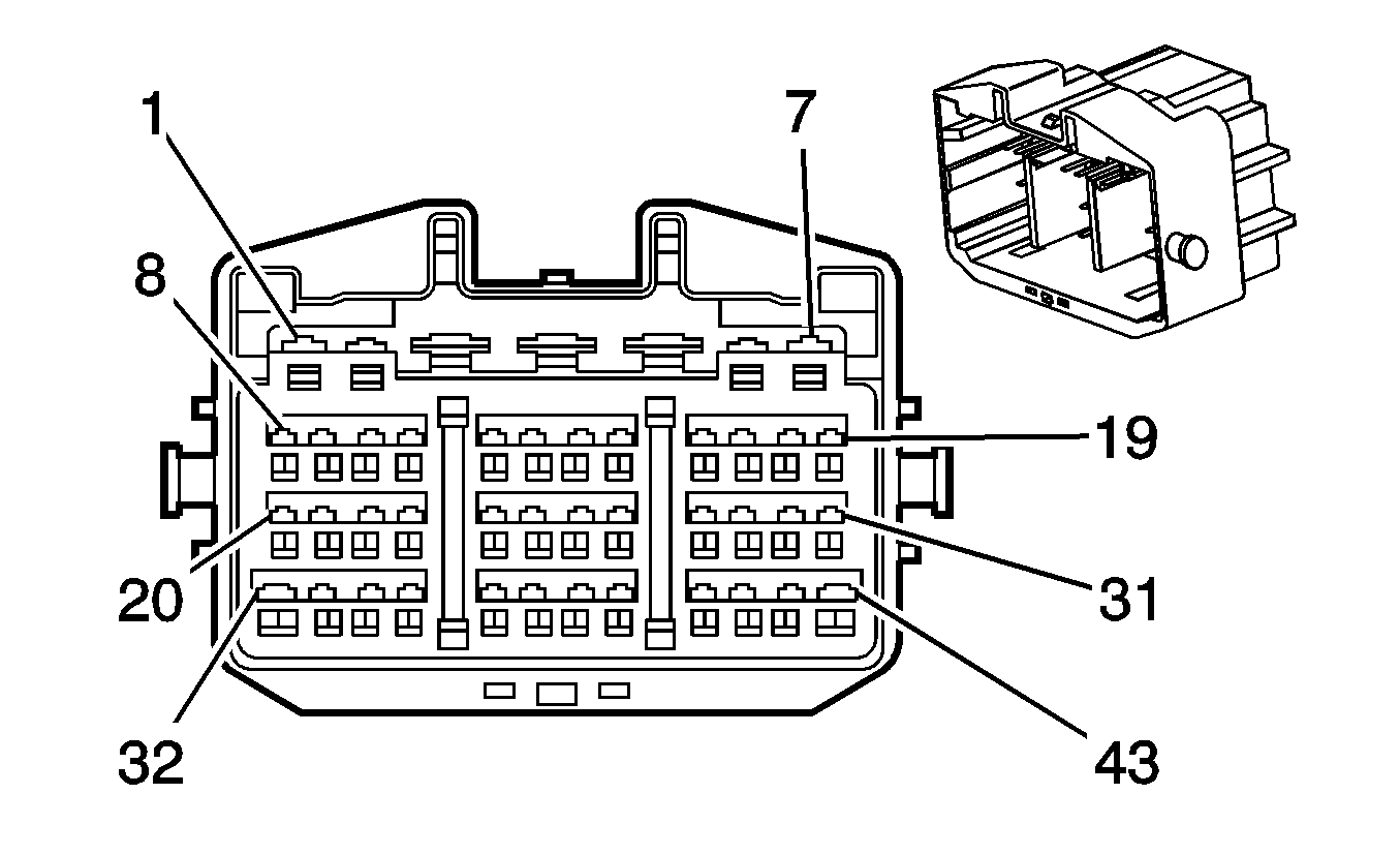
1 | YE | 5 | Crank Voltage (A/T) | 1 | YE | 5 | Crank Voltage (A/T) | ||||||||
PU | 6 | Starter Solenoid Crank Voltage (M/T) | YE | 6 | Starter Solenoid Crank Voltage (M/T) | ||||||||||
2 | YE | 343 | Accessory Voltage | 2 | YE | 343 | Accessory Voltage | ||||||||
3 | OG | 40 | Battery Positive Voltage | 3 | OG | 40 | Battery Positive Voltage | ||||||||
4 | RD | 1140 | Battery Positive Voltage | 4 | RD | 1140 | Battery Positive Voltage | ||||||||
5 | OG | 40 | Battery Positive Voltage | 5 | OG | 40 | Battery Positive Voltage | ||||||||
6 | PU | 92 | Windshield Wiper Motor High Speed | 6 | PU | 92 | Windshield Wiper Motor High Speed | ||||||||
7 | OG | 340 | Battery Positive Voltage | 7 | OG | 340 | Battery Positive Voltage | ||||||||
8 | PU | 420 | Brake Switch Signal | 8 | PU | 420 | Brake Switch Signal | ||||||||
9 | BN/WH | 2960 | Keyword Serial Data | 9 | BN/WH | 2960 | Keyword Serial Data | ||||||||
10 | L-BU | 20 | Stop Lamp Switch Signal | 10 | L-BU | 20 | Stop Lamp Switch Signal | ||||||||
11 | -- | -- | Not Used | 11 | -- | -- | Not Used | ||||||||
12 | D-BU | 46 | Right Rear Speaker Output (+) | 12 | D-BU | 46 | Right Rear Speaker Output (+) | ||||||||
13 | L-BU | 115 | Right Rear Speaker Output (-) | 13 | L-BU | 115 | Right Rear Speaker Output (-) | ||||||||
14 | PU | 719 | Low Reference | 14 | PU | 719 | Low Reference | ||||||||
15 | OG | 540 | Battery Positive Voltage | 15 | OG | 540 | Battery Positive Voltage | ||||||||
16 | TN | 201 | Left Front Speaker Output (+) | 16 | TN | 201 | Left Front Speaker Output (+) | ||||||||
17 | GY | 118 | Left Front Speaker Output (-) | 17 | GY | 118 | Left Front Speaker Output (-) | ||||||||
18 | TN/WH | 2500 | CAN High | 18 | TN/WH | 2500 | CAN High | ||||||||
19 | TN | 2501 | CAN Low | 19 | TN | 2501 | CAN Low | ||||||||
20 | WH/BK | 1164 | 5-Volt Reference | 20 | WH/BK | 1164 | 5-Volt Reference | ||||||||
21 | BN | 1271 | Low Reference | 21 | BN | 1271 | Low Reference | ||||||||
22 | L-BU | 1162 | APP Sensor 2 Signal | 22 | L-BU | 1162 | APP Sensor 2 Signal | ||||||||
23 | -- | -- | Not Used | 23 | -- | -- | Not Used | ||||||||
24 | PU | 1272 | Low Reference | 24 | PU | 1272 | Low Reference | ||||||||
25 | TN | 1274 | 5-Volt Reference | 25 | TN | 1274 | 5-Volt Reference | ||||||||
26 | D-BU | 1161 | APP Sensor 1 Signal | 26 | D-BU | 1161 | APP Sensor 1 Signal | ||||||||
27 | -- | -- | Not Used | 27 | -- | -- | Not Used | ||||||||
28 | GY/BK | 87 | Cruise Control Resume/Accel Switch Signal | 28 | GY/BK | 87 | Cruise Control Resume/Accel Switch Signal | ||||||||
29 | GY | 731 | Evaporator Temperature Sensor Signal | 29 | GY | 731 | Evaporator Temperature Sensor Signal | ||||||||
30 | GY | 397 | Cruise Control On Switch Signal | 30 | GY | 397 | Cruise Control On Switch Signal | ||||||||
31 | -- | -- | Not Used | 31 | -- | -- | Not Used | ||||||||
32 | D-GN | 95 | Windshield Wiper Motor Low Speed | 32 | D-GN | 95 | Windshield Wiper Motor Low Speed | ||||||||
33 | OG | 360 | Amplifier Control (WBM) | 33 | OG | 360 | Amplifier Control (WBM) | ||||||||
34 | D-BU | 84 | Cruise Control Set/Coast Switch Signal | 34 | D-BU | 84 | Cruise Control Set/Coast Switch Signal | ||||||||
35 | OG/BK | 1445 | Front Wiper Relay Control | 35 | OG/BK | 1445 | Front Wiper Relay Control | ||||||||
36 | WH/BK | 5043 | Keyword Serial Data | 36 | WH/BK | 5043 | Keyword Serial Data | ||||||||
37 | L-GN | 200 | Right Front Speaker Output (+) | 37 | L-GN | 200 | Right Front Speaker Output (+) | ||||||||
38 | D-GN | 117 | Right Front Speaker Output (-) | 38 | D-GN | 117 | Right Front Speaker Output (-) | ||||||||
39 | -- | -- | Not Used | 39 | -- | -- | Not Used | ||||||||
40 | BN | 199 | Left Rear Speaker Output (+) | 40 | BN | 199 | Left Rear Speaker Output (+) | ||||||||
41 | YE | 116 | Left Rear Speaker Output (-) | 41 | YE | 116 | Left Rear Speaker Output (-) | ||||||||
42 | -- | -- | Not Used | 42 | -- | -- | Not Used | ||||||||
43 | L-BU | 97 | Windshield Wiper Switch Mist/Off/Low Signal | 43 | L-BU | 97 | Windshield Wiper Switch Mist/Off/Low Signal | ||||||||
|
| ||||||||||||||
|---|---|---|---|---|---|---|---|---|---|---|---|---|---|---|---|
Connector Part Information |
| Connector Part Information |
| ||||||||||||
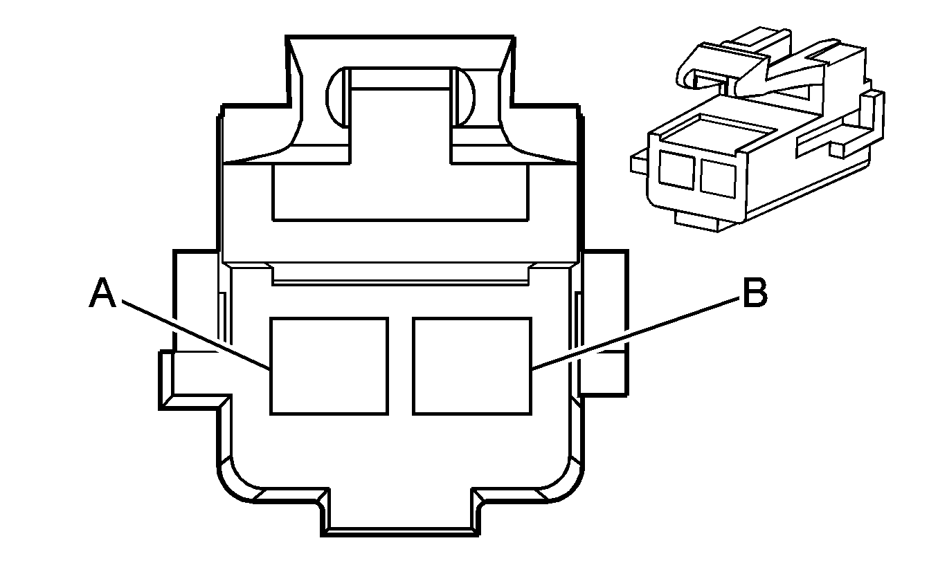
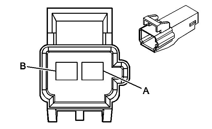
Pin | Wire Color | Circuit No. | Function | Pin | Wire Color | Circuit No. | Function | ||||||||
A | OG | 940 | Battery Positive Voltage | A | OG | 940 | Battery Positive Voltage | ||||||||
B | BK | 550 | Ground | B | BK | 550 | Ground | ||||||||
|

| ||||||||||||||
|---|---|---|---|---|---|---|---|---|---|---|---|---|---|---|---|
Connector Part Information |
| Connector Part Information |
| ||||||||||||
Pin | Wire Color | Circuit No. | Function | Pin | Wire Color | Circuit No. | Function | ||||||||
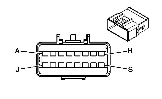
A | PU/WH | 3361 | Defrost Mode Valve Solenoid Control B | A | PU/WH | 3361 | Defrost Mode Valve Solenoid Control B | ||||||||
B | RD | 362 | Upper Mode Valve Solenoid Control A | B | RD | 362 | Upper Mode Valve Solenoid Control A | ||||||||
C | PU | 361 | Defrost Mode Valve Solenoid Control A | C | PU | 361 | Defrost Mode Valve Solenoid Control A | ||||||||
D | PK/WH | 1648 | Recirculation Door Control B | D | PK/WH | 1648 | Recirculation Door Control B | ||||||||
E | L-GN/BK | 1647 | Recirculation Door Control A | E | L-GN/BK | 1647 | Recirculation Door Control A | ||||||||
F | BK | 407 | Low Reference | F | BK | 407 | Low Reference | ||||||||
G | RD | 708 | Mode Door Position Signal | G | RD | 708 | Mode Door Position Signal | ||||||||
H | YE/BK | 1814 | Lower Mode Door Position Signal | H | YE/BK | 1814 | Lower Mode Door Position Signal | ||||||||
J | YE/BK | 713 | Defrost Mode Valve Position Sensor Signal | J | YE/BK | 713 | Defrost Mode Valve Position Sensor Signal | ||||||||
K | OG/WH | 3362 | Upper Mode Valve Solenoid Control B | K | OG/WH | 3362 | Upper Mode Valve Solenoid Control B | ||||||||
L | L-GN/WH | 366 | Lower Mode Valve Solenoid Control A | L | L-GN/WH | 366 | Lower Mode Valve Solenoid Control A | ||||||||
M | L-GN/BK | 3366 | Lower Mode Valve Solenoid Control B | M | L-GN/BK | 3366 | Lower Mode Valve Solenoid Control B | ||||||||
N | GY | 705 | 5-Volt Reference | N | GY | 705 | 5-Volt Reference | ||||||||
P-S | -- | -- | Not Used | P-S | -- | -- | Not Used | ||||||||
|
| ||||||||||||||
|---|---|---|---|---|---|---|---|---|---|---|---|---|---|---|---|
Connector Part Information |
| Connector Part Information |
| ||||||||||||
Pin | Wire Color | Circuit No. | Function | Pin | Wire Color | Circuit No. | Function | ||||||||
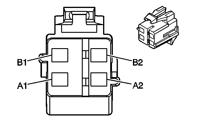
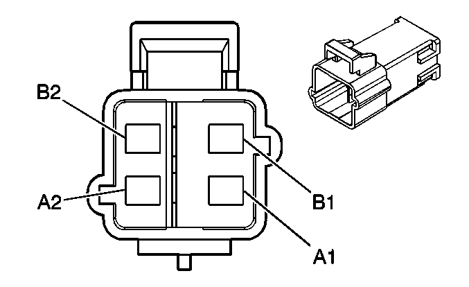
A1 | YE | 3025 | I/P Module - Stage 1 - High Control | A1 | YE | 3025 | I/P Module - Stage 1 - High Control | ||||||||
A2 | OG | 3024 | I/P Module - Stage 1 - Low Control | A2 | OG | 3024 | I/P Module - Stage 1 - Low Control | ||||||||
B1 | GY | 3027 | I/P Module - Stage 2 - High Control | B1 | GY | 3027 | I/P Module - Stage 2 - High Control | ||||||||
B2 | PU | 3026 | I/P Module - Stage 2 - Low Control | B2 | PU | 3026 | I/P Module - Stage 2 - Low Control | ||||||||
|
| ||||||||||||||
|---|---|---|---|---|---|---|---|---|---|---|---|---|---|---|---|
Connector Part Information |
| Connector Part Information |
| ||||||||||||
Pin | Wire Color | Circuit No. | Function | Pin | Wire Color | Circuit No. | Function | ||||||||
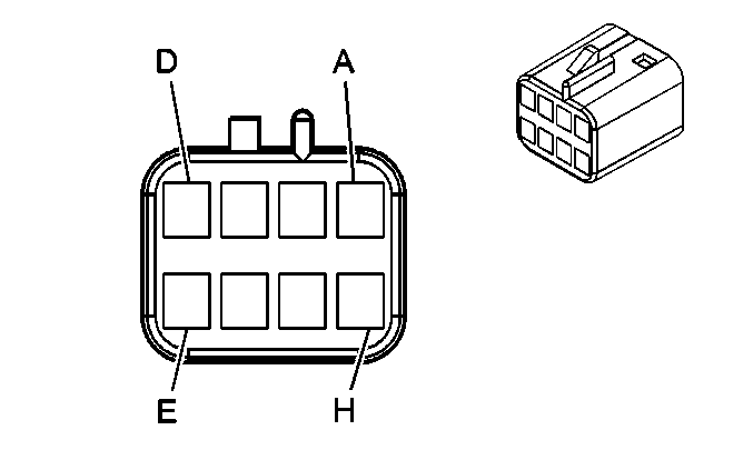
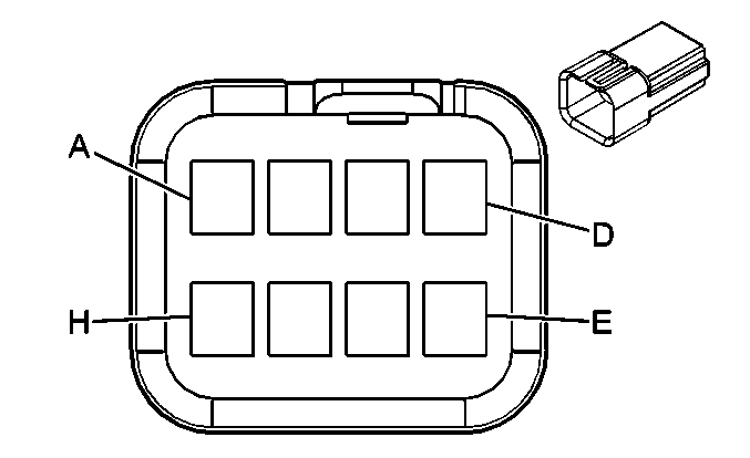
A | WH | 156 | Courtesy Lamp Switch Signal | A | WH | 156 | Courtesy Lamp Switch Signal | ||||||||
B | BK | 750 | Ground | B | BK | 750 | Ground | ||||||||
C | OG | 1732 | Courtesy Lamps Supply Voltage | C | OG | 1732 | Courtesy Lamps Supply Voltage | ||||||||
D | YE | 43 | Ignition 1 Voltage | D | YE | 43 | Ignition 1 Voltage | ||||||||
E | OG | 580 | Accessory Voltage (CF5) | E | OG | 580 | Accessory Voltage (CF5) | ||||||||
F | L-GN | 24 | Backup Lamp Supply Voltage (HAA/HCO) | F | L-GN | 24 | Backup Lamp Supply Voltage (HAA/HCO) | ||||||||
G | GY | 157 | Courtesy Lamps Control | G | GY | 157 | Courtesy Lamps Control | ||||||||
H | BK | 750 | Ground (CF5) | H | BK | 750 | Ground (CF5) | ||||||||
J | L-GN/BK | 735 | Ambient Air Temperature Sensor Signal (HAA/HCO) | J | L-GN/BK | 735 | Ambient Air Temperature Sensor Signal (HAA/HCO) | ||||||||
K | GY | 720 | Low Reference (HAA/HCO) | K | GY | 720 | Low Reference (HAA/HCO) | ||||||||
|
| ||||||||||||||
|---|---|---|---|---|---|---|---|---|---|---|---|---|---|---|---|
Connector Part Information |
| Connector Part Information |
| ||||||||||||
Pin | Wire Color | Circuit No. | Function | Pin | Wire Color | Circuit No. | Function | ||||||||
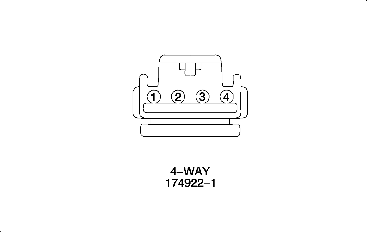
A | BN | 100 | Sunroof Switch Open Signal | A | BN | 100 | Sunroof Switch Open Signal | ||||||||
B | D-GN | 2074 | Sunroof Switch Express Signal | B | D-GN | 2074 | Sunroof Switch Express Signal | ||||||||
C | OG/BK | 144 | Sunroof Switch Open Vent Signal | C | OG/BK | 144 | Sunroof Switch Open Vent Signal | ||||||||
D | D-BU | 128 | Low Reference | D | D-BU | 128 | Low Reference | ||||||||
E | OG | 580 | Accessory Voltage | E | OG | 580 | Accessory Voltage | ||||||||
F | BK | 750 | Ground | F | BK | 750 | Ground | ||||||||
G-H | -- | -- | Not Used | G-H | -- | -- | Not Used | ||||||||

| |||||||||||||||
|---|---|---|---|---|---|---|---|---|---|---|---|---|---|---|---|
Connector Part Information |
| Connector Part Information |
| ||||||||||||
Pin | Wire Color | Circuit No. | Function | Pin | Wire Color | Circuit No. | Function | ||||||||
A | YE/BK | 2516 | Keypad Green LED Signal | A | YE/BK | 2516 | Keypad Green LED Signal | ||||||||
B | L-GN/BK | 2515 | Keypad Supply Signal | B | L-GN/BK | 2515 | Keypad Supply Signal | ||||||||
C | D-GN/WH | 2514 | Keypad Signal | C | D-GN/WH | 2514 | Keypad Signal | ||||||||
D | BN/WH | 2517 | Keypad Red LED Signal | D | BN/WH | 2517 | Keypad Red LED Signal | ||||||||
E | GY | 655 | Cellular Microphone Signal | E | GY | 655 | Cellular Microphone Signal | ||||||||
F | BARE | 654 | Cellular Microphone Low Reference | F | BARE | 654 | Cellular Microphone Low Reference | ||||||||
G-H | -- | -- | Not Used | G-H | -- | -- | Not Used | ||||||||
|

| ||||||||||||||
|---|---|---|---|---|---|---|---|---|---|---|---|---|---|---|---|
Connector Part Information |
| Connector Part Information |
| ||||||||||||
Pin | Wire Color | Circuit No. | Function | Pin | Wire Color | Circuit No. | Function | ||||||||
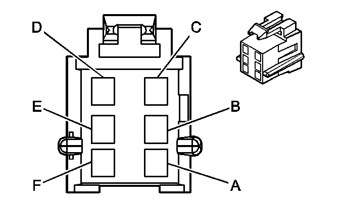
1 | TN/WH | 816 | A/T Shift Lock Solenoid Supply Voltage | 1 | WH | 816 | A/T Shift Lock Solenoid Supply Voltage | ||||||||
2 | PK | 139 | Ignition 1 Voltage | 2 | PK | 139 | Ignition 1 Voltage | ||||||||
3 | GY | 8 | Instrument Panel Lamp Supply Voltage | 3 | GY | 8 | Instrument Panel Lamp Supply Voltage | ||||||||
4 | BK | 550 | Ground | 4 | BK | 550 | Ground | ||||||||
|
| ||||||||||||||
|---|---|---|---|---|---|---|---|---|---|---|---|---|---|---|---|
Connector Part Information |
| Connector Part Information |
| ||||||||||||
Pin | Wire Color | Circuit No. | Function | Pin | Wire Color | Circuit No. | Function | ||||||||
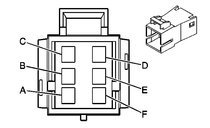
A | OG | 1540 | Battery Positive Voltage | A | OG | 1540 | Battery Positive Voltage | ||||||||
B | L-BU | 1462 | Heated Seat Switch Signal | B | L-BU | 1462 | Heated Seat Switch Signal | ||||||||
C | PK | 1501 | Driver Heated Seat High/Low Signal | C | PK | 1501 | Driver Heated Seat High/Low Signal | ||||||||
D | BK | 650 | Ground | D | BK | 650 | Ground | ||||||||
E | OG | 1240 | Battery Positive Voltage | E | OG | 1240 | Battery Positive Voltage | ||||||||
F | BK | 650 | Ground | F | BK | 650 | Ground | ||||||||

| |||||||||||||||
|---|---|---|---|---|---|---|---|---|---|---|---|---|---|---|---|
Connector Part Information |
| Connector Part Information |
| ||||||||||||
Pin | Wire Color | Circuit No. | Function | Pin | Wire Color | Circuit No. | Function | ||||||||
A | OG | 1540 | Battery Positive Voltage | A | OG | 1540 | Battery Positive Voltage | ||||||||
B | L-BU/BK | 1505 | Heated Seat Switch Signal | B | L-BU | 1505 | Heated Seat Switch Signal | ||||||||
C | PK/BK | 1503 | Passenger Heated Seat High/Low Signal | C | PK | 1503 | Passenger Heated Seat High/Low Signal | ||||||||
D | BK | 650 | Ground | D | BK | 650 | Ground | ||||||||
|
| ||||||||||||||
|---|---|---|---|---|---|---|---|---|---|---|---|---|---|---|---|
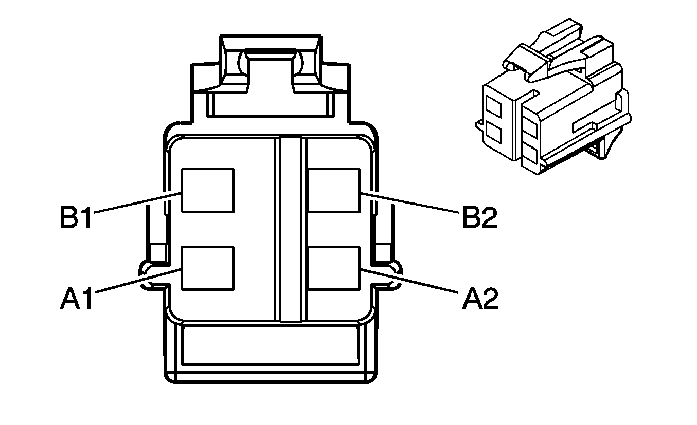
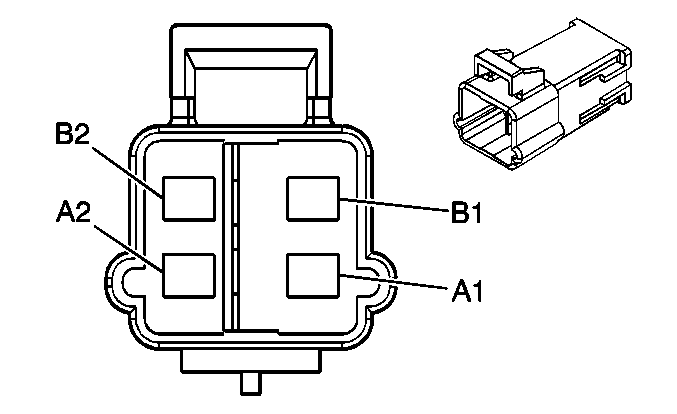
Connector Part Information |
| Connector Part Information |
| ||||||||||||
Pin | Wire Color | Circuit No. | Function | Pin | Wire Color | Circuit No. | Function | ||||||||
A1 | YE | 2131 | Left SIS Module Voltage | A1 | YE | 2131 | Left SIS Module Voltage | ||||||||
A2 | WH | 2132 | Left SIS Module Signal | A2 | WH | 2132 | Left SIS Module Signal | ||||||||
B1 | TN | 2133 | Right SIS Module Voltage | B1 | TN | 2133 | Right SIS Module Voltage | ||||||||
B2 | D-GN | 2134 | Right SIS Module Signal | B2 | D-GN | 2134 | Right SIS Module Signal | ||||||||
|
| ||||||||||||||
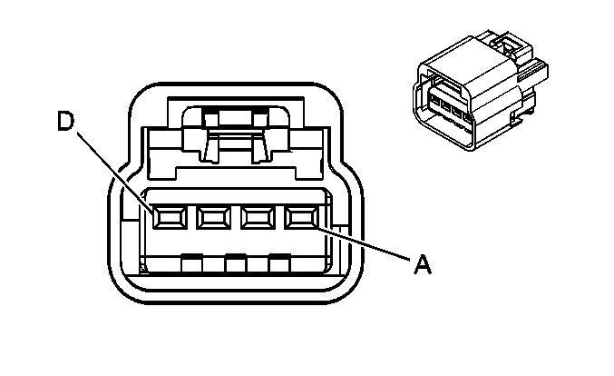
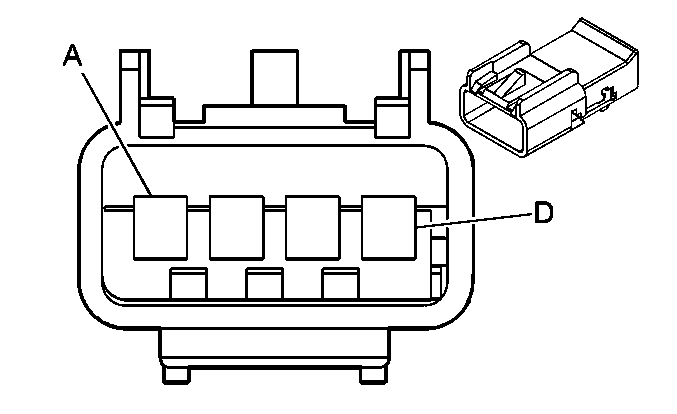
|---|---|---|---|---|---|---|---|---|---|---|---|---|---|---|---|
Connector Part Information |
| Connector Part Information |
| ||||||||||||
Pin | Wire Color | Circuit No. | Function | Pin | Wire Color | Circuit No. | Function | ||||||||
A | YE | 2131 | Left SIS Module Voltage | A | YE | 2131 | Left SIS Module Voltage | ||||||||
B | WH | 2132 | Left SIS Module Signal | B | WH | 2132 | Left SIS Module Signal | ||||||||
C | TN | 2133 | Right SIS Module Voltage | C | TN | 2133 | Right SIS Module Voltage | ||||||||
D | D-GN | 2134 | Right SIS Module Signal | D | D-GN | 2134 | Right SIS Module Signal | ||||||||

|

| ||||||||||||||
|---|---|---|---|---|---|---|---|---|---|---|---|---|---|---|---|
Connector Part Information |
| Connector Part Information |
| ||||||||||||
Pin | Wire Color | Circuit No. | Function | Pin | Wire Color | Circuit No. | Function | ||||||||
A1 | BK/WH | 2135 | RF Side Impact Module High Control | A1 | BK/WH | 2135 | RF Side Impact Module High Control | ||||||||
A2 | L-GN | 2136 | RF Side Impact Module Low Control | A2 | L-GN | 2136 | RF Side Impact Module Low Control | ||||||||
B1 | BN | 2137 | LF Side Impact Module High Control | B1 | BN | 2137 | LF Side Impact Module High Control | ||||||||
B2 | YE/BK | 2138 | LF Side Impact Module Low Control | B2 | YE/BK | 2138 | LF Side Impact Module Low Control | ||||||||
|
| ||||||||||||||||
|---|---|---|---|---|---|---|---|---|---|---|---|---|---|---|---|---|---|
Connector Part Information |
| Connector Part Information |
| ||||||||||||||
Pin | Wire Color | Circuit No. | Function | Pin | Wire Color | Circuit No. | Function | ||||||||||
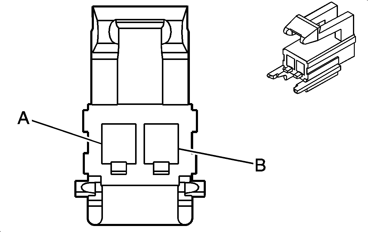
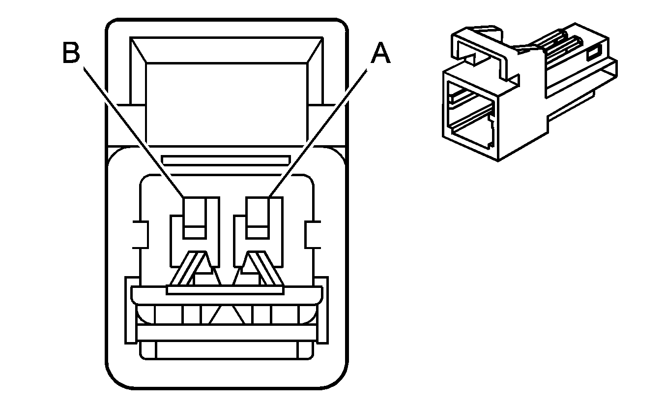
A | TN/WH | 2118 | Left Seat Belt Pretesnioner Control - High | A | -- | 2118 | Left Seat Belt Pretesnioner Control - High | ||||||||||
B | OG/BK | 2119 | Left Seat Belt Pretesnioner Control - Low | B | -- | 2119 | Left Seat Belt Pretesnioner Control - Low | ||||||||||

|

| ||||||||||||||||
|---|---|---|---|---|---|---|---|---|---|---|---|---|---|---|---|---|---|
Connector Part Information |
| Connector Part Information |
| ||||||||||||||
Pin | Wire Color | Circuit No. | Function | Pin | Wire Color | Circuit No. | Function | ||||||||||
A | L-GN | 2116 | Right Seat Belt Pretesnioner Control - High | A | -- | 2116 | Right Seat Belt Pretesnioner Control - High | ||||||||||
B | OG | 2117 | Right Seat Belt Pretesnioner Control - Low | B | -- | 2117 | Right Seat Belt Pretesnioner Control - Low | ||||||||||
|
| ||||||||||||||
|---|---|---|---|---|---|---|---|---|---|---|---|---|---|---|---|
Connector Part Information |
| Connector Part Information |
| ||||||||||||
Pin | Wire Color | Circuit No. | Function | Pin | Wire Color | Circuit No. | Function | ||||||||
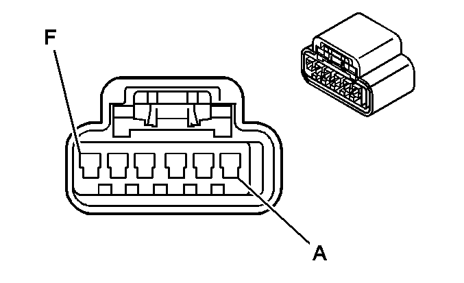
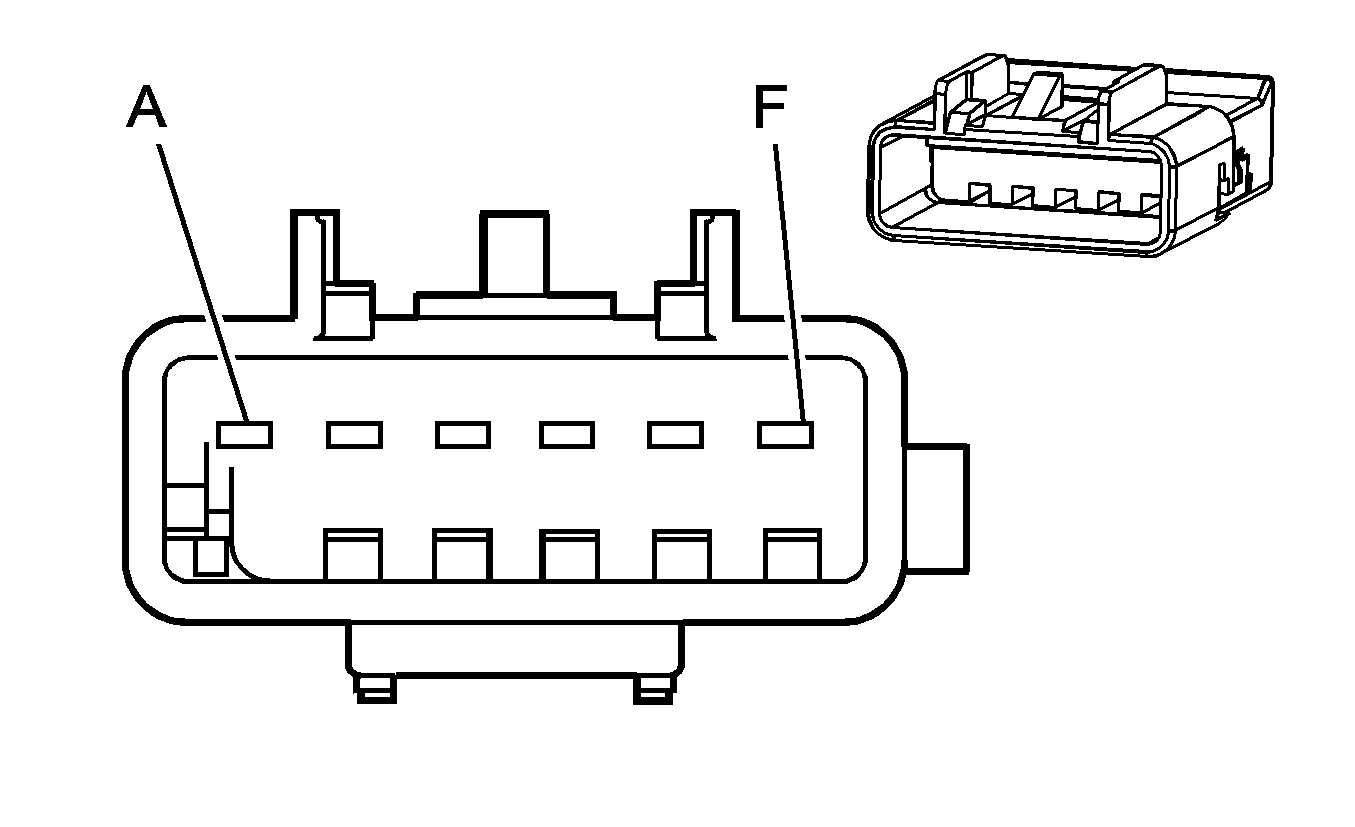
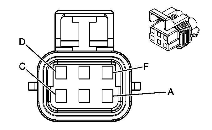
A | TN/WH | 2118 | Left Seat Belt Pretesnioner Control - High | A | TN/WH | 2118 | Left Seat Belt Pretesnioner Control - High | ||||||||
B | OG/BK | 2119 | Left Seat Belt Pretesnioner Control - Low | B | OG/BK | 2119 | Left Seat Belt Pretesnioner Control - Low | ||||||||
C-D | -- | -- | Not Used | C-D | -- | -- | Not Used | ||||||||
E | L-GN | 2116 | Right Seat Belt Pretesnioner Control - High | E | L-GN | 2116 | Right Seat Belt Pretesnioner Control - High | ||||||||
F | OG | 2117 | Right Seat Belt Pretesnioner Control - Low | F | OG | 2117 | Right Seat Belt Pretesnioner Control - Low | ||||||||
|
| ||||||||||||||
|---|---|---|---|---|---|---|---|---|---|---|---|---|---|---|---|
Connector Part Information |
| Connector Part Information |
| ||||||||||||
Pin | Wire Color | Circuit No. | Function | Pin | Wire Color | Circuit No. | Function | ||||||||
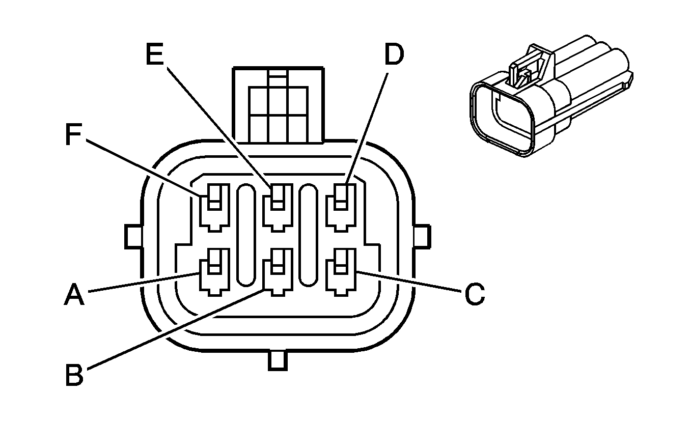
A | YE | 18 | Left Rear Stop/Turn Lamp Supply Voltage | A | D-BU | 18 | Left Rear Stop/Turn Lamp Supply Voltage | ||||||||
B | BN | 9 | Park Lamp Supply Voltage | B | BN | 9 | Park Lamp Supply Voltage | ||||||||
C | BK | 750 | Ground | C | BK | 750 | Ground | ||||||||
D | L-GN | 24 | Backup Lamp Switch Signal | D | L-GN | 24 | Backup Lamp Switch Signal | ||||||||
E | -- | -- | Not Used | E | -- | -- | Not Used | ||||||||
F | L-BU | 20 | Stop Lamp Switch Signal | F | L-BU | 20 | Stop Lamp Switch Signal | ||||||||

|

| ||||||||||||||
|---|---|---|---|---|---|---|---|---|---|---|---|---|---|---|---|
Connector Part Information |
| Connector Part Information |
| ||||||||||||
Pin | Wire Color | Circuit No. | Function | Pin | Wire Color | Circuit No. | Function | ||||||||
A | D-GN | 19 | Right Rear Stop/Turn Lamp Supply Voltage | A | D-BU | 19 | Right Rear Stop/Turn Lamp Supply Voltage | ||||||||
B | BN | 9 | Park Lamp Supply Voltage | B | BN | 9 | Park Lamp Supply Voltage | ||||||||
C | BK | 850 | Ground | C | BK | 850 | Ground | ||||||||
D | L-GN | 24 | Backup Lamp Switch Signal | D | L-GN | 24 | Backup Lamp Switch Signal | ||||||||
E | -- | -- | Not Used | E | -- | -- | Not Used | ||||||||
F | L-BU | 20 | Stop Lamp Switch Signal | F | L-BU | 20 | Stop Lamp Switch Signal | ||||||||

|

| ||||||||||||||
|---|---|---|---|---|---|---|---|---|---|---|---|---|---|---|---|
Connector Part Information |
| Connector Part Information |
| ||||||||||||
Pin | Wire Color | Circuit No. | Function | Pin | Wire Color | Circuit No. | Function | ||||||||
A | BN | 9 | Park Lamp Supply Voltage | A | BN | 9 | Park Lamp Supply Voltage | ||||||||
B | OG | 1732 | Courtesy Lamps Supply Voltage | B | OG | 1732 | Courtesy Lamps Supply Voltage | ||||||||
C | L-BU | 20 | Stop Lamp Switch Signal | C | L-BU | 20 | Stop Lamp Switch Signal | ||||||||
D | GY | 295 | Door Lock Actuator Lock Control | D | GY | 295 | Door Lock Actuator Lock Control | ||||||||
E | TN | 294 | Door Lock Actuator Unlock Control | E | TN | 294 | Door Lock Actuator Unlock Control | ||||||||
F | YE | 143 | Accessory Voltage | F | YE | 143 | Accessory Voltage | ||||||||
G | WH | 393 | Rear Window Wiper Motor Control | G | WH | 393 | Rear Window Wiper Motor Control | ||||||||
H | BK | 650 | Ground | H | BK | 650 | Ground | ||||||||
J | GY | 157 | Courtesy Lamp Control | J | GY | 157 | Courtesy Lamp Control | ||||||||
K | RD/BK | 744 | Liftgate Ajar Switch Signal | K | RD/BK | 744 | Liftgate Ajar Switch Signal | ||||||||
|
| ||||||||||||||
|---|---|---|---|---|---|---|---|---|---|---|---|---|---|---|---|
Connector Part Information |
| Connector Part Information |
| ||||||||||||
Pin | Wire Color | Circuit No. | Function | Pin | Wire Color | Circuit No. | Function | ||||||||
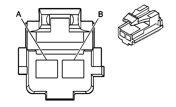
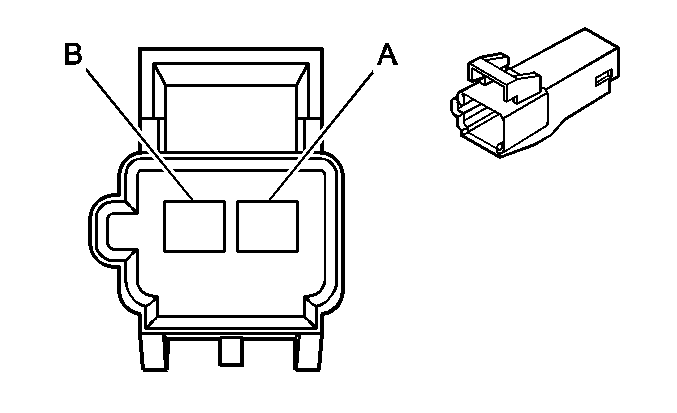
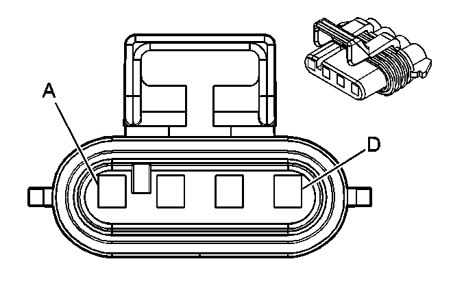
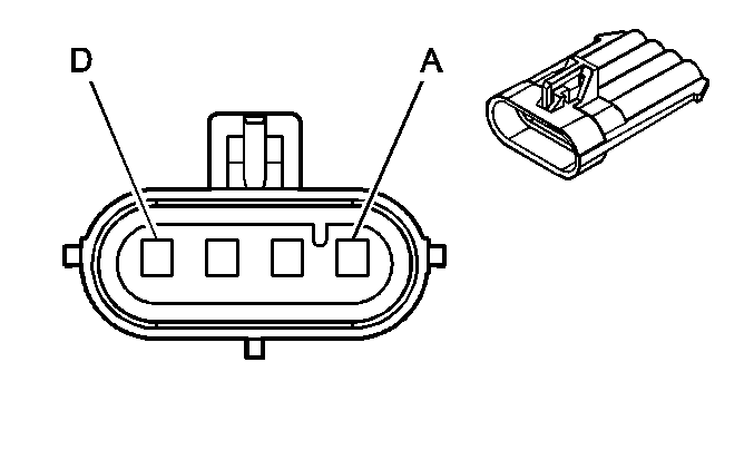
A | BK | 293 | Rear Defog Element Supply Voltage | A | PU | 293 | Rear Defog Element Supply Voltage | ||||||||
B | BK | 750 | Ground | B | BK | 750 | Ground | ||||||||
|
| ||||||||||||||
|---|---|---|---|---|---|---|---|---|---|---|---|---|---|---|---|
Connector Part Information |
| Connector Part Information |
| ||||||||||||
Pin | Wire Color | Circuit No. | Function | Pin | Wire Color | Circuit No. | Function | ||||||||
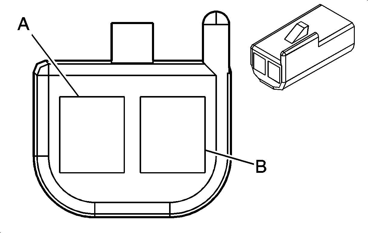
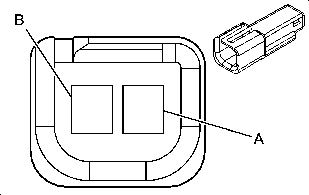
A | BN | 882 | RR WSS Signal | A | BN | 882 | RR WSS Signal | ||||||||
B | WH | 883 | RR WSS Low Ref | B | WH | 883 | RR WSS Low Ref | ||||||||
C | BK | 884 | LR WSS Signal | C | BK | 884 | LR WSS Signal | ||||||||
D | RD | 885 | LR WSS Low Ref | D | RD | 885 | LR WSS Low Ref | ||||||||
|
| ||||||||||||||
|---|---|---|---|---|---|---|---|---|---|---|---|---|---|---|---|
Connector Part Information |
| Connector Part Information |
| ||||||||||||
Pin | Wire Color | Circuit No. | Function | Pin | Wire Color | Circuit No. | Function | ||||||||
A | BK | 650 | Ground | A | BK | 650 | Ground | ||||||||
B | WH | 9 | Park Lamp Supply Voltage | B | BN | 9 | Park Lamp Supply Voltage | ||||||||

| |||||||||||||||
|---|---|---|---|---|---|---|---|---|---|---|---|---|---|---|---|
Connector Part Information |
| Connector Part Information |
| ||||||||||||
Pin | Wire Color | Circuit No. | Function | Pin | Wire Color | Circuit No. | Function | ||||||||
A | GY | 120 | Fuel Pump Supply Voltage | A | GY | 120 | Fuel Pump Supply Voltage | ||||||||
B | BK | 850 | Ground | B | BK | 850 | Ground | ||||||||
C | PU | 1589 | Fuel Level Sensor Signal | C | PU | 1589 | Fuel Level Sensor Signal | ||||||||
D | -- | -- | Not Used (For Diagnostics) | D | D-BU | 930 | Fuel Level Sensor Signal | ||||||||
E | GY | 2709 | 5-Volt Reference | E | GY | 2709 | 5-Volt Reference | ||||||||
F | D-GN | 890 | Fuel Tank Pressure Sensor Signal | F | D-GN | 890 | Fuel Tank Pressure Sensor Signal | ||||||||
G | BK | 2759 | Low Reference | G | BK | 2759 | Low Reference | ||||||||
H | BK | 2759 | Low Reference (L61) | H | BK | 2759 | Low Reference | ||||||||
H | BN/WH | 6281 | Low Reference (L66) | ||||||||||||
J | WH | 5291 | Ignition 1 Voltage | J | WH | 5291 | Ignition 1 Voltage | ||||||||
K | WH | 1310 | EVAP Canister Vent Solenoid Control | K | WH | 1310 | EVAP Canister Vent Solenoid Control | ||||||||
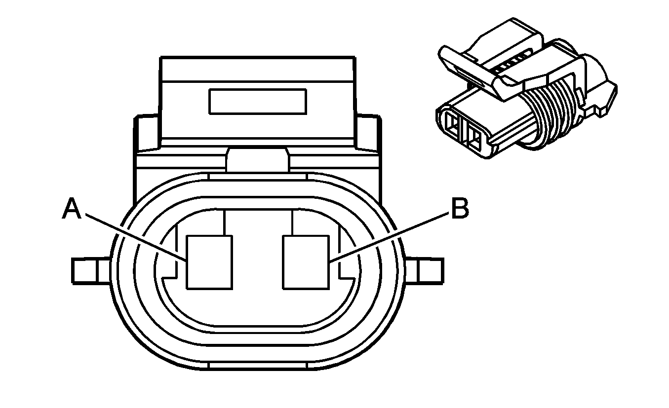
|
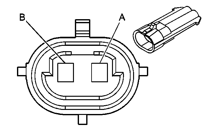
| ||||||||||||||
|---|---|---|---|---|---|---|---|---|---|---|---|---|---|---|---|
Connector Part Information |
| Connector Part Information |
| ||||||||||||
Pin | Wire Color | Circuit No. | Function | Pin | Wire Color | Circuit No. | Function | ||||||||
A | GY | 295 | Door Lock Actuator Lock Control | A | GY | 295 | Door Lock Actuator Lock Control | ||||||||
B | TN | 294 | Door Lock Actuator Unlock Control | B | TN | 294 | Door Lock Actuator Unlock Control | ||||||||

|

| ||||||||||||||
|---|---|---|---|---|---|---|---|---|---|---|---|---|---|---|---|
Connector Part Information |
| Connector Part Information |
| ||||||||||||
Pin | Wire Color | Circuit No. | Function | Pin | Wire Color | Circuit No. | Function | ||||||||
A | GY | 295 | Door Lock Actuator Lock Control | A | GY | 295 | Door Lock Actuator Lock Control | ||||||||
B | TN | 294 | Door Lock Actuator Unlock Control | B | TN | 294 | Door Lock Actuator Unlock Control | ||||||||
