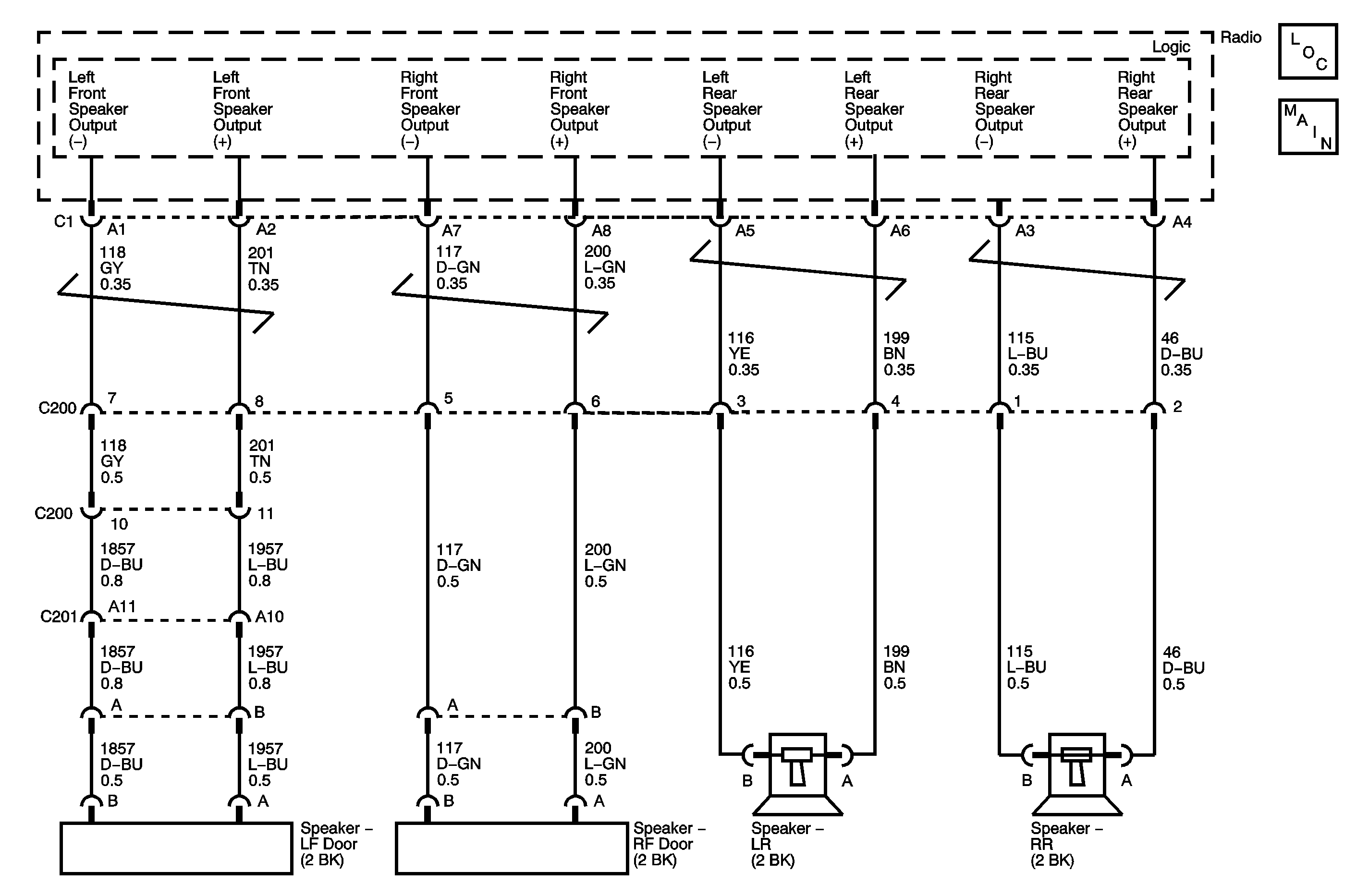
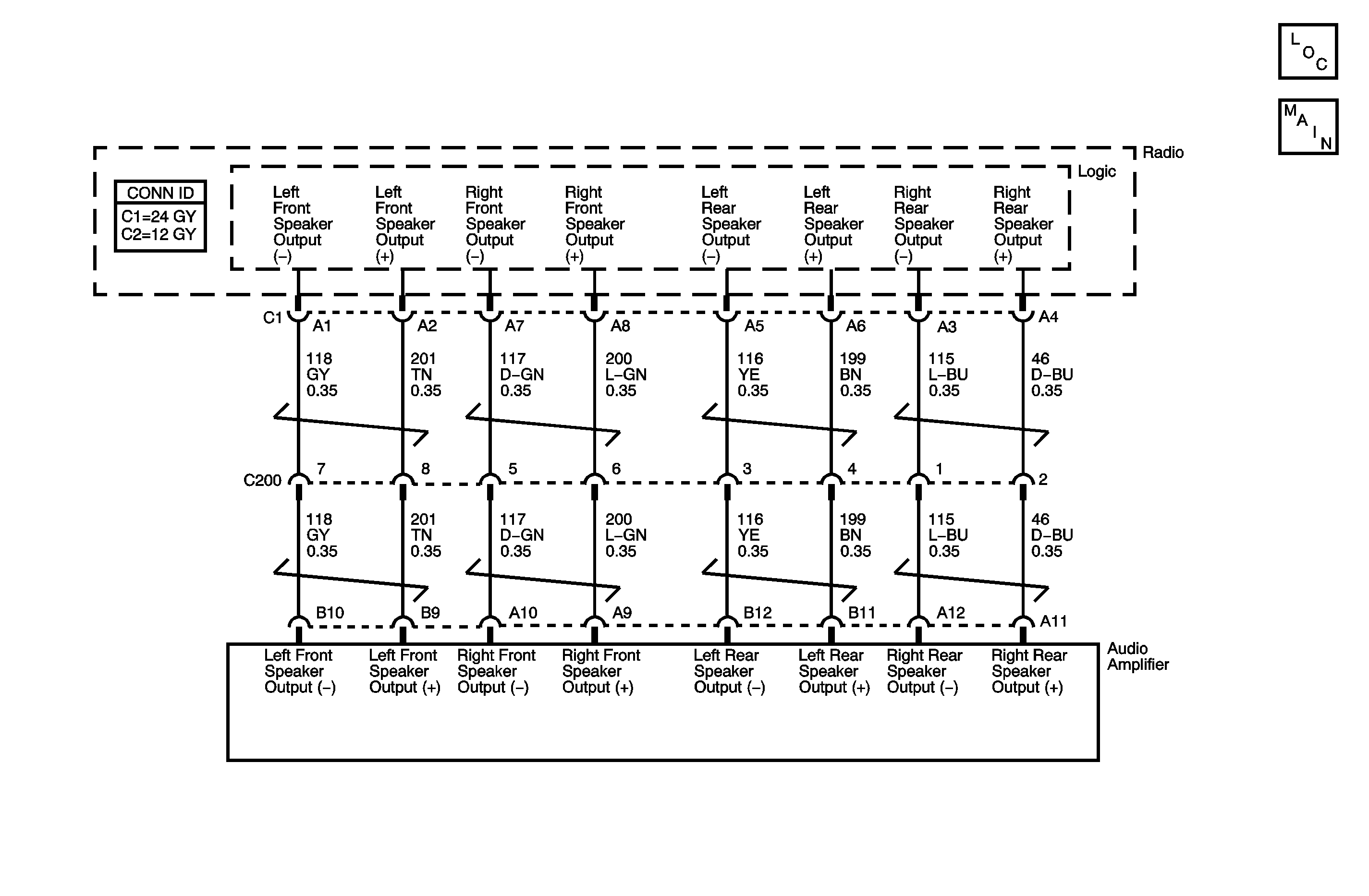
DTC B1030, B1040, B1050, or B1060 With RPO WBM

Circuit Description
When the radio is set at minimum volume, the plus (+) and minus (-) speaker outputs are approximately 5-6 volts measured to vehicle ground. As the volume increases, the plus and minus change to create a voltage difference between each other. This drives the voice coil of the speaker producing sound.
DTC Descriptors
This diagnostic procedure supports the following DTCs:
| • | DTC B1030 LF Audio Output (-) Circuit |
| • | DTC B1040 RF Audio Output (-) Circuit |
| • | DTC B1050 LR Audio Output (-) Circuit |
| • | DTC B1060 RR Audio Output (-) Circuit |
This vehicle has DTCs which include DTC Symptoms. For more information on DTC Symptoms, refer to DTC Symptom Description in Vehicle DTC Information.
DTC Symptom | DTC Symptom Descriptor |
|---|---|
01 | Short to Battery |
02 | Short to Ground |
04 | Open Circuit |
Conditions for Running the DTC
B1030-B1060 01, 02, and 04
The following are conditions that must be present in order for the radio to enable the diagnostics.
| • | The vehicle power mode is ACCESSORY, RUN, or retained accessory power (RAP). |
| • | The system voltage is at least 9 volts and no more than 16 volts. |
| • | All the above conditions are present for greater than 250 milliseconds. |
Conditions for Setting the DTC
The following conditions are present for 250 milliseconds or longer:
B1030-B1060 01
One of the speaker negative output circuits is shorted to battery.
B1030-B1060 02
The speaker negative output circuit is shorted to ground.
B1030-B1060 04
The speaker negative output circuit is open.
Action Taken When the DTC Sets
The radio disables the audio output to the speaker with the current fault.
Conditions for Clearing the DTC
| • | The Conditions for Setting the DTC are no longer present. |
| • | A history DTC clears after 100 malfunction-free ignition cycles. |
| • | The radio receives the clear code command from the scan tool. |
Test Description
The numbers below refer to the step numbers on the diagnostic table.
Step | Action | Yes | No |
|---|---|---|---|
Schematic Reference: Radio/Audio System Schematics Connector End View Reference: Entertainment Connector End Views | |||
1 | Did you perform the Diagnostic System Check - Vehicle? | Go to Step 2 | Go to Diagnostic System Check - Vehicle in Vehicle DTC Information |
Does the scan tool indicate that DTC B1030, B1040, B1050, or B1060 is current? | Go to Step 3 | Go to Testing for Intermittent Conditions and Poor Connections in Wiring Systems | |
Test the affected speaker output channel from the radio to the speaker for a short to ground, short to voltage, or open circuit. Refer to Circuit Testing and Wiring Repairs in Wiring Systems. Did you find and correct the condition? | Go to Step 6 | Go to Step 4 | |
4 | Inspect for poor connections at the harness connector of the radio. Refer to Testing for Intermittent Conditions and Poor Connections and Connector Repairs in Wiring Systems. Did you find and correct the condition? | Go to Step 6 | Go to Step 5 |
5 | Replace the radio. Refer to Control Module References in Computer/Integrating Systems for replacement, setup, and programming. Did you complete the replacement? | Go to Step 6 | -- |
6 | Operate the system in order to verify the repair. Did you correct the condition? | System OK | Go to Step 2 |
DTC B1030, B1040, B1050, or B1060 Without RPO WBM

Circuit Description
When the radio is set at minimum volume, the plus (+) and minus (-) speaker outputs are approximately 5-6 volts measured to vehicle ground. As the volume increases, the plus and minus change to create a voltage difference between each other. This drives the voice coil of the speaker producing sound.
DTC Descriptors
This diagnostic procedure supports the following DTCs:
| • | DTC B1030 LF Audio Output (-) Circuit |
| • | DTC B1040 RF Audio Output (-) Circuit |
| • | DTC B1050 LR Audio Output (-) Circuit |
| • | DTC B1060 RR Audio Output (-) Circuit |
This vehicle has DTCs which include DTC Symptoms. For more information on DTC Symptoms, refer to DTC Symptom Description in Vehicle DTC Information.
DTC Symptom | DTC Symptom Descriptor |
|---|---|
01 | Short to Battery |
02 | Short to Ground |
04 | Open Circuit |
Conditions for Running the DTC
B1030-B1060 01, 02, and 04
The following are conditions that must be present in order for the radio to enable the diagnostics.
| • | The vehicle power mode is ACCESSORY, RUN, or retained accessory power (RAP). |
| • | The system voltage is at least 9 volts and no more than 16 volts. |
| • | All the above conditions are present for greater than 250 milliseconds. |
Conditions for Setting the DTC
The following conditions are present for 250 milliseconds or longer:
B1030-B1060 01
One of the speaker negative output circuits is shorted to battery.
B1030-B1060 02
The speaker negative output circuit is shorted to ground.
B1030-B1060 04
The speaker negative output circuit is open.
Action Taken When the DTC Sets
The radio disables the audio output to the speaker with the current fault.
Conditions for Clearing the DTC
| • | The Conditions for Setting the DTC are no longer present. |
| • | A history DTC clears after 100 malfunction-free ignition cycles. |
| • | The radio receives the clear code command from the scan tool. |
Test Description
The numbers below refer to the step numbers on the diagnostic table.
Step | Action | Yes | No |
|---|---|---|---|
Schematic Reference: Radio/Audio System Schematics Connector End View Reference: Entertainment Connector End Views | |||
1 | Did you perform the Diagnostic System Check - Vehicle? | Go to Step 2 | Go to Diagnostic System Check - Vehicle in Vehicle DTC Information |
Does the scan tool indicate that DTC B1030, B1040, B1050, or B1060 is current? | Go to Step 3 | Go to Testing for Intermittent Conditions and Poor Connections in Wiring Systems | |
Test the affected speaker output channel from the radio to the amplifier for a short to ground, short to voltage, or open circuit. Refer to Circuit Testing and Wiring Repairs in Wiring Systems. Did you find and correct the condition? | Go to Step 6 | Go to Step 4 | |
4 | Inspect for poor connections at the harness connector of the radio. Refer to Testing for Intermittent Conditions and Poor Connections and Connector Repairs in Wiring Systems. Did you find and correct the condition? | Go to Step 6 | Go to Step 5 |
5 | Replace the radio. Refer to Control Module References in Computer/Integrating Systems for replacement, setup, and programming. Did you complete the replacement? | Go to Step 6 | -- |
6 | Operate the system in order to verify the repair. Did you correct the condition? | System OK | Go to Step 2 |
