Tools Required
| • | J 45341 Rear Wheel Drive Shaft Removal Tool |
| • | J 44394 Seal Protector |
| • | J-2619-A Slide Hammer w/Adapter |
| • | J 45059 Angle Meter |
Removal Procedure
- Raise and support the vehicle. Refer to Lifting and Jacking the Vehicle .
- Remove the tire and wheel assembly. Refer to Tire and Wheel Removal and Installation .
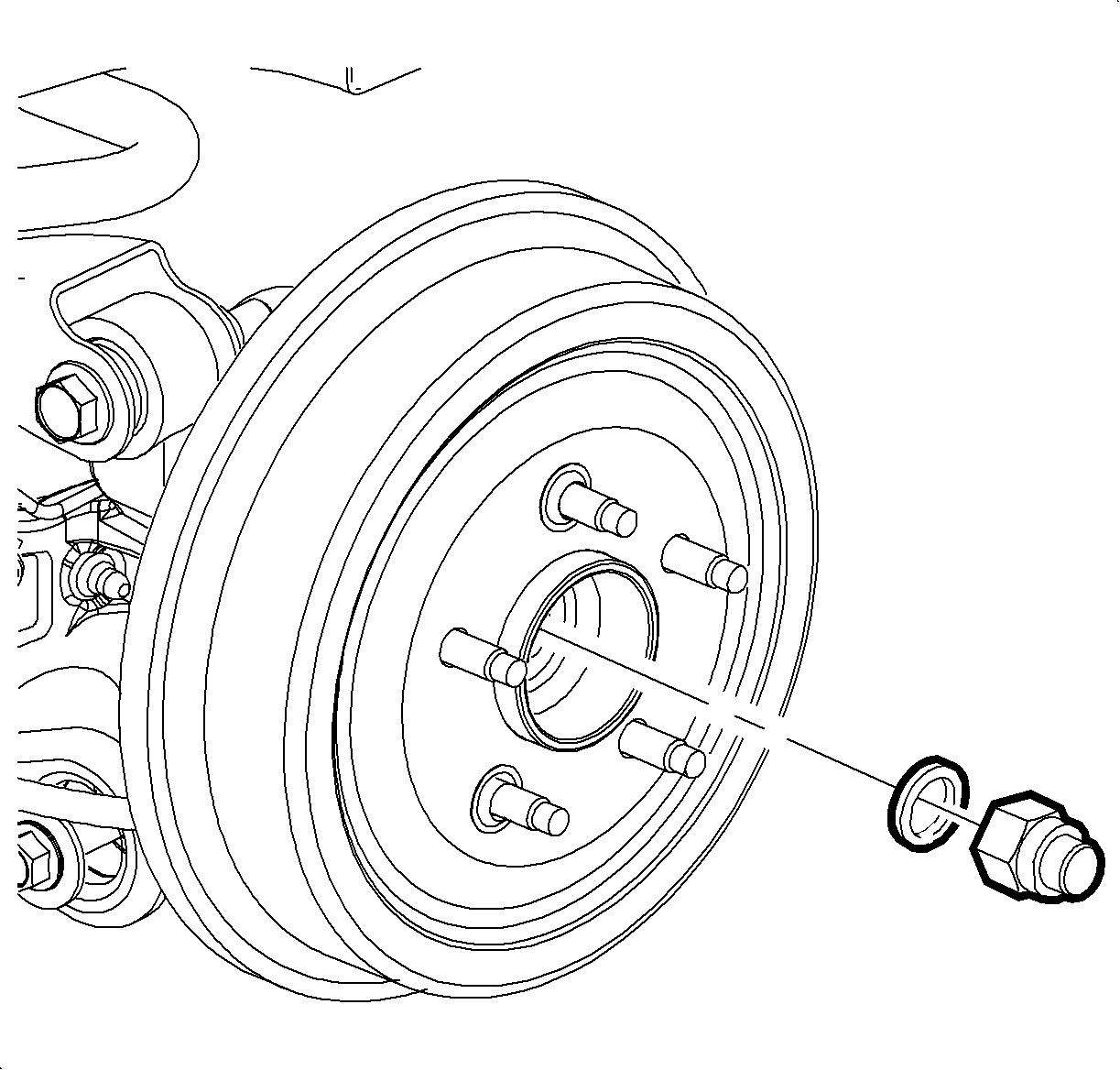
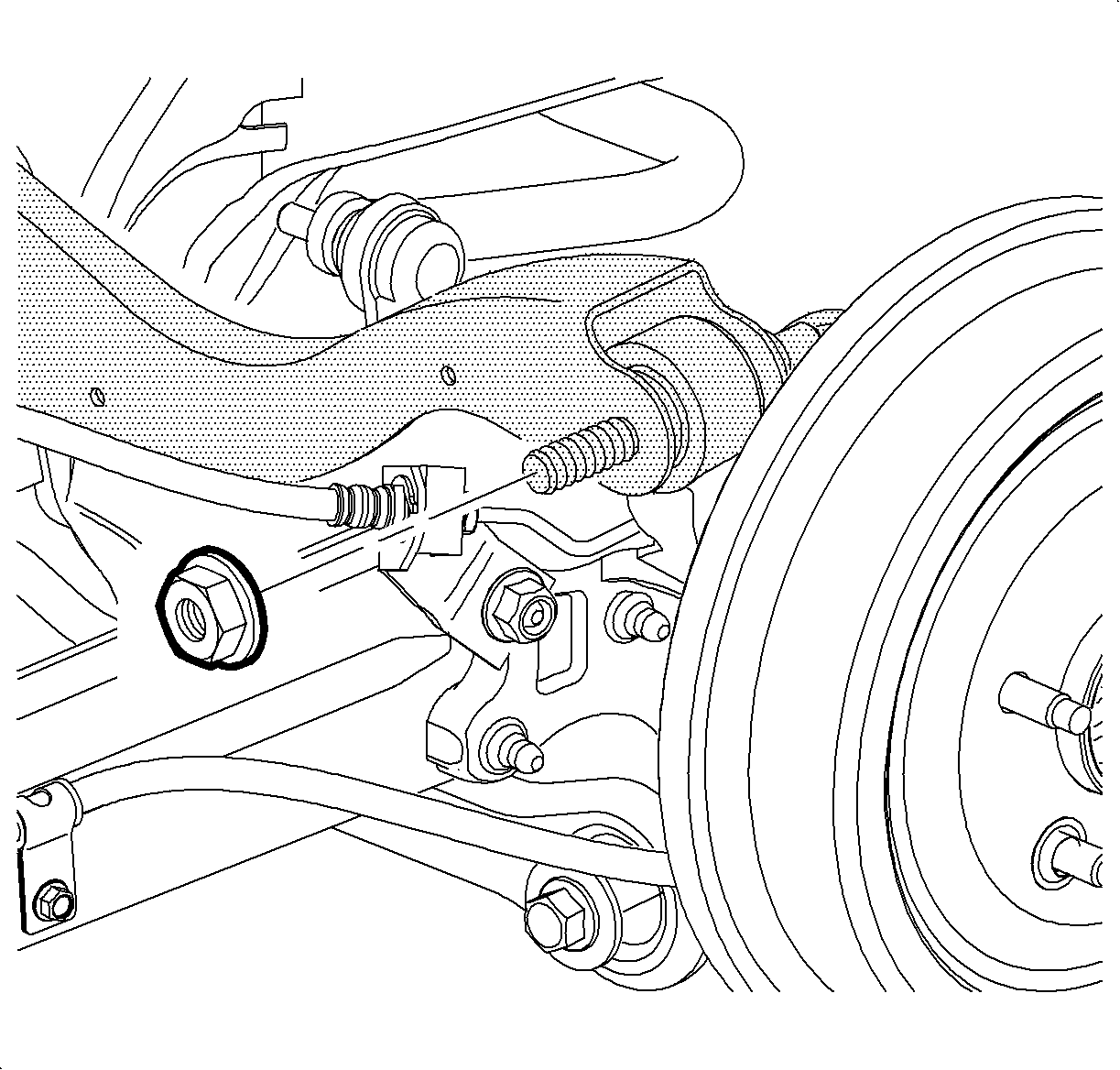
- Remove and discard the wheel drive shaft spindle nut.
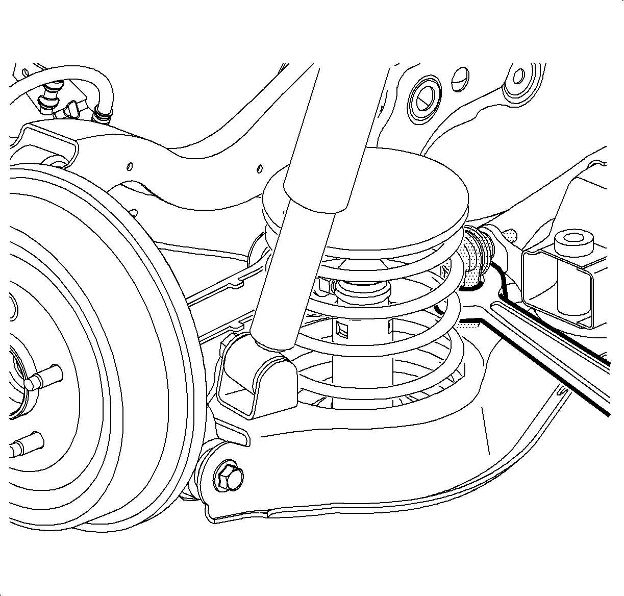
- While holding the stabilizer link with a wrench, remove the stabilizer link-to-lower control arm nut.
- Disconnect the link from the control arm.
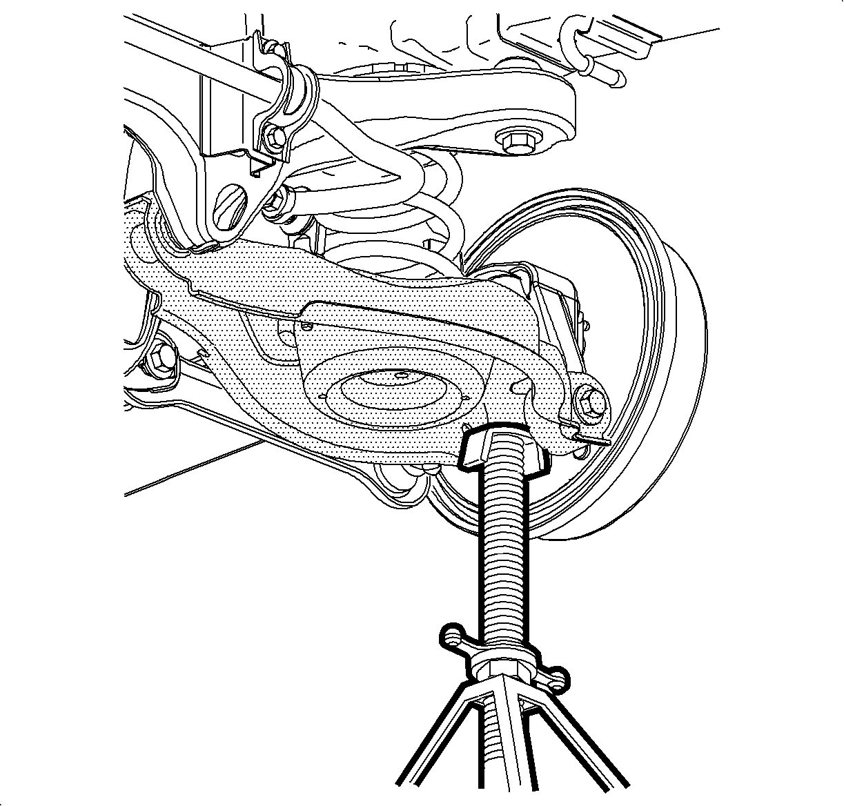
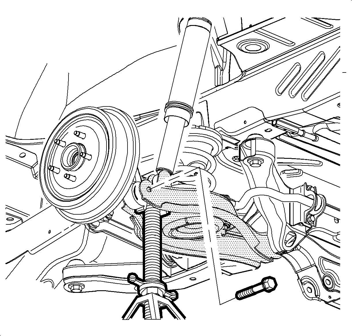
- Place a stand under the lower control arm and support the control arm.
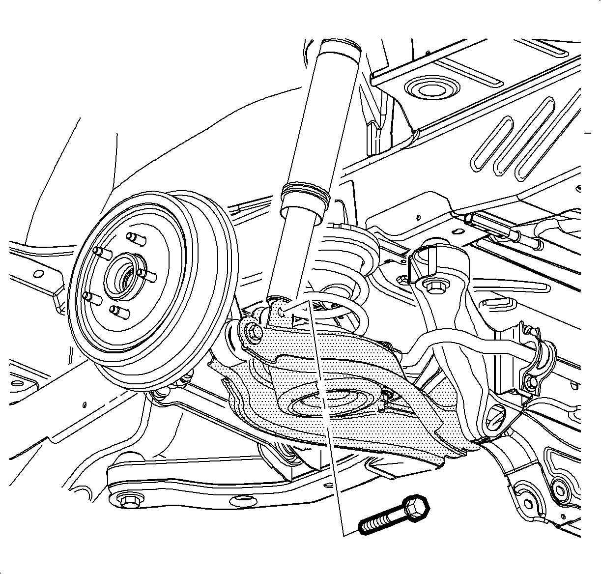
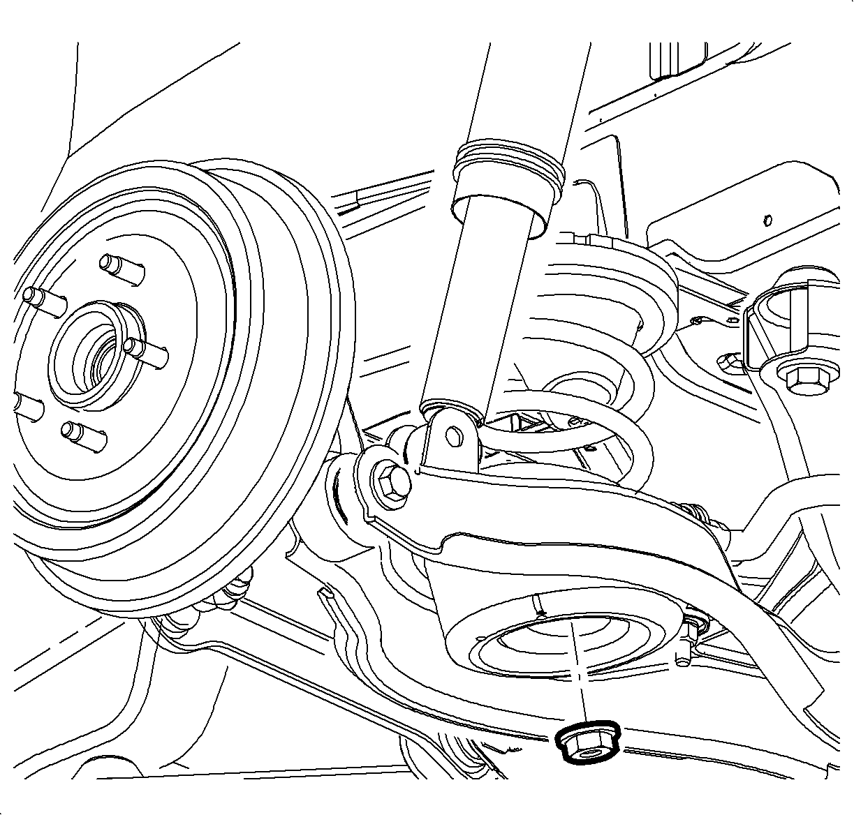
- Remove the lower shock absorber mounting bolt and nut.
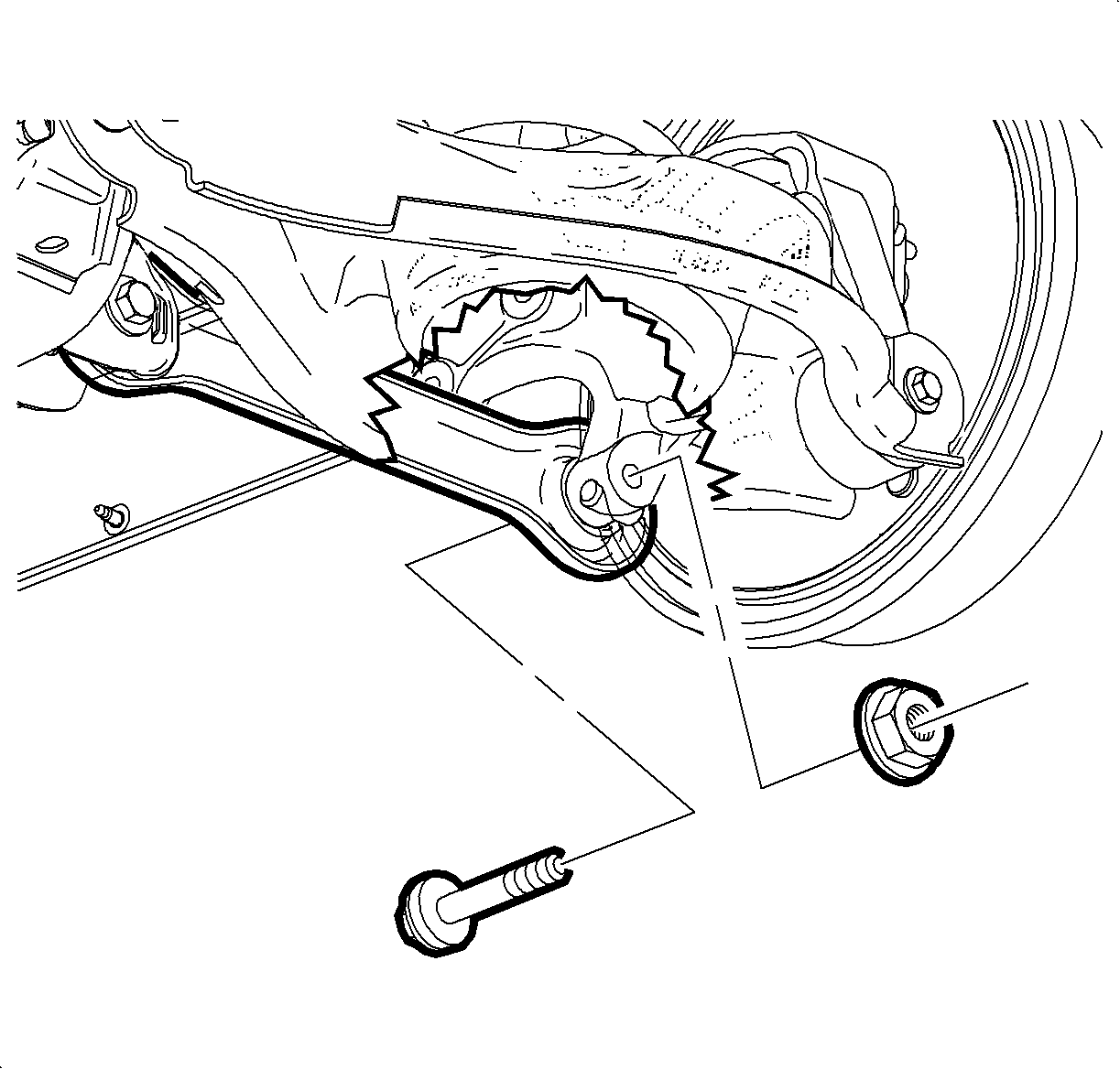
- Remove the toe link nut, bolt, and washer.
- Loosen, but do not remove, the lower suspension jounce bumper nut.
- Remove the lower control arm-to-suspension knuckle bolt and nut.
- Slowly lower support stand until coil spring tension is relieved and remove coil spring.
- Loosen, but do not remove, the upper control arm-to-suspension knuckle nut.
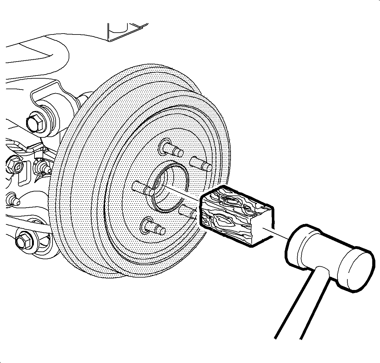
- Place a block of wood against the wheel drive shaft spindle and tap with a hammer to release the spindle from the wheel hub and bearing assembly.
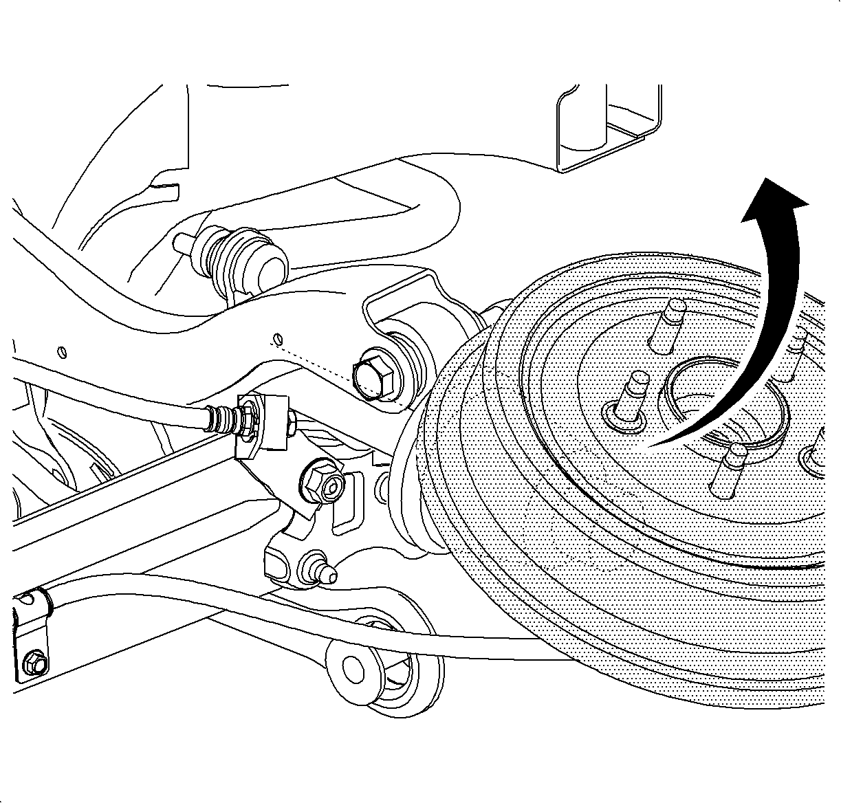
- Rotate the suspension knuckle upward and secure with heavy mechanics wire, or equivalent.
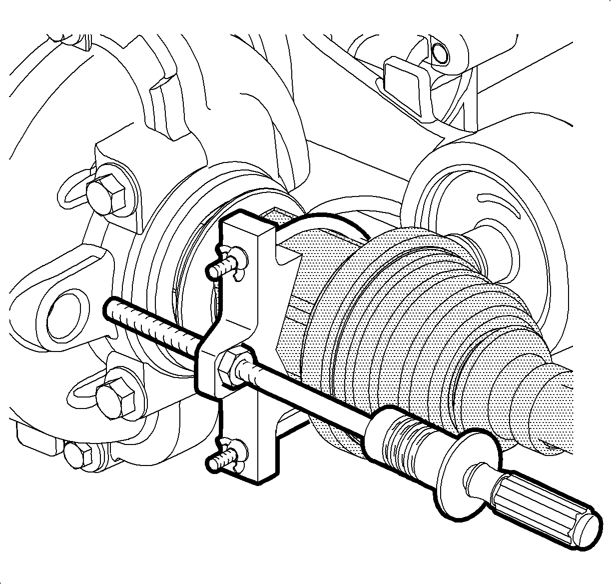
- Assemble the J 45341 and the J-2619-A to the wheel drive shaft inner tripot joint.
- Disengage the tripot joint from the rear drive module (RDM).
- Remove the wheel drive shaft from the vehicle.
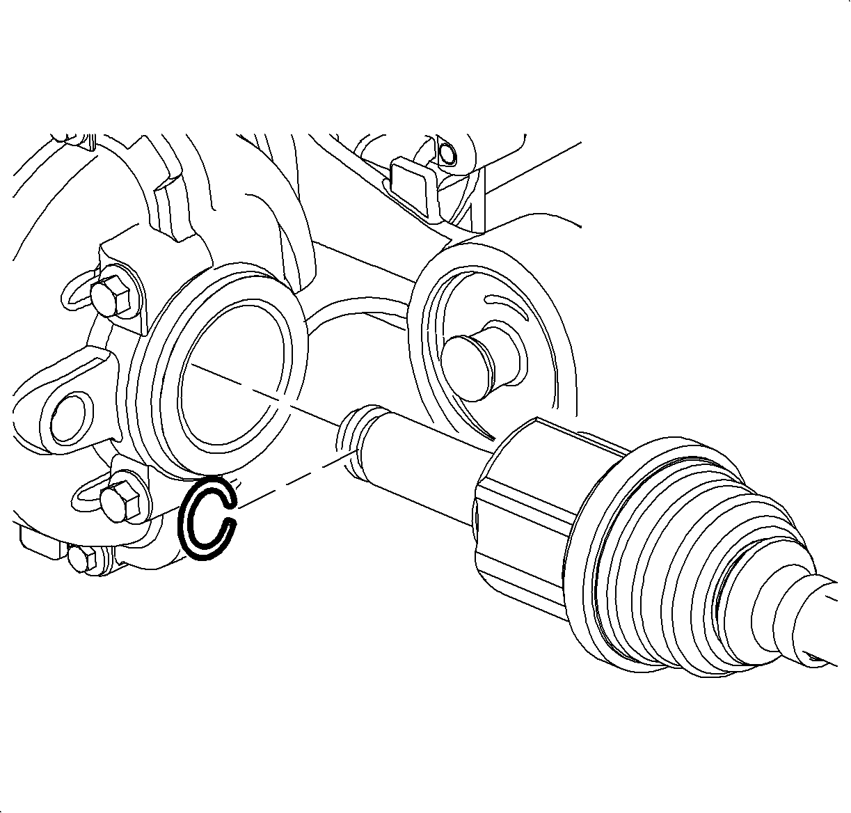
- Remove and discard the wheel drive shaft retaining ring.
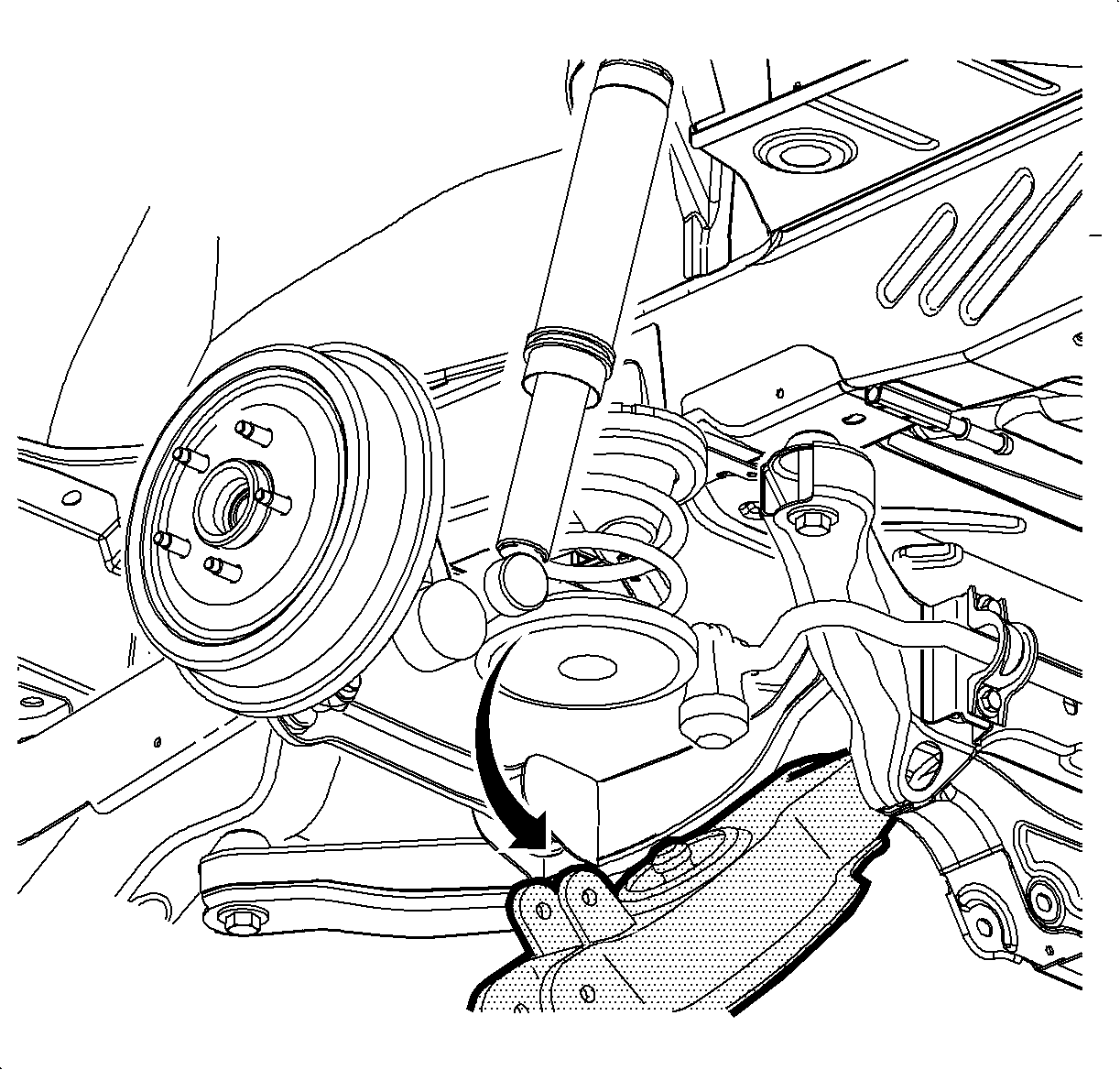
Important: Relieve spring tension slowly in order to avoid sudden release of the coil spring.
Important: Support the wheel drive shaft while it is disengaged from the wheel hub and bearing assembly in order to avoid damaging the wheel drive shaft seals.
Installation Procedure
- Install a new wheel drive shaft retaining ring to the inner tripot joint.
- Install the J 44394 to the wheel drive shaft oil seal.
- Align the splines of the inner tripot joint to the output shaft of the RDM.
- Install the wheel drive shaft to the output shaft:
- Rotate the suspension knuckle downward while simultaneously guiding the constant velocity (CV) joint spindle to the wheel hub and bearing assembly of the suspension knuckle.
- Hand install a new wheel drive shaft spindle nut.
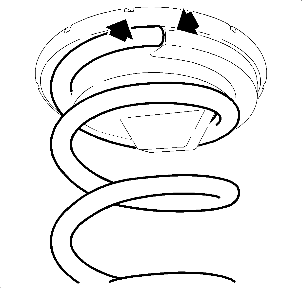
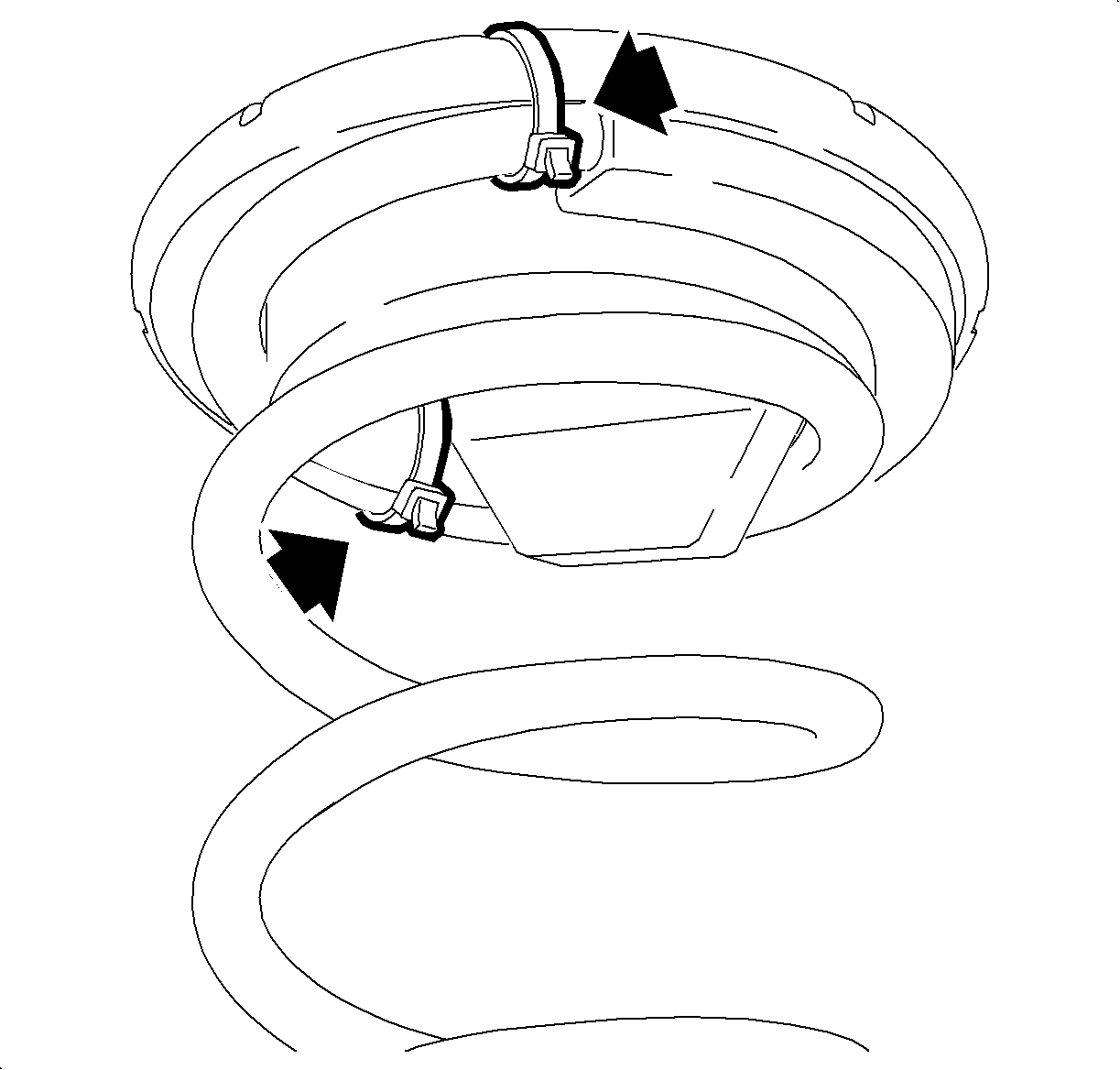
- Position the insulators to the coil spring and align the ends of the coil spring with the abutments of the insulators.
- Secure each of the insulators to the coil spring using 2 plastic tie straps positioned 180 degrees apart and through the reliefs molded into the insulators.
- Cut off any excess length of the tie straps.
- Position the coil spring assembly to the lower control arm.
- Position a support stand under the lower control arm.
- Carefully raise the lower control arm while simultaneously guiding the coil spring assembly into the rear suspension cradle.
- Position the suspension knuckle to the lower control arm.
- Install the lower control arm-to-suspension knuckle bolt and nut.
- Tighten the upper control arm-to-suspension knuckle bolt and nut.
- Install the lower shock absorber mounting bolt and nut.
- Slowly lower and remove the support stand.
- Tighten the lower jounce bumper nut.
- Position the rear toe link to the suspension knuckle.
- Install the washer, bolt, and nut to the suspension knuckle and the toe link assembly.
- Position the stabilizer bar link to the lower control arm.
- Install the nut to the stabilizer bar link.
- While holding the stabilizer bar link stationary with a wrench, tighten the nut.
- Tighten the wheel drive shaft spindle nut.
- Install the tire and wheel assembly. Refer to Tire and Wheel Removal and Installation .
- Lower the vehicle.

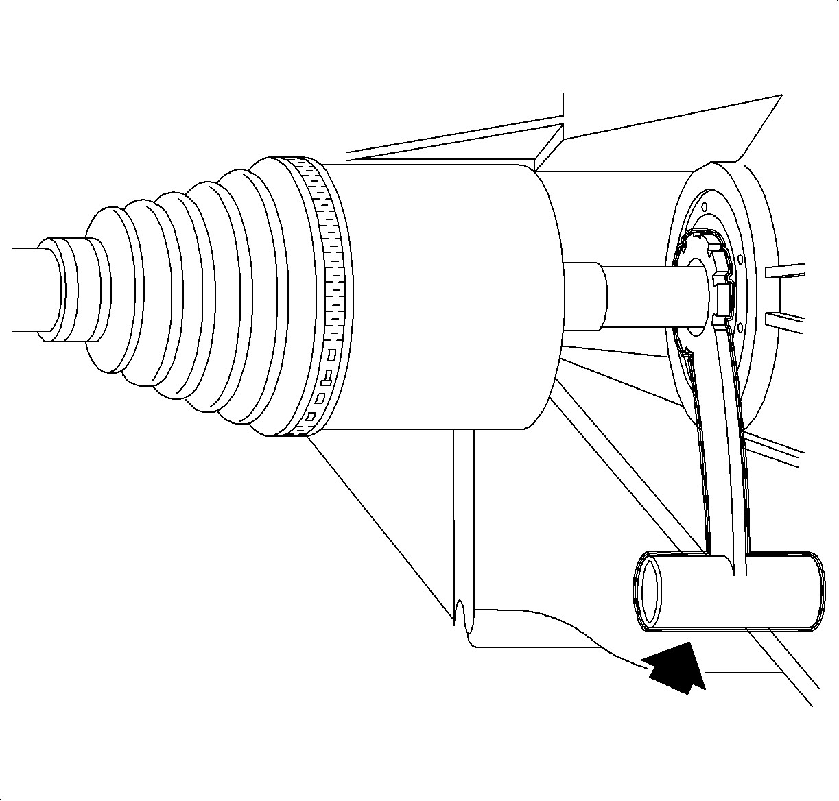
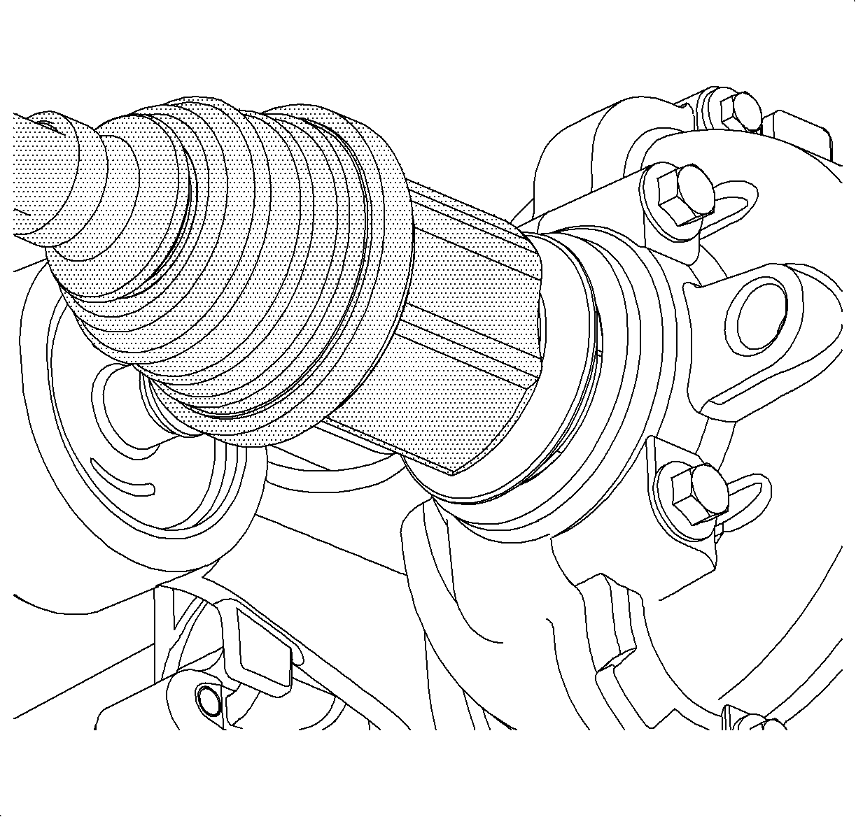
| • | Guide the wheel drive shaft tripot joint squarely onto the output shaft. |
| • | After the splined end of the wheel drive shaft passes the oil seal, remove the J 44394 from the oil seal. |
| • | Firmly engage the wheel drive shaft to the output shaft. |
| • | Ensure that the tripot joint is fully seated on the output shaft by grasping the tripot joint and attempting to pull free of the output shaft. |
| • | Ensure that the tripot slinger does not become damaged. |



Notice: Refer to Fastener Notice in the Preface section.
Important: Ensure that the hex head of the suspension knuckle bolt faces the rear of the vehicle.
Tighten
Tighten the bolt and nut to 160 N·m (118 lb ft).

Tighten
Tighten the bolt and nut to 135 N·m (100 lb ft).

Tighten
Tighten the bolt and nut to 105 N·m (77 lb ft).
Tighten
Tighten the nut to 63 N·m (46 lb ft).

Tighten
Tighten the bolt and nut to 110 N·m (81 lb ft).

Tighten
Tighten the nut to 15 N·m (11 lb ft).
Tighten
Using the
J 45059
, tighten the nut to 86 N·m (63 lb ft) plus 36 degrees.
