GM Service Manual Online
For 1990-2009 cars only
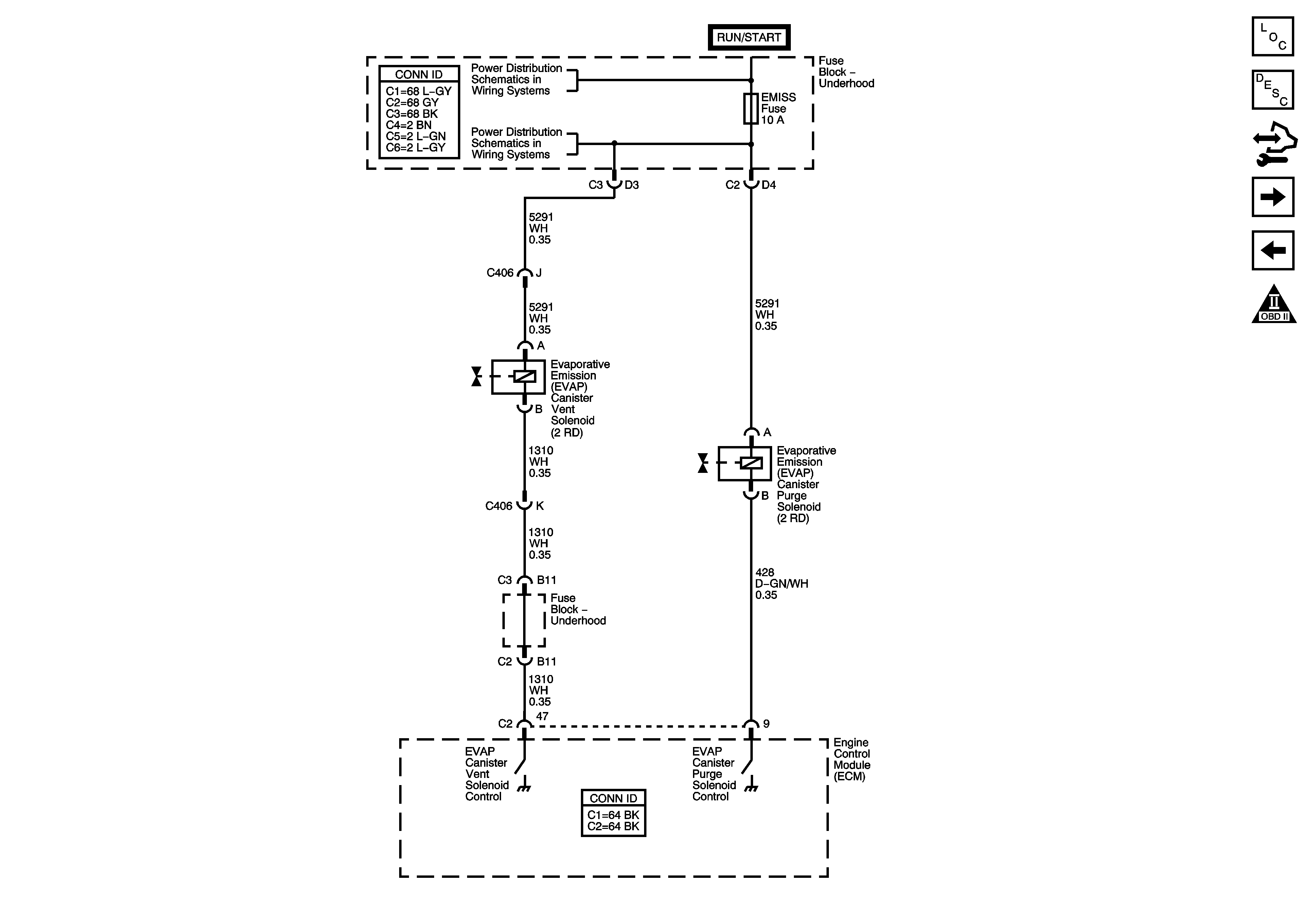
Figure 1:

Power, Ground, Communication and the MIL

Object Number: 1583961  Size: FS
Master Electrical Component List
Engine Control Module Description
Control Module References
5-Volt and Low References
Engine Controls Schematic Icons
IGN Fuse and the Ignition Switch Circuits
B+ Bussing and the EPS Fuse
IGN/INJ Fuse, EMISS Fuse and the ETC Fuse - L61
BACKUP Fuse, PWR TRAIN Fuse, 10A ABS Fuse and the INJECTORS (L66) Fuse
IGN1 Fuse, BCM(IGN) Fuse, AIR BAG Fuse, EPS Fuse and the CRUISE Fuse
Indicators and Serial Data
G107 and G109 - L66
L66
DLC Schematic (M/T)
Figure 2:

5-Volt and Low References


Object Number: 1583962  Size: FS
Master Electrical Component List
Engine Control Module Description
Control Module References
Engine Data Sensors - Pressure and Temperature Sensors
Power, Ground, Communication and the MIL
Engine Controls Schematic Icons
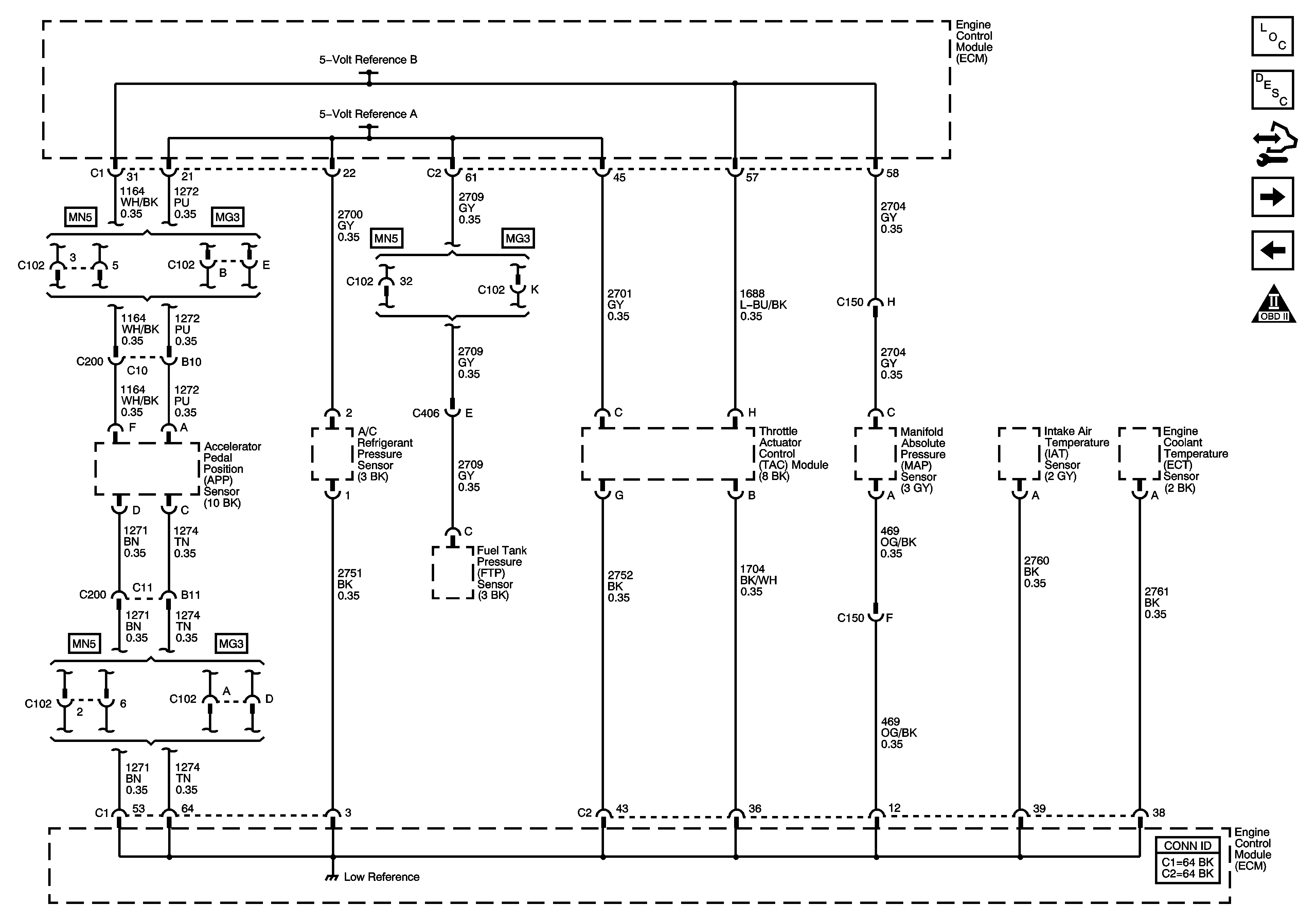
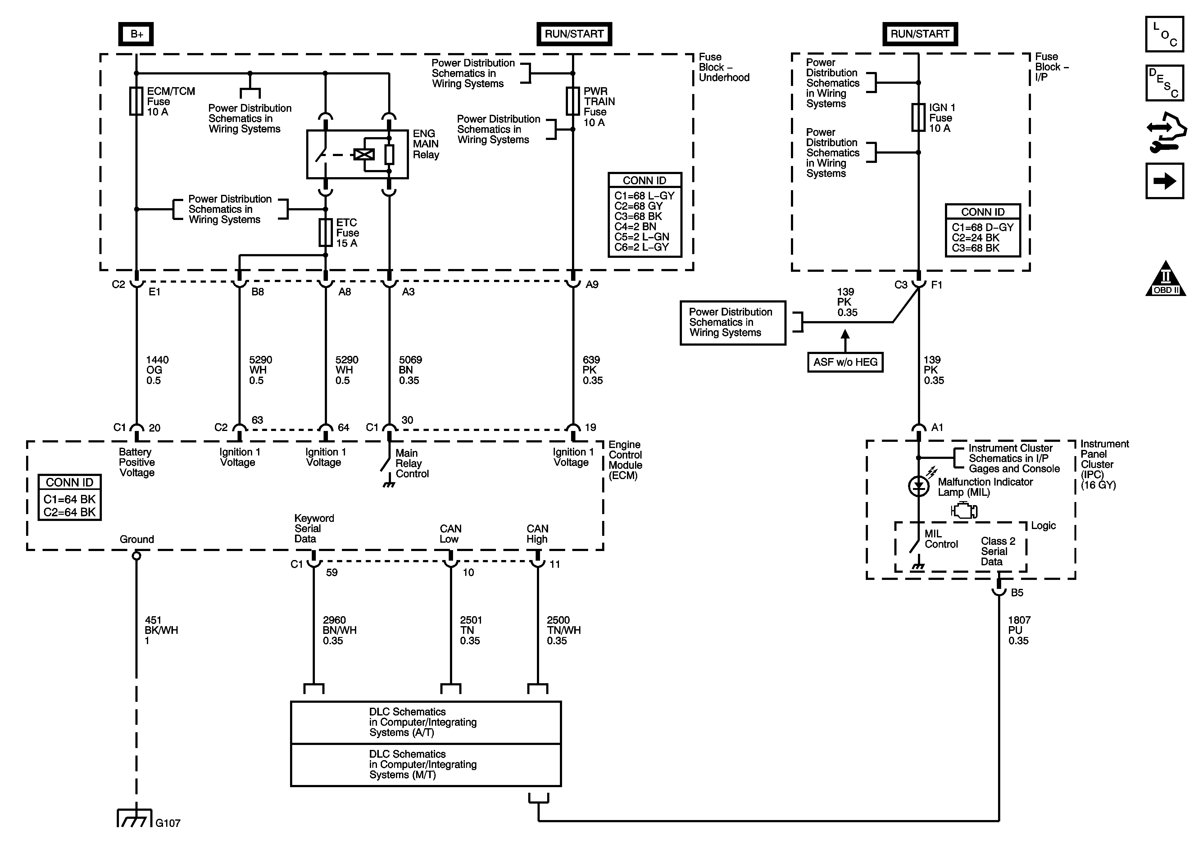
Figure 3:

Engine Data Sensors - Pressure and Temperature Signals

Object Number: 1583963  Size: FS
Master Electrical Component List
Engine Control Module Description
Control Module References
TAC and APP Sensor Signals
5-Volt and Low References
Engine Controls Schematic Icons
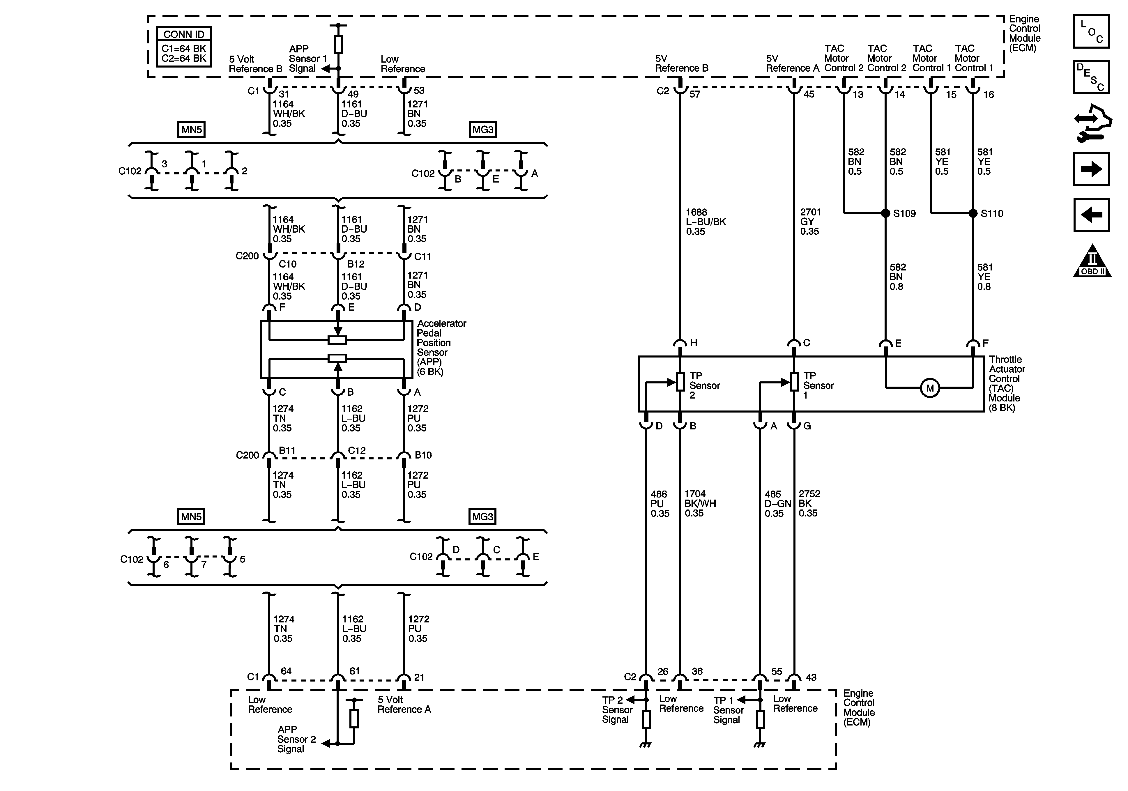
Figure 4:

TAC and APP Sensor Signals


Object Number: 1615352  Size: FS
Master Electrical Component List
Engine Control Module Description
Control Module References
Engine Data Sensors - Oxygen Sensors
Engine Data Sensors - Pressure and Temperature Sensors
Engine Controls Schematic Icons
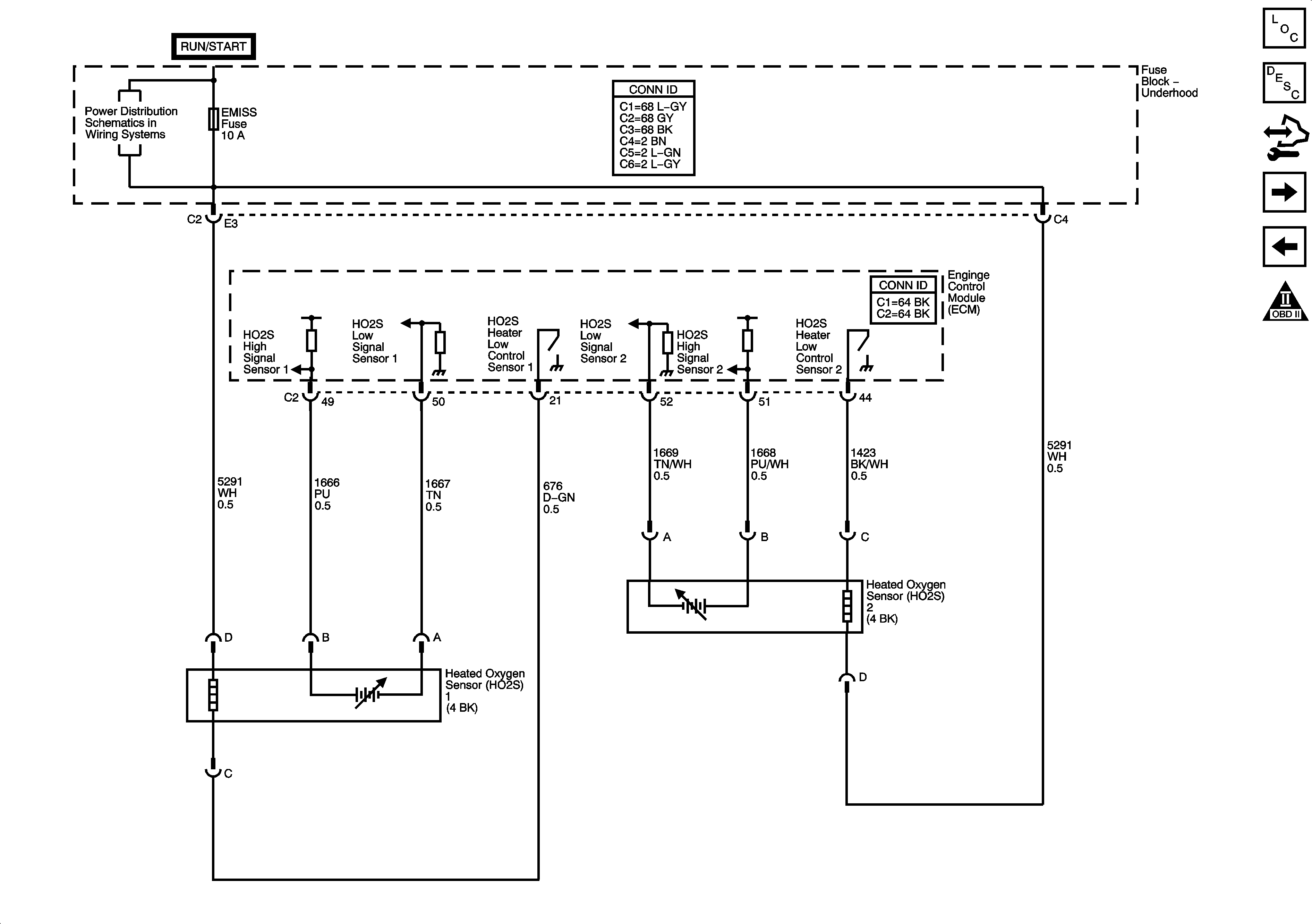
Figure 5:

Engine Data Sensors - Oxygen Sensors


Object Number: 1583964  Size: FS
Master Electrical Component List
Engine Control Module Description
Control Module References
Ignition Controls
TAC and APP Sensor Signals
Engine Controls Schematic Icons
EMISS Fuse and the ETC Fuse - L66
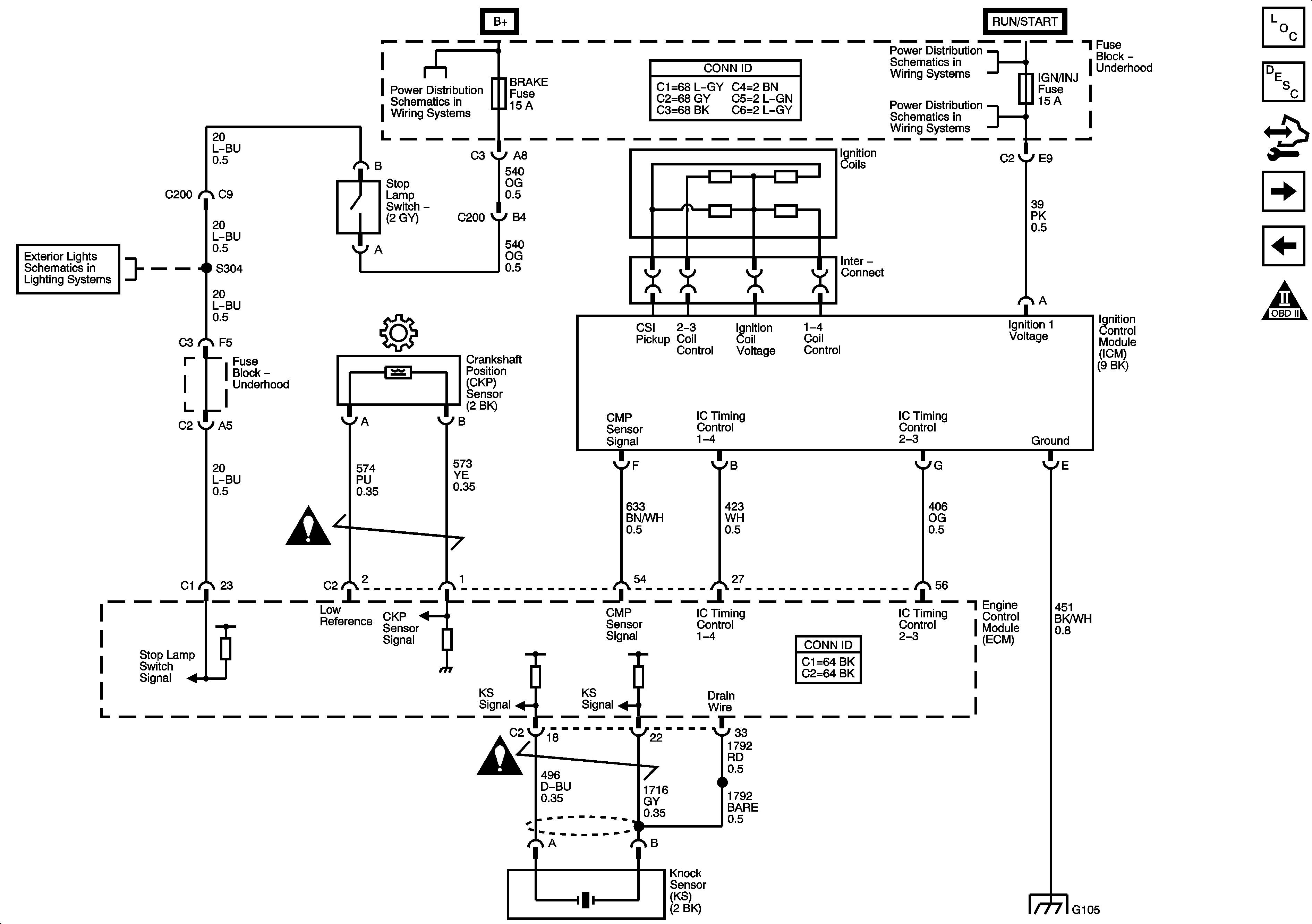
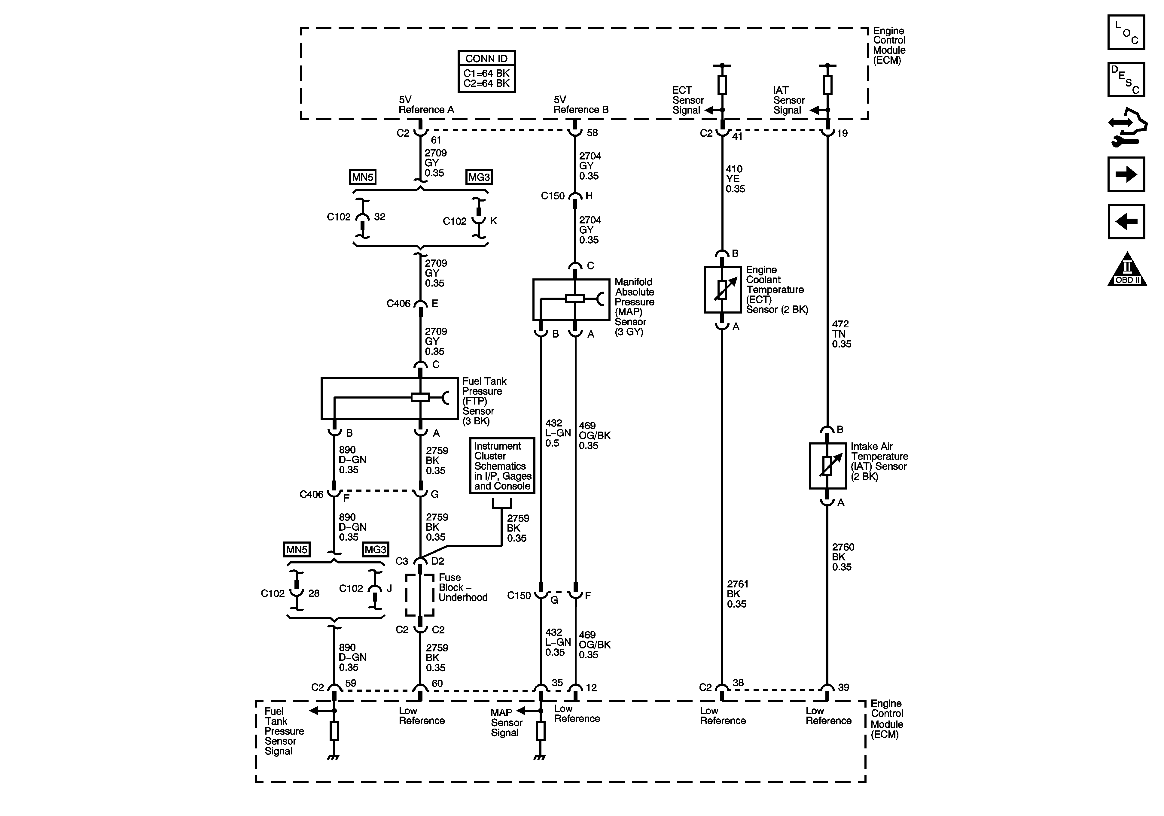
Figure 6:

Ignition Controls


Object Number: 1583965  Size: FS
Master Electrical Component List
Engine Control Module Description
Control Module References
Fuel Controls - Fuel Pump and Injectors
Engine Data Sensors - Oxygen Sensors
Engine Controls Schematic Icons
B+ Bussing and the EPS Fuse
IGN Fuse and the Ignition Switch Circuits
IGN/INJ Fuse, EMISS Fuse and the ETC Fuse - L61
Stop Lamps
G103, G105 and G207
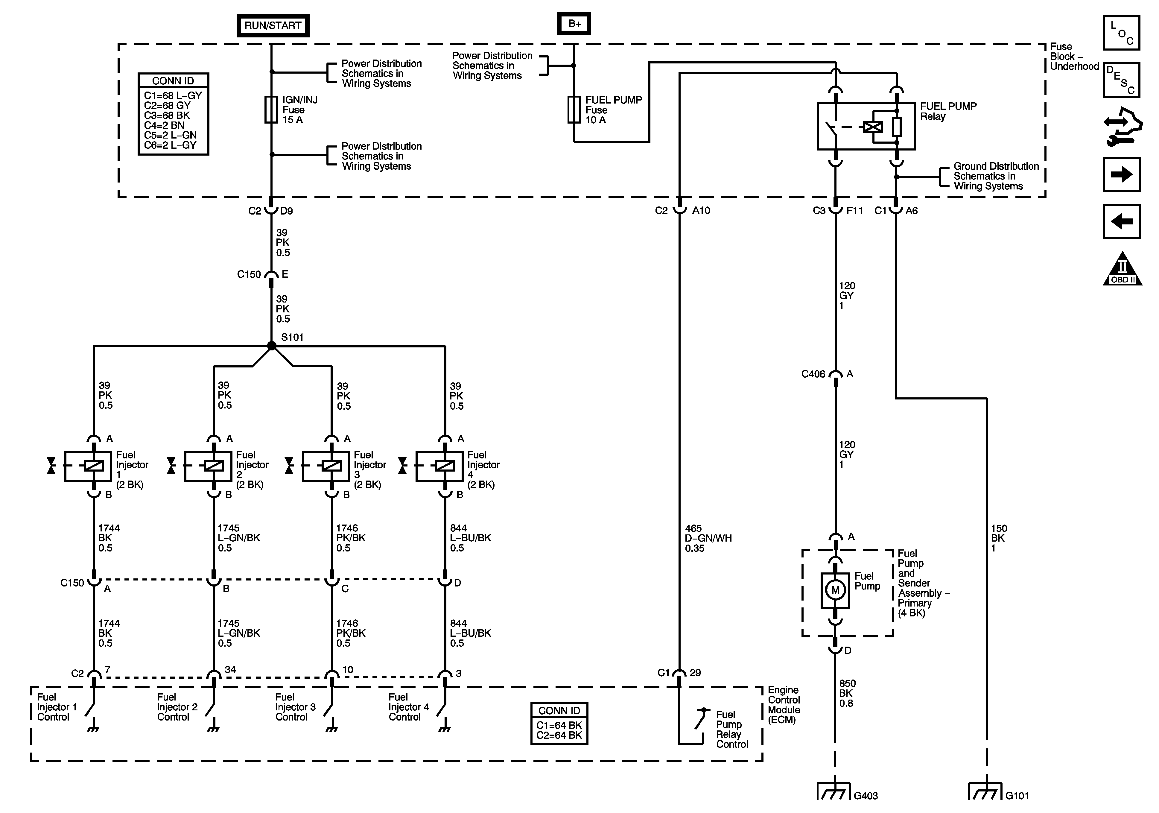
Figure 7:

Fuel Controls - Fuel Pump and Injectors


Object Number: 1583966  Size: FS
Master Electrical Component List
Fuel System Description
Control Module References
Fuel Controls - EVAP Controls
Ignition Controls
Engine Controls Schematic Icons
IGN Fuse and the Ignition Switch Circuits
B+ Bussing and the EPS Fuse
IGN/INJ Fuse, EMISS Fuse and the ETC Fuse - L61
G401 and G403
G101
Figure 8:

Fuel Controls - EVAP Controls


Object Number: 1583967  Size: FS
Master Electrical Component List
Evaporative Emission Control System Description
Control Module References
Controlled/Monitored Subsystem References
Fuel Controls - Fuel Pump and Injectors
Engine Controls Schematic Icons
B+ Bussing and the EPS Fuse
EMISS Fuse and the ETC Fuse - L66
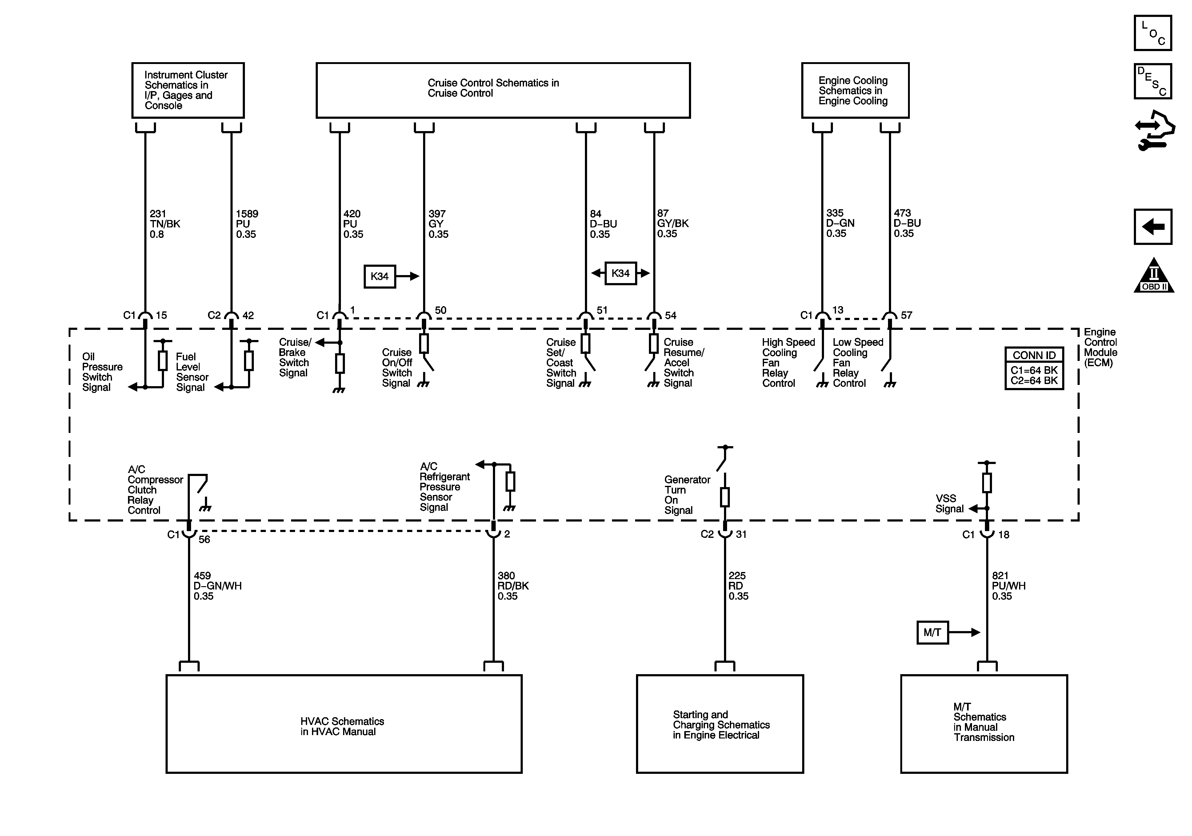
Figure 9:

Controlled/Monitored Subsystem References


Object Number: 1583968  Size: FS
Master Electrical Component List
Engine Control Module Description
Control Module References
Fuel Controls - EVAP Controls
Engine Controls Schematic Icons
Indicators and Serial Data
Cruise Control Schematic
Engine Cooling Schematic (L61)
Compressor and Pressure Sensor Signals
Charging and Indicators
Manual Transmission Schematic