GM Service Manual Online
For 1990-2009 cars only

Purpose

The throttle actuator control (TAC) system delivers improved throttle response and greater reliability and eliminates the need for mechanical cable. The TAC system performs the following functions:

    • Accelerator pedal position sensing
    • Throttle positioning to meet driver and engine demands
    • Throttle position sensing
    • Internal diagnostics
    • Cruise control functions

The TAC system includes the following components:

    • The accelerator pedal position (APP) sensors
    • The throttle body assembly
    • The powertrain control module (PCM)

Accelerator Pedal Position (APP) Sensor


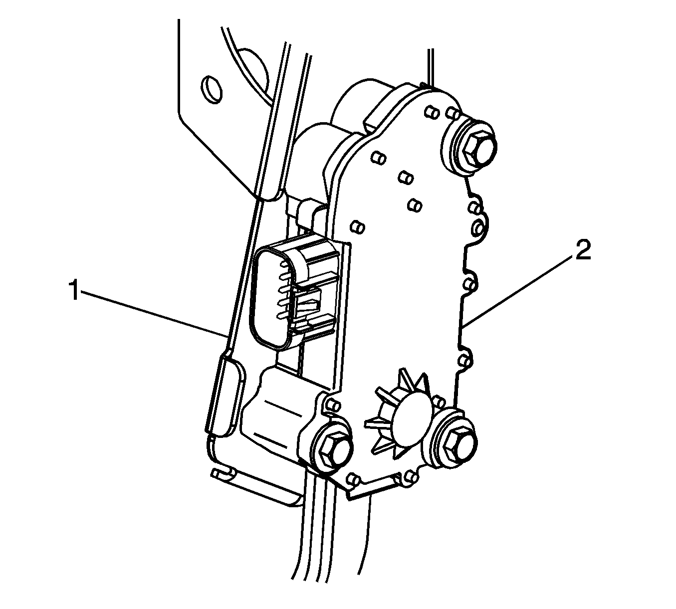
Object Number: 1255638  Size: SH

The accelerator pedal position (APP) sensor assembly (2) is fastened to the accelerator pedal assembly and attached to the brake pedal bracket (1). The APP sensor assembly contains two APP sensors that are operated by the accelerator pedal movement. The APP sensors 1 and 2 are potentiometer type sensors each with 3 circuits:

    • A 5-volt reference circuit
    • A low reference circuit
    • A signal circuit

The APP sensors are used to determine the pedal angle. The powertrain control module (PCM) provides each APP sensor a 5-volt reference circuit and a low reference circuit. The APP sensors provide the PCM with signal voltage proportional to the pedal movement. APP sensor 1 signal voltage is low at the rest position and increases to near the 5-volt reference as the pedal is applied. APP sensor 2 signal is low at rest and also increases as the accelerator pedal is applied. APP sensor 2 increases at a different rate to approximately half the reference voltage. The APP sensor 1 is responsible for providing the actual pedal position to the PCM. The PCM then sends a throttle position target value to the TAC control module. APP sensor 2 provides a backup value to the APP sensor 1.
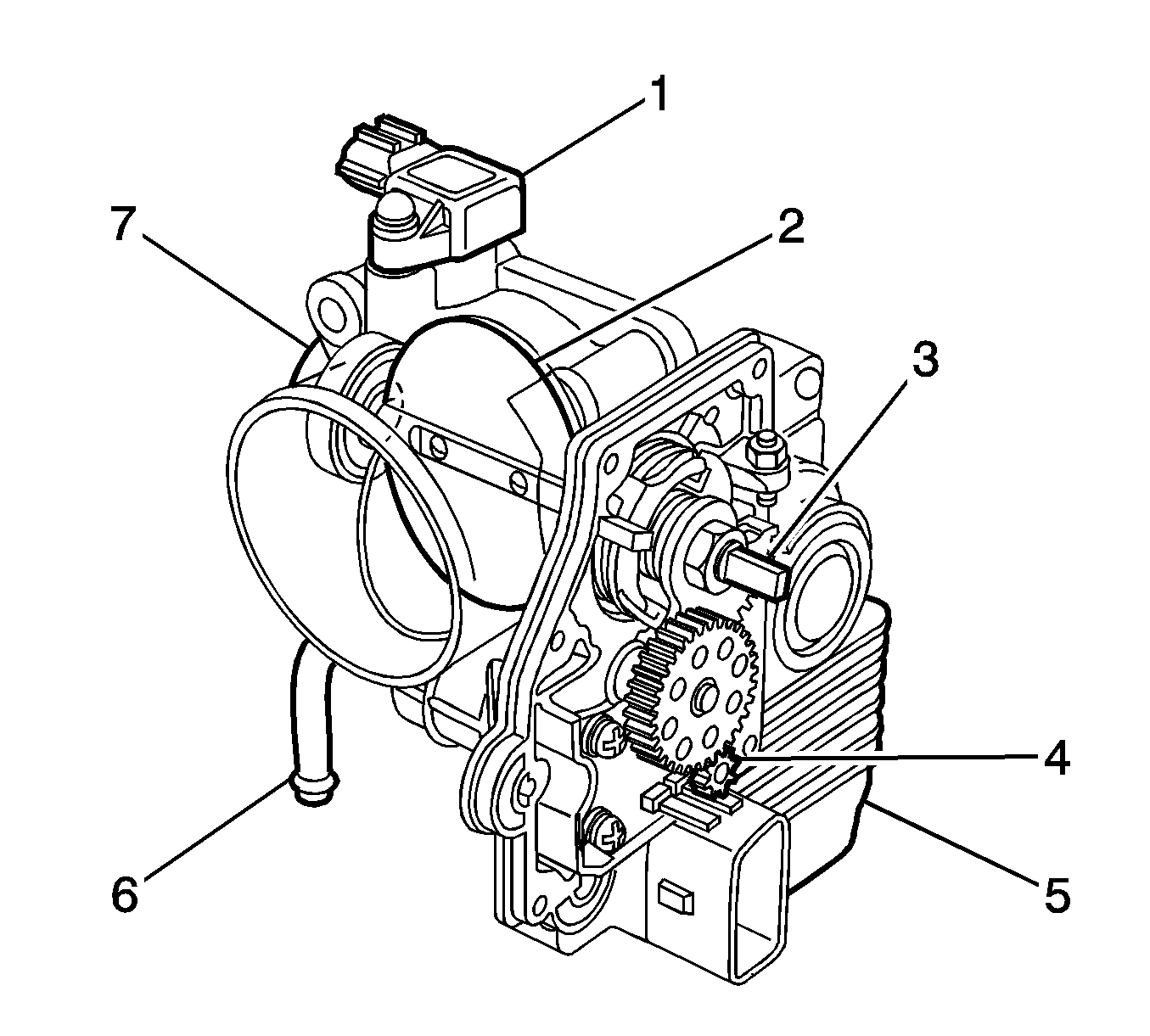
Throttle Body Assembly


Object Number: 1233239  Size: SH
(1)Manifold Absolute Pressure (MAP) Sensor
(2)Throttle Valve, Plate
(3)Throttle Shaft
(4)Throttle Control Motor Drive Gear
(5)Throttle Actuator Control (TAC) Module Cover
(6)Engine Coolant Pipe
(7)Throttle Body Housing

The throttle body functions similar to a conventional throttle body with the following exceptions:

    • An electric motor opens and closes the throttle valve.
    • The TAC module is an integral part of the throttle body assembly.
    • The throttle valve is spring loaded and the default position is slightly open.
    • There are 2 individual throttle position (TP) sensors integral to the TAC module cover.

The TP sensors are used to determine the throttle plate angle. The TP sensors provide the TAC module with a signal voltage proportional to throttle plate movement. Both TP sensor signal voltages are low at closed throttle and increase as the throttle opens. TP sensor 1 determines the actual throttle valve position. TP sensor 2 provides a backup value for TP sensor 1.

Throttle Actuator Control (TAC) Module

The throttle actuator control (TAC) module is the control center for the TAC system. The TAC module uses Read Only Memory (ROM) and Random Access Memory (RAM) along with an analog/digital (A/D) converter to control engine speed. The TAC module is self-diagnosing and communicates to the powertrain control module (PCM) with a dedicated serial data line. The TAC module receives accelerator pedal position (APP) sensor information from the PCM and provides diagnostic information to the PCM.

The APP sensor 1 enables the PCM to provide a target value to the TAC module in response to accelerator pedal movement. The TAC module achieves the correct throttle position by commanding the throttle control motor to position the throttle valve at the target value. The TAC module then compares the throttle position (TP) sensor 1 value to the target value. If necessary, the throttle control motor is moved slightly to obtain the exact desired position. The TAC module is not serviced separately and must be replaced with the throttle body assembly.

Powertrain Control Module

The powertrain control module (PCM) determines the drivers intent and then calculates the appropriate throttle response. This information is sent to the throttle actuator control (TAC) module through a dedicated serial data line.

Modes of Operation

Normal Mode

During the operation of the throttle actuator control (TAC) system, several modes or functions are considered normal. The following modes may be entered during normal operation:

    • Learned idle mode--When ever the powertrain control module (PCM) recognizes the learned idle throttle position (TP) value, the engine operates in the learned idle mode. In the learned idle mode, the PCM uses stored engine performance settings in order to provide the best quality idle for all idle speed situations.
    • Learned idle TP values--The TAC module relies on a stored TP sensor value for optimum idle speed operation. After PCM replacement or PCM reset, a new TP sensor value is learned and stored in the PCM memory. Refer to the Idle Learn Procedure below.
    • Cold engine start mode--The throttle valve has a default start position that ensures improved cold engine starting and cold engine operation. In the cold engine start mode the TAC module commands the throttle control motor to the default position. In case of a TAC system malfunction, the default position spring opens the throttle valve to the default position.

Reduced Engine Power Mode

When the PCM detects a condition with the TAC system, the PCM may enter a reduced engine power mode. Reduced engine power may cause one or more of the following conditions:

    • Acceleration limiting--The PCM will continue to use the accelerator pedal for throttle control; however, the vehicle acceleration is limited.
    • Limited throttle mode--The PCM will continue to use the accelerator pedal for throttle control; however, the maximum throttle opening is limited.
    • Throttle default mode--The PCM will turn off the throttle actuator motor and the throttle will return to the spring loaded default position.
    • Forced idle mode--The PCM will perform the following actions:
       - Limit engine speed to idle by positioning the throttle position, or by controlling the fuel and spark if the throttle is turned OFF.
       - Ignore the accelerator pedal input.
    • Engine shutdown mode--The PCM will disable fuel and de-energize the throttle actuator.

Idle Learn Procedure

When performing certain maintenance procedures, or when performing certain vehicle repairs, the idle learn procedure must be initiated. On a new or reset powertrain control module (PCM), the learned idle position is determined by the throttle position (TP) sensor value that is recognized when the ignition is first turned ON. The value is then retained in memory. A new value is automatically calculated by the PCM whenever there no idle learn value stored in memory. The idle learn procedure begins the learning of a new idle position when there is no old idle position value in the PCM memory. Performing the idle learn procedure is required for the following conditions:

    • The throttle body assembly is replaced
    • The throttle valve is cleaned--Deposits can build up in the throttle body requiring periodic cleaning of the throttle valve and throttle bore area. Refer to Throttle Body Inspection and Cleaning .
    • The Clear DTCs function has been performed
    • The PCM has been programmed.
    • The PCM is replaced

If the PCM was replaced, proceed directly to the idle learn procedure. For the other actions above, the old learned idle position will be erased when the scan tool clear DTCs function is performed. Once the old learned idle position is erased, the idle learn procedure must be performed. Refer to Idle Learn .

TP Sensor Learned Value

On a new powertrain control module (PCM), the throttle position (TP) learned value is determined by the TP sensor value that is recognized when the ignition is first turned ON. The value is then retained in memory. This value is used as a baseline for a correlation between the TP input and the volume of intake air flow at idle. After many operating hours, deposits collect on the throttle plate and the bore of the throttle body. These deposits cause a restriction in the air flow at idle and can reduce engine performance at idle. In order to maintain engine idle quality, the PCM commands the throttle plate open slightly, correcting for the decreased air flow. Whenever this occurs, a new relationship is created between the TP sensor input and the actual throttle plate position. This relationship is the TP learned value.

When the throttle body is replaced, or the carbon deposits are removed, the TP learned value must be reset. If the value is not reset, the engine operates using stored values that are incorrect, resulting in a poor idle or hard starting. Resetting the TP learned value is required for the following conditions:

    • The throttle body assembly is replaced
    • The throttle valve is cleaned--Deposits can build up in the throttle body requiring periodic cleaning of the throttle valve and throttle bore area. Refer to Throttle Body Inspection and Cleaning .
    • The PCM has been programmed.
    • The PCM memory has been lost--as could happen with a long term power loss.

The TP learned value can be reset using the scan tool. Refer to Scan Tool Output Controls .