GM Service Manual Online
For 1990-2009 cars only
Table 1: Fuel Trim Operation
Table 2: Closed Loop Fuel Control Operation

Fuel System Overview

The fuel system is a returnless on-demand design. The fuel pressure regulator is a part of the primary fuel tank module, eliminating the need for a return pipe from the engine. A returnless fuel system reduces the internal temperature of the fuel tank by not returning hot fuel from the engine to the fuel tank. Reducing the internal temperature of the fuel tank results in lower evaporative emissions.

An electric turbine style fuel pump attaches to the primary fuel tank module inside the fuel tank. The fuel pump supplies high pressure fuel through the fuel filter, past the fuel pressure regulator, and through the fuel feed pipe to the fuel injection system. The fuel pressure regulator has a T-joint that diverts the needed fuel to the fuel rail with the unused fuel dropping back into the reservoir of the primary fuel tank module. The primary fuel tank module contains a reverse flow check valve. The check valve and the fuel pressure regulator maintain fuel pressure in the fuel feed pipe and the fuel rail in order to prevent long cranking times.

The primary fuel tank module also contains a primary jet pump and a secondary jet pump. Fuel pump flow loss, caused by vapor expulsion in the pump inlet chamber, is diverted to the primary jet pump and the secondary jet pump through a restrictive orifice located on the pump cover. The primary jet pump fills the reservoir of the primary fuel tank module. The secondary jet pump creates a venturi action which causes the fuel to be drawn from the secondary side of the fuel tank, through the fuel transfer pipe, to the primary side of the fuel tank.

Fuel Tank


Object Number: 1335218  Size: SH

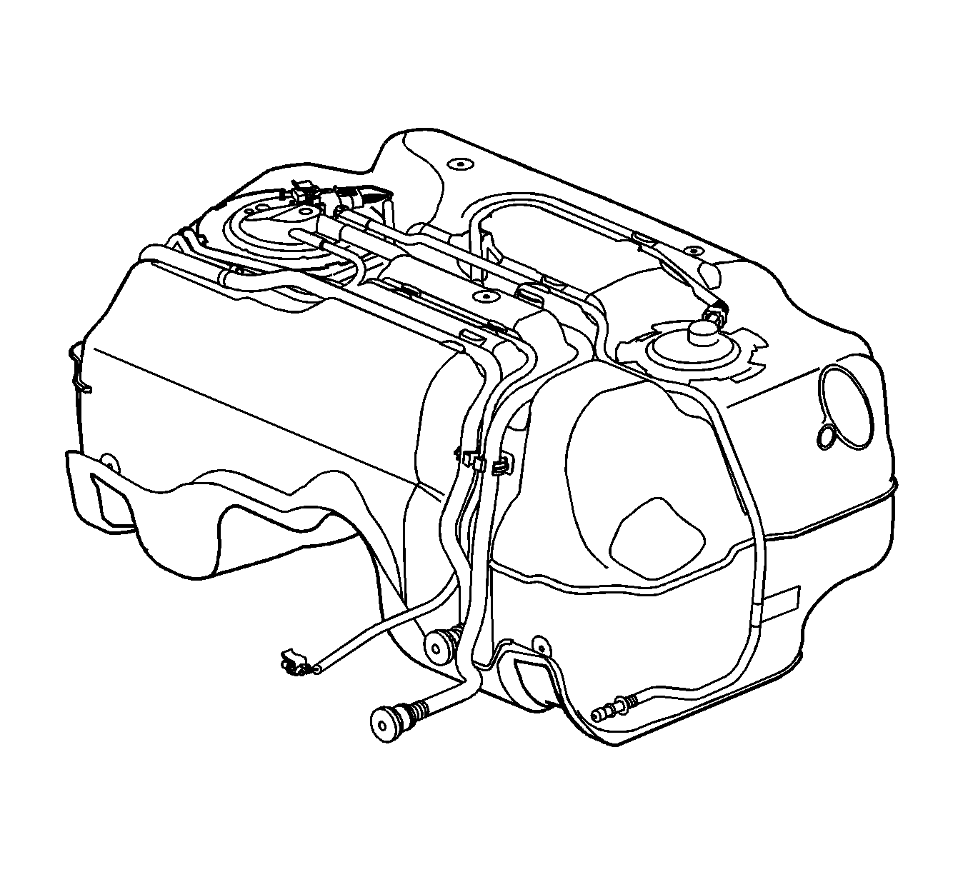
The fuel tank stores the fuel supply. The fuel tank is located in the rear of the vehicle. The fuel tank is held in place by 2 metal straps that attach to the under body of the vehicle. The fuel tank is molded from high-density polyethylene.

In order to provide space for a driveshaft though the center area of the tank, the fuel tank is a saddle configuration. Because of the saddle shape of the tank two fuel tank modules are required. The primary fuel tank module is located on the right side of the tank. The secondary fuel tank module is located on the left side of the tank.

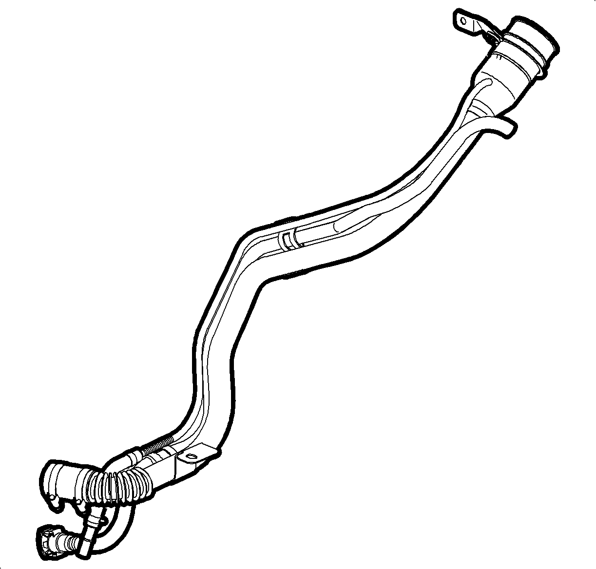
Fuel Fill Pipe


Object Number: 934056  Size: SH

The fuel fill pipe has a built-in restrictor in order to prevent refueling with leaded fuel.

Fuel Filler Cap

The fuel fill pipe has a tethered fuel filler cap. A torque-limiting device prevents the cap from being over-tightened. To install the cap, turn the cap clockwise until you hear audible clicks. This indicates that the cap is correctly torqued and fully seated. A fuel filler cap that is not fully seated may cause a malfunction in the emission system.

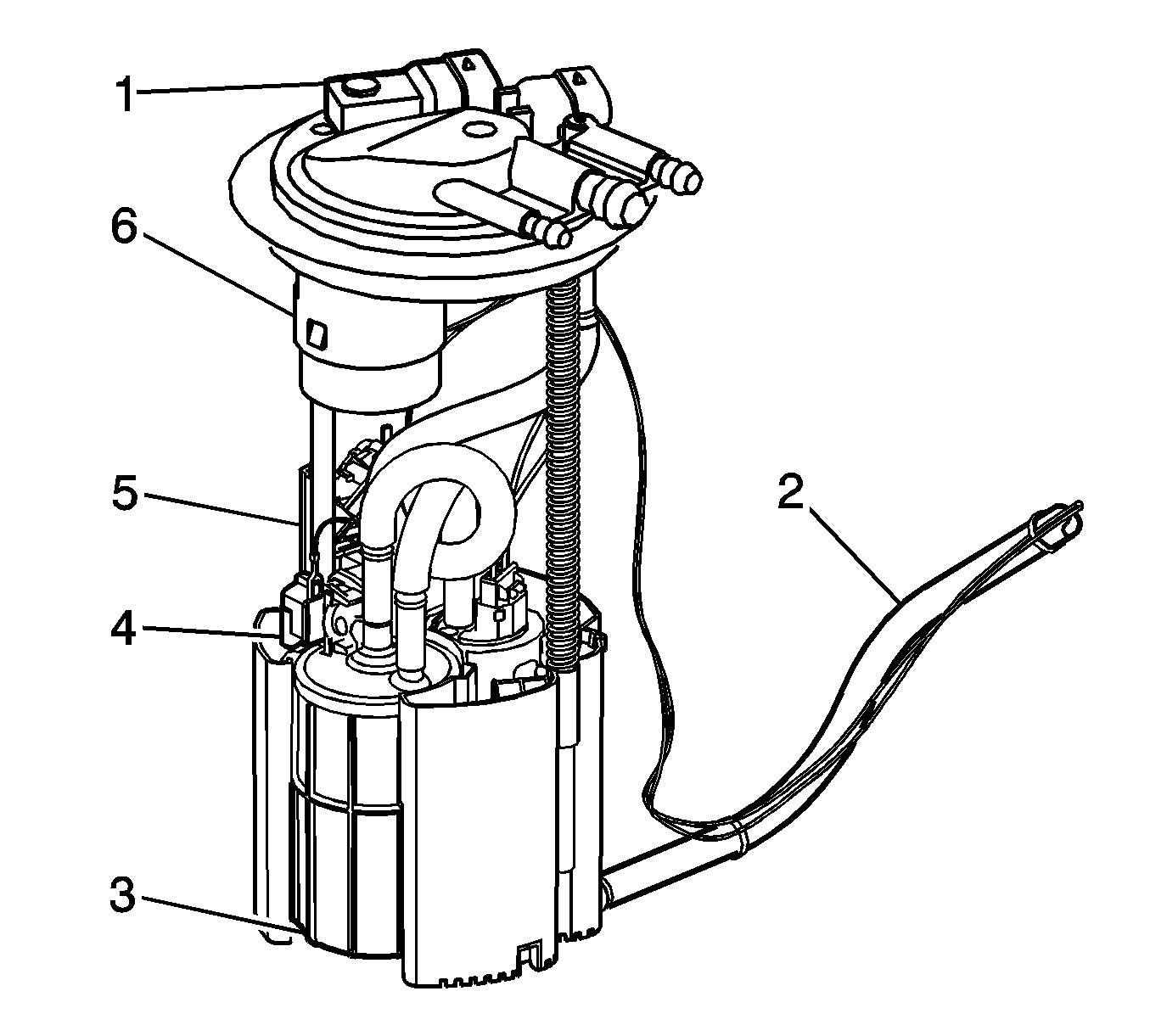
Primary Fuel Tank Module


Object Number: 1335220  Size: SH

The primary fuel tank module is located inside of the right side of the fuel tank. The primary fuel tank module consists of the following major components:

    • The fuel level sensor (4)
    • The fuel pump and reservoir assembly
    • The fuel strainer
    • The primary jet pump
    • The secondary jet pump
    • The fill limiter vent valve (6)
    • The fuel pressure sensor (1)
    • The fuel filter (3)
    • The fuel pressure regulator (5)
    • The fuel transfer pipe (2)

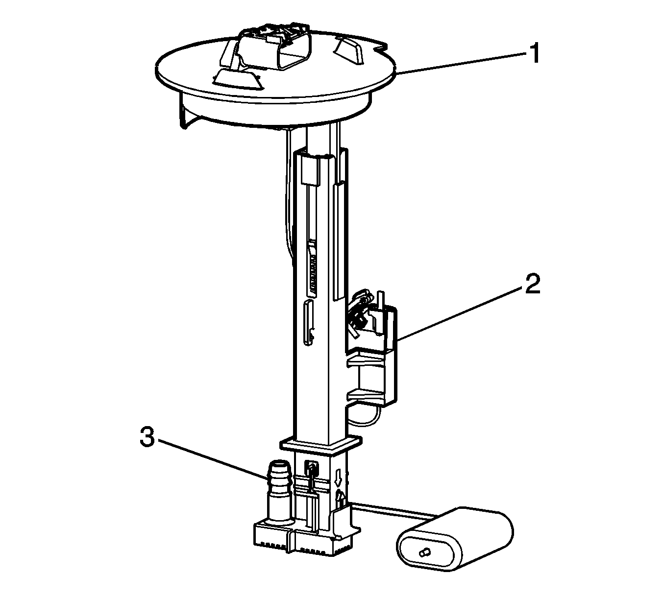
Secondary Fuel Tank Module


Object Number: 1335225  Size: SH

The secondary fuel tank module is located inside of the left side of the fuel tank. The secondary fuel tank module consists of the following major components:

    • The fuel level sensor (1)
    • The fuel pick-up (2)

Fuel Level Sensor

The fuel level sensor consists of a float, a wire float arm, and a ceramic resistor card. The position of the float arm indicates the fuel level. The fuel level sensor contains a variable resistor which changes resistance in correspondence with the position of the float arm. The control module sends the fuel level information via the CAN serial data to the body control module (BCM). The instrument panel cluster (IPC) displays the fuel level as determined by the BCM. This information is used for the IPC fuel gage and the low fuel warning indicator, if applicable. The control module also monitors the fuel level input for various diagnostics.

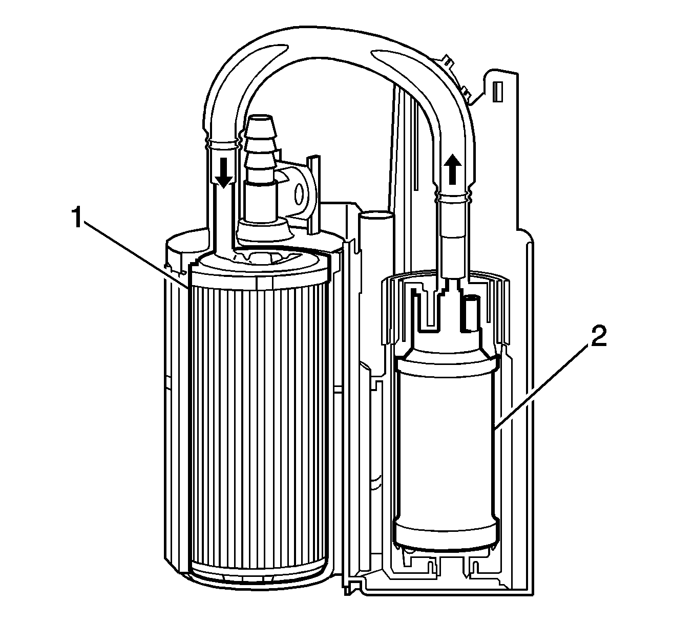
Fuel Pump


Object Number: 1335226  Size: SH

The fuel pump (2) is mounted in the primary fuel tank module reservoir. The fuel pump is an electric high-pressure pump. Fuel is pumped to the fuel injection system at a specified flow and pressure. The fuel pump delivers a constant flow of fuel to the engine even during low fuel conditions and aggressive vehicle maneuvers. The control module controls the electric fuel pump operation through a fuel pump relay.

Primary and Secondary Jet Pumps


Object Number: 1335230  Size: SH

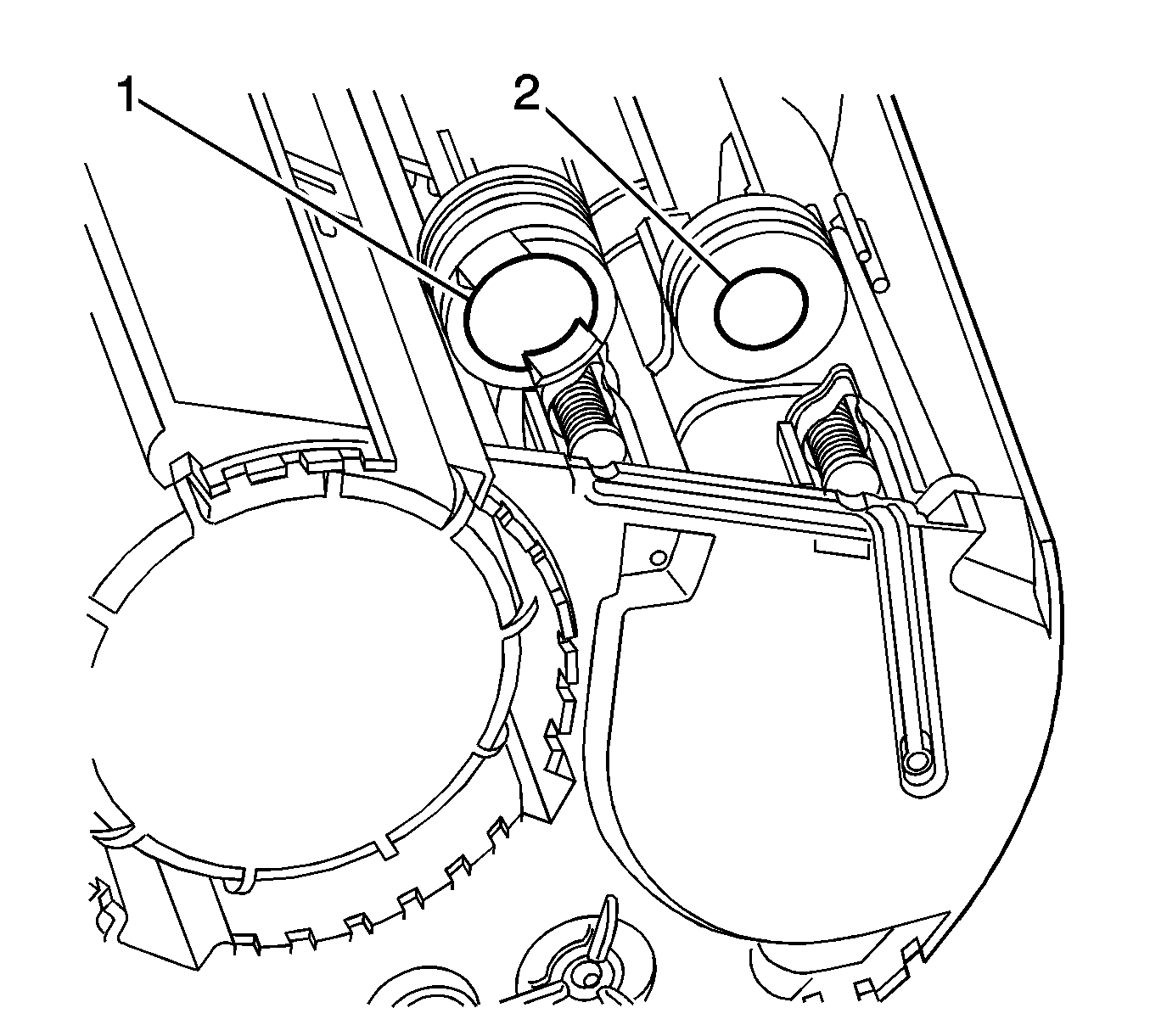
The primary jet pump (1) is located in the primary fuel tank module. Fuel pump flow loss, caused by vapor expulsion in the pump inlet chamber, is diverted to the primary jet pump and the secondary jet pump (2) through a restrictive orifice located on the pump cover. The primary jet pump fills the reservoir of the primary fuel tank module.


Object Number: 1335234  Size: SH

The secondary jet pump (1) creates a venturi action which causes the fuel to be drawn from the secondary side of the fuel tank, through the transfer pipe, to the primary side of the fuel tank.

Fuel Strainer

The fuel strainer attaches to the lower end of the primary fuel tank module. The fuel strainer is made of woven plastic. The functions of the fuel strainer are to filter contaminants and to wick fuel. The fuel strainer normally requires no maintenance. Fuel stoppage at this point indicates that the fuel tank contains an abnormal amount of sediment or contamination.

Fuel Filter


Object Number: 1335226  Size: SH

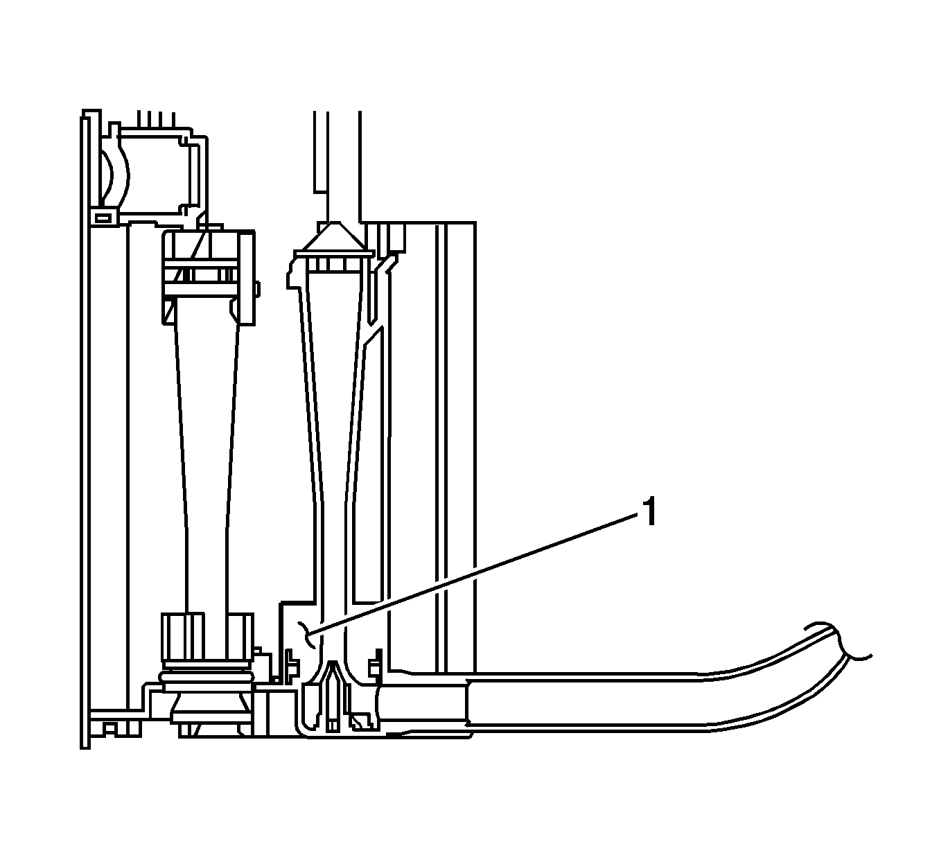
The fuel filter (1) is located in the primary fuel tank module. The paper filter element traps particles in the fuel that may damage the fuel injection system. The filter housing is made to withstand maximum fuel system pressure, exposure to fuel additives, and changes in temperature.

Fuel Pressure Regulator

The fuel pressure regulator is integrated into the fuel filter cover on the primary fuel tank module. The fuel pressure regulator uses a spring with a preset tension and a stainless steel ball inserted into a precision ground seat in order to regulate fuel pressure. This type of fuel pressure regulator is not serviceable.

Fuel Feed Pipes

The fuel feed pipe carries fuel from the fuel tank to the fuel injection system. The fuel pipe consists of 3 sections:

    • The rear fuel pipe is located from the top of the fuel tank to the chassis fuel pipe. The rear fuel pipe is constructed of nylon.
    • The chassis fuel pipe is located under the vehicle and connects the rear fuel pipe to the engine compartment fuel pipe. The chassis fuel pipe is constructed of steel with a section of rubber hose.
    • The engine compartment fuel pipe connects the chassis fuel feed pipe to the fuel rail. The engine compartment fuel pipe is constructed of steel.

Nylon Fuel Pipes

Nylon pipes are constructed to withstand maximum fuel system pressure, exposure to fuel additives, and changes in temperature. The following 2 sizes of nylon pipes are used:

    • 9.53 mm (3/8 in) ID for the fuel feed
    • 12.7 mm (1/2 in) ID for the vent

Heat resistant rubber hose or corrugated plastic conduit protect the sections of the pipes that are exposed to chafing, high temperature, or vibration.

Nylon fuel pipes are somewhat flexible and can be formed around gradual turns under the vehicle. However, if nylon fuel pipes are forced into sharp bends, the pipes kink and restrict the fuel flow. Also, once exposed to fuel, nylon pipes may become stiffer and are more likely to kink if bent too far. Take special care when working on a vehicle with nylon fuel pipes.

Quick-Connect Fittings

Quick-connect fittings provide a simplified means of installing and connecting fuel system components. The fittings consist of a unique female connector and a compatible male pipe end. O-rings, located inside the female connector, provide the fuel seal. Integral locking tabs inside the female connector hold the fittings together.

Fuel Pipe O-rings

O-rings seal the threaded connections in the fuel system. The fuel system O-ring seals are made of special material. Service the O-ring seals with the correct service part.

On-Board Refueling Vapor Recovery System (ORVR)


Object Number: 161608  Size: SH

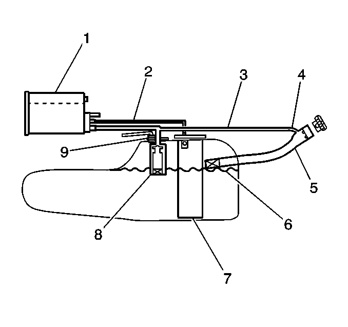
The on-board refueling vapor recovery (ORVR) system is an on-board vehicle system designed to recover fuel vapors during the vehicle refueling operation. Instead of allowing fuel vapors to escape to the atmosphere the ORVR system transports the vapor to the EVAP canister for use by the engine. The flow of liquid fuel down the fuel filler neck provides a liquid seal that prevents fuel vapor from leaving the fuel system. The ORVR system architecture varies from platform to platform. Some of the items listed below are optional depending on the platform application. The following is a list of all the ORVR system components with a brief description of their operation:

    • The EVAP canister (1). The EVAP canister receives and stores refueling vapor from the fuel system. The EVAP canister releases the fuel vapor to the engine through the EVAP control system.
    • The vapor lines (2). The vapor lines transport fuel vapor from the fuel tank assembly to the EVAP canister.
    • The vapor recirculation line (3), if equipped. The vapor recirculation line transports fuel vapor from the fuel tank to the top of the fuel filler pipe during refueling in order to reduce the fuel vapor at the canister. The vapor recirculation line can be located inside the fuel filler pipe or outside of the fuel filler pipe.
    • The variable orifice valve (4), if equipped. The variable orifice valve regulates the amount of vapor allowed to enter the vapor recirculation line.
    • The fuel filler pipe (5). The fuel filler pipe carries fuel from the fuel dispensing nozzle to the fuel tank.
    • The check valve (6). The check valve limits fuel spitback from the fuel tank during the refueling operation by allowing fuel flow only into the fuel tank. The check valve is located at the bottom of the fuel filler pipe or in the fuel tank filler neck.
    • The fuel sender assembly (7). The fuel sender assembly pumps fuel to the engine from the fuel tank.
    • The fill limiter vent valve (8). The fill limiter vent valve is located in the fuel tank and acts as a shut-off valve. The fill limiter vent valve performs the following functions:
       - Controls the fuel tank fill level by closing the primary vent of the fuel tank.
       - Prevents liquid fuel from exiting the fuel tank through the vapor line and entering the EVAP canister.
       - Provides fuel-spillage protection in the event of a vehicle rollover by closing the vapor path from the tank to the EVAP canister.
    • The pressure/vacuum relief valve (9), if equipped. The pressure/vacuum relief valve provides venting of excessive fuel tank pressure or vacuum. The pressure/vacuum relief valve is located in the fuel filler neck on a plastic fuel tank and in the fill limiter vent valve on a steel fuel tank.

Fuel Metering System

The function of the fuel metering system is deliver the correct amount of fuel to the engine under all operating conditions. Fuel is delivered to each cylinder by the fuel injectors. The fuel injectors are controlled sequentially by the powertrain control module (PCM). The PCM bases the control of the fuel injectors on several important engine parameters. These engine parameters include the following:

    • Engine speed (RPM)
    • Accelerator pedal position (APP)
    • Engine coolant temperature (ECT)
    • Intake air temperature (IAT)
    • Manifold absolute pressure (MAP)
    • Fuel control oxygen sensor input (HO2S 1)

Fuel Rail


Object Number: 1257869  Size: SF
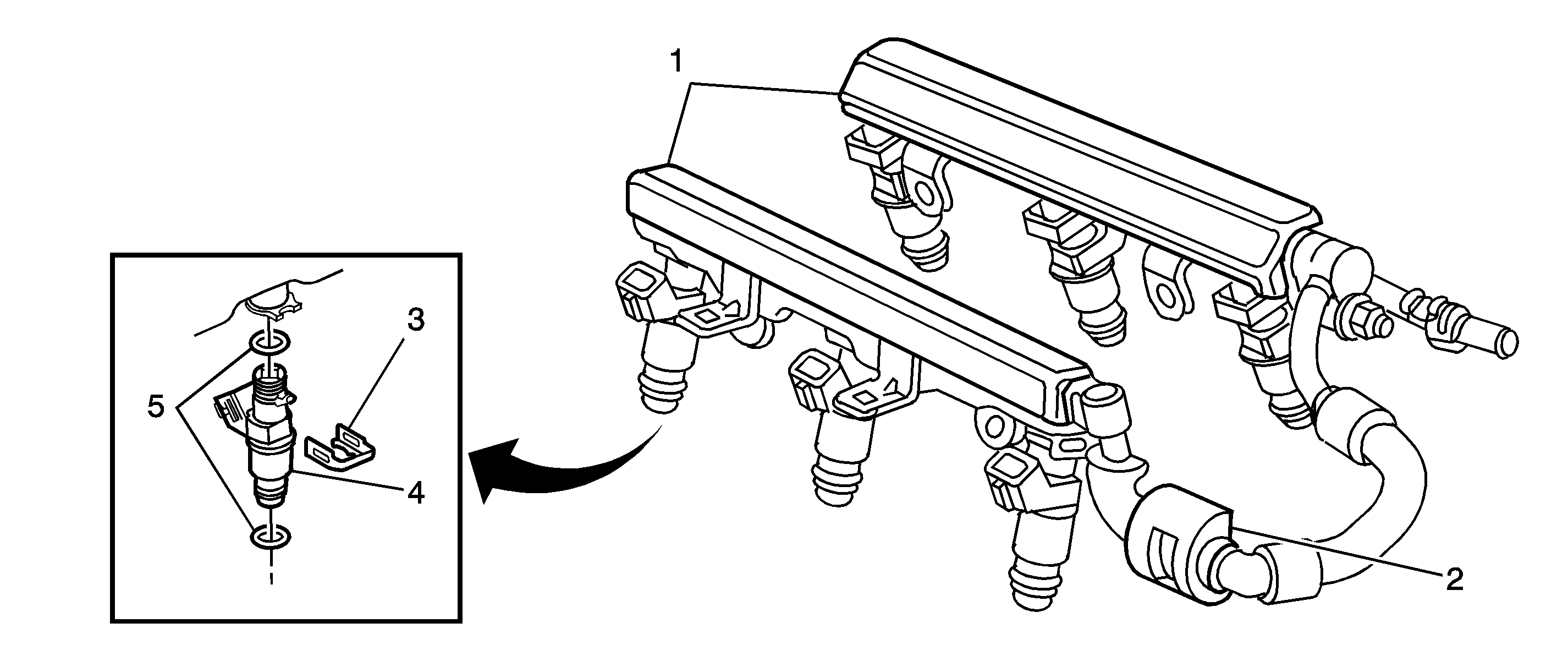
(1)Fuel Rails
(2)Quick Connect Coupling
(3)Retaining Clip
(4)Fuel Injector
(5)O-rings

The fuel rail is mounted on the intake manifold and distributes the fuel to each cylinder through the individual injectors. The fuel is delivered from the pump through the fuel supply line to the inlet pipe of the fuel rail. The fuel inlet pipe directs fuel to both the front and the rear fuel rails (1) suppling the individual fuel injector (4).
Fuel Injectors


Object Number: 1305339  Size: SH
(1)Upper O-ring Seal
(2)Inlet Fuel Filter Screen
(3)Injector Housing
(4)Plunger Spring
(5)Lower O-ring Seal
(6)Needle Valve
(7)Coil

The fuel injector is an electromagnetic (solenoid) type injection nozzle which injects fuel into the intake port of the cylinder head according to the signals from the powertrain control module (PCM). There are 6 fuel injectors, one for each cylinder, located between the intake manifold and the fuel rail.

The PCM energizes the solenoid coil of the fuel injector, generating an electromagnet field that attracts the solenoid plunger. The needle valve, which is incorporated with the solenoid plunger, is opened by the movement of the solenoid plunger. The opening of the needle valve allows fuel that is under pressure to disperse into a cone shaped pattern. Because the stroke of the needle valve in the fuel injector is set constant, the amount of fuel injected at one time is determined by the pulse width injection time--the length of time the solenoid coil is energized.

The fuel injectors may cause various driveability concerns if the following conditions occur:

    • If the injectors will not open
    • If the injectors are stuck open
    • If the injectors are leaking
    • If the injectors have a low or high coil resistance

Engine Fueling

The engine is fueled by 6 individual fuel injectors, one for each cylinder, that are controlled by the PCM. Each fuel injector is fired individually in the engine firing order, which is called a sequential multiport fuel injection. The PCM controls each fuel injector by energizing the fuel injector coil for a brief period once every other engine revolution. The length of this brief period, or pulse, is carefully calculated by the control module in order to deliver the correct amount of fuel for proper driveability and emissions control. The period of time when the fuel injector is energized is called the pulse width and is measured in milliseconds, thousandths of a second.

While the engine is running, the PCM is constantly monitoring the inputs and recalculating the appropriate pulse width for each fuel injector. The pulse width calculation is based on the fuel injector flow rate, mass of fuel the energized fuel injector will pass per unit of time, the desired air/fuel ratio, and actual air mass in each cylinder and is adjusted for battery voltage, short term, and long term fuel trim. The calculated pulse is timed to occur as each cylinders intake valves are closing to attain largest duration and most vaporization.

Fueling during an engine crank is slightly different than fueling during an engine run. As the engine begins to turn, a prime pulse may be injected to speed starting. As soon as the PCM can determine where in the firing order the engine is, the PCM begins pulsing the fuel injectors. The pulse width during the crank is based on the coolant temperature and the engine load.

The fueling system has several automatic adjustments in order to compensate for the differences in the fuel system hardware, the driving conditions, the fuel used, and the vehicle aging. The basis for the fuel control is the pulse width calculation that is described above. Included in this calculation are an adjustment for the battery voltage, the short term fuel trim, and the long term fuel trim. The battery voltage adjustment is necessary since the changes in the voltage across the fuel injector affect the fuel injector flow rate. The short term and the long term fuel trims are fine and gross adjustments to the pulse width that are designed in order to maximize the driveability and emissions control. These fuel trims are based on the feedback from the oxygen sensors in the exhaust stream and are only used when the fuel control system is in a Closed Loop operation.

Fuel Trim Operation

Fuel System Operation

Short Term Fuel Trim Indication

Long Term Fuel Trim Action

Short Term Fuel Trim Response

Lean Condition

1% or More

Increase (1% or more)

Return to 0%

Desired Condition

0%

0%

0%

Rich Condition

-1% or Less

Decrease (-1% or less)

Return to 0%

Air/Fuel Ratio Feedback Compensation - Closed Loop Operation

The wide band heated oxygen sensor (HO2S) measures the amount of oxygen in the exhaust system and provides more information than the switching style HO2S. The wide band sensor consists of an oxygen sensing cell, an oxygen pumping cell, and a heater. The exhaust gas sample passes through a diffusion gap between the sensing cell and the pumping cell. The engine control module (ECM) supplies a voltage to the HO2S and uses this voltage as a reference to the amount of oxygen in the exhaust system. An electronic circuit within the ECM controls the pump current through the oxygen pumping cell in order to maintain a constant voltage in the oxygen sensing cell. The ECM monitors the voltage variation in the sensing cell and attempts to keep the voltage constant by increasing or decreasing the amount of current flow to the pumping cell. By measuring the amount of current required to maintain the voltage in the sensing cell, the ECM can determine the concentration of oxygen in the exhaust. The HO2S voltage is displayed as a lambda value. A lambda value of 1 is equal to a stoichiometric air fuel ratio of 14.7:1. Under normal operating conditions, the lambda value will remain around 1. When the system is lean, the oxygen level will be high and the lambda signal will be high or more than 1. When the oxygen level is low, the lambda signal will be low or less than 1. The ECM uses this information to maintain the proper air/fuel ratio.

In order to obtain efficient performance of the 3-way catalytic converter (TWC) and a high clarification rate of CO, HC and NOx in the exhaust gas stream, the air/fuel mixture must be kept as close to the theoretical air/fuel ratio of 14.7:1 as possible. In order to accomplish this the PCM first compares the actual lambda value of the heated oxygen sensor 1 (HO2S 1) with the reference value of 1. If the HO2S 1 lambda value is less than the 1, the PCM determines that the air/fuel ratio is richer than the theoretical air/fuel ratio and reduces the fuel. If the lambda value of the HO2S 1 is more than 1, the PCM determines that the air/fuel ratio is lean and increases the fuel. By repeating these operations, the PCM can adjust the air/fuel ratio in order to be closer to the theoretical air/fuel ratio. Control of the fuel delivery system as just described is known as CLOSED LOOP operation.

Closed Loop Fuel Control Operation

Air/Fuel Mixture

Exhaust O2 Content

HO2S 1 Output

Fuel System Response

Lean Mixture

High Oxygen

More than One

Rich Command

Rich Mixture

Low Oxygen

Less than One

Lean Command

The Closed Loop fuel control operation will not take place under any of the following conditions:

    • At engine start up
    • When the fuel injection is increased just after engine start up.
    • When the engine coolant temperature (ECT) sensor is indicating a low coolant temperature.
    • When the engine is operating under a high demand, such as at wide open throttle (WOT).
    • During fuel cutoff
    • When the HO2S 1 is cold--Open Loop operation.

Control of the air supply that is mixed with the metered fuel is detailed in the description of the air intake system. Refer to Air Intake System Description .

Synchronous Injection

There are two types of injection timing. One is synchronous injection, when fuel injection is synchronous with the ignition signal or the signal from the camshaft position (CMP) sensor. The other is asynchronous injection, when fuel injection takes place independently of the ignition signal or the signal from the CMP sensor.

When starting the engine, the fuel injectors inject the fuel simultaneously and synchronously at every camshaft position (CMP) sensor signal. When the engine is starting at a cold state, the amount of fuel is determined by the engine coolant temperature (ECT) sensor and is divided and injected.

Once the engine is running, the fuel injection occurs in a cylinder only when the cylinder is in the exhaust stroke. The PCM detects the compression stroke of cylinder 1 through the CMP sensor signal.

Asynchronous Injection

Whenever a change in the throttle valve opening exceeds a specified value, as determined by the PCM, additional fuel is injected simultaneously into the cylinders which are in the intake and exhaust strokes. This is in addition to the above synchronous injection and is not based on the ignition signal.

Engine Starting Enrichment

In order to improve starting performance, fuel enrichment during start up is carried out. For a certain time after the engine is started, the air/fuel mixture is enriched slightly in order to stabilize the engine speed. The amount of compensation varies depending on the engine coolant temperature as measured by the ECT sensor.

Engine Warm-Up Enrichment

When the engine is cold, additional fuel is added in order to ensure good driveability. The level of initial enrichment is determined by the engine coolant temperature (ECT) sensor and intake air temperature (IAT) sensor input. The air/fuel mixture enrichment is gradually decreased until the ECT sensor reaches a specified value.

Acceleration Enrichment

During acceleration, the pulse width of the fuel injectors is lengthened in order to deliver more fuel. The additional fuel that is required is relative to throttle position (TP) sensor and manifold absolute pressure (MAP) sensor input. Acceleration Enrichment ensures smooth and reliable engine acceleration.

High Engine Load Enrichment

In order to provide maximum power during high engine load driving conditions, the air/fuel mixture is enriched when the MAP senor input within a specified PCM calibrated value.

System Voltage Compensation

A power supply system voltage drop will delay the mechanical operation of the fuel injector. The actual injector ON time becomes shorter when the system voltage decreases. In order to compensate for this, the fuel injector pulse width signal is lengthened.

Base Air/Fuel Ratio Compensation

The base air/fuel ratio may vary due to differences in individual engines and mileage. In order to compensate for such variations, feedback information is used to adjust the base air/fuel mixture to maintain the optimum air/fuel ratio.

Fuel Cutoff

Fuel cutoff occurs when the PCM stops fuel injection or turns off the fuel pump. Fuel cutoff is used during the following conditions:

    • During deceleration, when the throttle valve is closed and engine speed is high, fuel injection is stopped so that unburned gas will not be exhausted. Fuel injection starts again when the above conditions are no longer present.
    • When engine speed exceeds 5,000 RPM with no load.
    • When a throttle actuator control (TAC) system malfunction is detected, the engine speed is limited to a maximum of 2,600 RPM.
    • When a accelerator pedal position (APP) malfunction is detected, the engine speed is limited to a maximum of 3,200 RPM.
    • In order to minimize any possible fuel spillage during an airbag deployment event, the fuel pump is de-energized,. The PCM receives a signal from the supplemental inflatable restraint (SIR) system and turns off the fuel pump relay. The relay is re-energized once the ignition switch is cycled off and then on again.